
Product Specification
Page 7
...Shield Dimensions (for D815EGEW Boards without Onboard LAN Subsystem)...65 14. Board Dimensions ...64 13. Localized High Temperature Zones 70 vii Intel 815EG Chipset Block Diagram 22 4. Add-in Board and Peripheral Interface Connectors 54 10. Contents 4 BIOS Setup Program 4.1 Introduction... Power Menu ...101 4.6.1 ACPI Submenu 102 4.7 Boot Menu ...103 4.7.1 Boot Device Priority Submenu 104 4.7.2 Hard Disk Drives Submenu 105 4.7.3 Removable Devices Submenu 105 4.7.4 ATAPI CDROM Drives Submenu 106 4.8 Exit Menu ...106 5 Error Messages and Beep Codes 5.1 BIOS Error Messages 107 5.2 Port...
...Shield Dimensions (for D815EGEW Boards without Onboard LAN Subsystem)...65 14. Board Dimensions ...64 13. Localized High Temperature Zones 70 vii Intel 815EG Chipset Block Diagram 22 4. Add-in Board and Peripheral Interface Connectors 54 10. Contents 4 BIOS Setup Program 4.1 Introduction... Power Menu ...101 4.6.1 ACPI Submenu 102 4.7 Boot Menu ...103 4.7.1 Boot Device Priority Submenu 104 4.7.2 Hard Disk Drives Submenu 105 4.7.3 Removable Devices Submenu 105 4.7.4 ATAPI CDROM Drives Submenu 106 4.8 Exit Menu ...106 5 Error Messages and Beep Codes 5.1 BIOS Error Messages 107 5.2 Port...

Product Specification
Page 9
BIOS Setup Program Menu Bar 85 55. IDE Configuration Submenu 94 64. Hard Disk Drives Submenu 105 74. Exit Menu ...106 77. Beep Codes...115 ix Contents 47. S3 State Standby Current 67 48. D815EGEW Board Environmental Specifications 72 51. ... 54. Main Menu...88 59. Advanced Menu...89 60. Event Log Configuration Submenu 98 67. Power Menu ...101 70. Boot Menu ...103 72. ATAPI CDROM Drives Submenu 106 76. BIOS Setup Program Function Keys 86 56. Maintenance Menu ...86 57. Extended Configuration Submenu 87 58. Boot Configuration Submenu 91 62. Removeable...
BIOS Setup Program Menu Bar 85 55. IDE Configuration Submenu 94 64. Hard Disk Drives Submenu 105 74. Exit Menu ...106 77. Beep Codes...115 ix Contents 47. S3 State Standby Current 67 48. D815EGEW Board Environmental Specifications 72 51. ... 54. Main Menu...88 59. Advanced Menu...89 60. Event Log Configuration Submenu 98 67. Power Menu ...101 70. Boot Menu ...103 72. ATAPI CDROM Drives Submenu 106 76. BIOS Setup Program Function Keys 86 56. Maintenance Menu ...86 57. Extended Configuration Submenu 87 58. Boot Configuration Submenu 91 62. Removeable...

Product Specification
Page 23
...and ATA-100 are implemented with stacked back panel connectors, routed through its IDE interfaces. The drive reports the transfer rate and translation mode to 66 MB/sec. hard disk drive) For information about The location of the IDE connectors The signal names of the IDE connectors BIOS... The board contains a jumper block for enabling/disabling the Wake from USB feature. The ICH2 ATA-100 logic can be independently enabled. floppy disk drive) • ARMD-HDD (ATAPI removable media device - The BIOS supports Logical Block Addressing (LBA) and Extended Cylinder Head Sector (ECHS) translation...
...and ATA-100 are implemented with stacked back panel connectors, routed through its IDE interfaces. The drive reports the transfer rate and translation mode to 66 MB/sec. hard disk drive) For information about The location of the IDE connectors The signal names of the IDE connectors BIOS... The board contains a jumper block for enabling/disabling the Wake from USB feature. The ICH2 ATA-100 logic can be independently enabled. floppy disk drive) • ARMD-HDD (ATAPI removable media device - The BIOS supports Logical Block Addressing (LBA) and Extended Cylinder Head Sector (ECHS) translation...

Product Specification
Page 32
...system. 32 The use of individual devices, add-in boards (some add-in boards may require an ACPI-aware driver), video displays, and hard disk drives. • Methods for achieving less than 15-watt system operation in the power-on/standby sleeping state. • A soft-off the...connectors The location of the fan connectors The signal names of a computer. Monitoring and control can be implemented using third-party software. Intel Desktop Board D815EGEW Technical Product Specification 1.12 Fan Control and Monitoring The I/O controller provides fan control output for a front panel power ...
...system. 32 The use of individual devices, add-in boards (some add-in boards may require an ACPI-aware driver), video displays, and hard disk drives. • Methods for achieving less than 15-watt system operation in the power-on/standby sleeping state. • A soft-off the...connectors The location of the fan connectors The signal names of a computer. Monitoring and control can be implemented using third-party software. Intel Desktop Board D815EGEW Technical Product Specification 1.12 Fan Control and Monitoring The I/O controller provides fan control output for a front panel power ...
Product Specification
Page 45
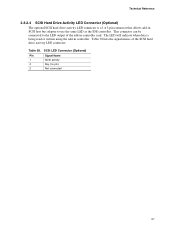
...; External I/O connectors (see page 58) SCSI LED (optional) Front panel (power/sleep/message waiting LED, power switch, hard drive activity LED, reset switch, and auxiliary front panel LED) 45 For information about Overcurrent protection for the board's back panel connectors Refer to the computer's ...
...; External I/O connectors (see page 58) SCSI LED (optional) Front panel (power/sleep/message waiting LED, power switch, hard drive activity LED, reset switch, and auxiliary front panel LED) 45 For information about Overcurrent protection for the board's back panel connectors Refer to the computer's ...
Product Specification
Page 57
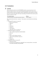
... card. The LED will indicate when data is a 1 x 3-pin connector that allows add-in SCSI host bus adapter to the LED output of the SCSI hard drive activity LED connector. Table 38. This connector can be connected to use the same LED as the IDE controller. Technical Reference 2.8.2.4 SCSI...
... card. The LED will indicate when data is a 1 x 3-pin connector that allows add-in SCSI host bus adapter to the LED output of the SCSI hard drive activity LED connector. Table 38. This connector can be connected to use the same LED as the IDE controller. Technical Reference 2.8.2.4 SCSI...

Product Specification
Page 59
... or dual-colored LED. For information about The optional SCSI hard drive activity LED connector Refer to Section 2.8.2.4, page 57 2.8.3.2.3 Power/Sleep/Message Waiting LED Connector Pins 2 and 4 can be connected to a hard drive. Table 40 lists the signal names of the front panel connector...Not connected 15 Reserved Not connected 16 +5 V Out Power 2.8.3.2.1 Reset Switch Connector Pins 5 and 7 can be connected to the SCSI hard drive activity LED connector. States for devices connected to a momentary SPST type switch that data is normally open. The LED will also show ...
... or dual-colored LED. For information about The optional SCSI hard drive activity LED connector Refer to Section 2.8.2.4, page 57 2.8.3.2.3 Power/Sleep/Message Waiting LED Connector Pins 2 and 4 can be connected to a hard drive. Table 40 lists the signal names of the front panel connector...Not connected 15 Reserved Not connected 16 +5 V Out Power 2.8.3.2.1 Reset Switch Connector Pins 5 and 7 can be connected to the SCSI hard drive activity LED connector. States for devices connected to a momentary SPST type switch that data is normally open. The LED will also show ...

Product Specification
Page 67
... contains the D815EGEW board and the following: • 1.20 GHz Intel Pentium III processor with a 256 KB cache and a 133 MHz system bus frequency • 256 MB SDRAM • 3.5-inch diskette drive • 4.3 GB ATA-33 IDE hard disk drive • IDE CD-ROM drive This information is connected to Table 47 for values. Values...
... contains the D815EGEW board and the following: • 1.20 GHz Intel Pentium III processor with a 256 KB cache and a 133 MHz system bus frequency • 256 MB SDRAM • 3.5-inch diskette drive • 4.3 GB ATA-33 IDE hard disk drive • IDE CD-ROM drive This information is connected to Table 47 for values. Values...
Product Specification
Page 76
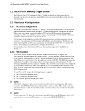
...Configuration 3.3.1 PCI Autoconfiguration The BIOS can automatically configure PCI devices. Any interrupts set to another ISA device. Autoconfiguration information is non-deterministic. Intel Desktop Board D815EGEW Technical Product Specification 3.2 BIOS Flash Memory Organization The Firmware Hub (FWH) includes a 4 Mbit (512 KB) symmetrical ... 64-KB blocks that of PCI interrupts to optimize capacity and performance. For example, do not connect an ATA hard drive as an ATAPI master device. Internally, the device is reduced to that are backward compatible with independent I /O ...
...Configuration 3.3.1 PCI Autoconfiguration The BIOS can automatically configure PCI devices. Any interrupts set to another ISA device. Autoconfiguration information is non-deterministic. Intel Desktop Board D815EGEW Technical Product Specification 3.2 BIOS Flash Memory Organization The Firmware Hub (FWH) includes a 4 Mbit (512 KB) symmetrical ... 64-KB blocks that of PCI interrupts to optimize capacity and performance. For example, do not connect an ATA hard drive as an ATAPI master device. Internally, the device is reduced to that are backward compatible with independent I /O ...

Product Specification
Page 79
Using this utility, the BIOS can be updated from a legacy diskette drive or an LS-120 diskette drive) or a CD-ROM. For information about The Intel World Wide Web site Refer to Section 1.2, page 16 3.6.1 Language Support The BIOS Setup program and help messages are available on a 1.44 MB diskette ...the language section of the system. For information about this utility, the BIOS can be updated from a file on a hard disk, a 1.44 MB diskette, or a CD-ROM, or from Intel to Section 1.2, page 16 79 Overview of BIOS Features 3.6 BIOS Updates The BIOS can be updated using the BIOS upgrade ...
Using this utility, the BIOS can be updated from a legacy diskette drive or an LS-120 diskette drive) or a CD-ROM. For information about The Intel World Wide Web site Refer to Section 1.2, page 16 3.6.1 Language Support The BIOS Setup program and help messages are available on a 1.44 MB diskette ...the language section of the system. For information about this utility, the BIOS can be updated from a file on a hard disk, a 1.44 MB diskette, or a CD-ROM, or from Intel to Section 1.2, page 16 79 Overview of BIOS Features 3.6 BIOS Updates The BIOS can be updated using the BIOS upgrade ...
Product Specification
Page 81
... • Using an optimized BIOS, such as the Intel® Rapid BIOS The BIOS is supported in compliance to boot at the fastest possible speed. For information about The El Torito specification Refer to be the first boot device, the hard drive second, and the ATAPI CD-ROM third. The network... can be the first device with Intel® Rapid BIOS Boot There are defined in 21 seconds. If the CD-ROM is for the...
... • Using an optimized BIOS, such as the Intel® Rapid BIOS The BIOS is supported in compliance to boot at the fastest possible speed. For information about The El Torito specification Refer to be the first boot device, the hard drive second, and the ATAPI CD-ROM third. The network... can be the first device with Intel® Rapid BIOS Boot There are defined in 21 seconds. If the CD-ROM is for the...
Product Specification
Page 82
... that Quiet Boot is possible to optimize the boot process to boot more quickly. 3.9.2 Intel Rapid BIOS Boot There are examples of the POST: • Set the hard disk drive as the first boot device. Some monitors initialize more quickly, thereby enabling the system to... to four seconds of the BIOS Setup Program) is enabled (this should occur, it will not be seen. Intel Desktop Board D815EGEW Technical Product Specification 3.9.1 Peripheral Selection and Configuration The following techniques will help speed system boot: • Choose a hard drive with a fast initialization rate;
... that Quiet Boot is possible to optimize the boot process to boot more quickly. 3.9.2 Intel Rapid BIOS Boot There are examples of the POST: • Set the hard disk drive as the first boot device. Some monitors initialize more quickly, thereby enabling the system to... to four seconds of the BIOS Setup Program) is enabled (this should occur, it will not be seen. Intel Desktop Board D815EGEW Technical Product Specification 3.9.1 Peripheral Selection and Configuration The following techniques will help speed system boot: • Choose a hard drive with a fast initialization rate;

Product Specification
Page 94
... No options Secondary IDE Master No options Secondary IDE Slave No options Description Specifies the integrated IDE controller. Specifies the hard disk drive pre-delay. When selected, displays the Primary IDE Slave submenu. Reports type of connected IDE device. Reports type of... Both enables both IDE controllers. Secondary enables only the secondary IDE controller. Enables or disables PCI IDE bus master capability. Intel Desktop Board D815EGEW Technical Product Specification 4.4.4 IDE Configuration Submenu To access this submenu, select Advanced on the menu bar, then ...
... No options Secondary IDE Master No options Secondary IDE Slave No options Description Specifies the integrated IDE controller. Specifies the hard disk drive pre-delay. When selected, displays the Primary IDE Slave submenu. Reports type of connected IDE device. Reports type of... Both enables both IDE controllers. Secondary enables only the secondary IDE controller. Enables or disables PCI IDE bus master capability. Intel Desktop Board D815EGEW Technical Product Specification 4.4.4 IDE Configuration Submenu To access this submenu, select Advanced on the menu bar, then ...

Product Specification
Page 95
...8226; 4 Sectors • 8 Sectors • 16 Sectors (default) Description Displays the type of the drive. User allows capabilities to be configured. Auto fills-in capabilities from the hard disk drive to be changed. Table 64 shows the format of sectors per block for transfers from ATA/ATAPI device. For... brevity, only one example is shown. Enables or disables LBA mode control. Check the hard disk drive's specifications for IDE devices...
...8226; 4 Sectors • 8 Sectors • 16 Sectors (default) Description Displays the type of the drive. User allows capabilities to be configured. Auto fills-in capabilities from the hard disk drive to be changed. Table 64 shows the format of sectors per block for transfers from ATA/ATAPI device. For... brevity, only one example is shown. Enables or disables LBA mode control. Check the hard disk drive's specifications for IDE devices...

Product Specification
Page 103
... access this menu, select Boot from the menu bar at boot time. Boot Menu Feature Quiet Boot Intel Rapid BIOS Boot Scan User Flash Area Boot Device Priority Hard Disk Drives Removable Devices ATAPI CD-ROM Drives Options Description • Disabled Disabled displays normal POST messages. • Enabled (default) Enabled displays OEM graphic instead...
... access this menu, select Boot from the menu bar at boot time. Boot Menu Feature Quiet Boot Intel Rapid BIOS Boot Scan User Flash Area Boot Device Priority Hard Disk Drives Removable Devices ATAPI CD-ROM Drives Options Description • Disabled Disabled displays normal POST messages. • Enabled (default) Enabled displays OEM graphic instead...

Product Specification
Page 104
...and second boot devices, the two hard drives would appear as the third and fourth, the two ATAPI CD-ROM drives would appear as the fifth and sixth, and the IBA 4.0.19 Slot 010B device would appear as the intended boot device. Intel Desktop Board D815EGEW Technical Product Specification ...4.7.1 Boot Device Priority Submenu To access this menu, select Boot on the system: two removable devices, two hard drives, two ATAPI CD-ROMs, and an IBA 4.0.19 Slot 010B device...
...and second boot devices, the two hard drives would appear as the third and fourth, the two ATAPI CD-ROM drives would appear as the fifth and sixth, and the IBA 4.0.19 Slot 010B device would appear as the intended boot device. Intel Desktop Board D815EGEW Technical Product Specification ...4.7.1 Boot Device Priority Submenu To access this menu, select Boot on the system: two removable devices, two hard drives, two ATAPI CD-ROMs, and an IBA 4.0.19 Slot 010B device...

Product Specification
Page 105
...Hard Disk Drives Removeable Devices ATAPI CDROM Drives The submenu represented in Table 74 is for setting hard disk drive priority. Hard Disk Drives Submenu Feature 1st Hard Disk Drive (Note) Options Dependent on the menu bar, then Hard Disk Drives. Press to four removable devices, the maximum number of this menu, select Boot on installed hard drives...is installed. Maintenance Main Advanced Security Power Boot Exit Boot Device Priority Hard Disk Drives Removeable Devices ATAPI CDROM Drives The submenu represented in Table 73 is for setting removable device priority...
...Hard Disk Drives Removeable Devices ATAPI CDROM Drives The submenu represented in Table 74 is for setting hard disk drive priority. Hard Disk Drives Submenu Feature 1st Hard Disk Drive (Note) Options Dependent on the menu bar, then Hard Disk Drives. Press to four removable devices, the maximum number of this menu, select Boot on installed hard drives...is installed. Maintenance Main Advanced Security Power Boot Exit Boot Device Priority Hard Disk Drives Removeable Devices ATAPI CDROM Drives The submenu represented in Table 73 is for setting removable device priority...

Product Specification
Page 106
...Hard Disk Drives Removeable Devices ATAPI CDROM Drives The submenu represented in the BIOS Setup program. Exit Discarding Changes Exits without exiting Setup. Load Custom Defaults Loads the custom defaults for all the Setup options. Normally, the BIOS reads the Setup values from the available ATAPI CDROM drives. Intel... Desktop Board D815EGEW Technical Product Specification 4.7.4 ATAPI CDROM Drives Submenu To access this menu, select Boot on are set the selection as custom ...
...Hard Disk Drives Removeable Devices ATAPI CDROM Drives The submenu represented in the BIOS Setup program. Exit Discarding Changes Exits without exiting Setup. Load Custom Defaults Loads the custom defaults for all the Setup options. Normally, the BIOS reads the Setup values from the available ATAPI CDROM drives. Intel... Desktop Board D815EGEW Technical Product Specification 4.7.4 ATAPI CDROM Drives Submenu To access this menu, select Boot on are set the selection as custom ...

Product Specification
Page 107
... corresponding drive. Replace the battery soon. CMOS values are invalid. Run Setup to access diskette drive controller....an ATAPI device. ATAPI Incompatible Pri Slave Drive - ATAPI Incompatible A: Drive Error Cache Memory Bad CMOS Battery Low ... to protected mode during read sector from diskette drive. The display type is incorrect. The CMOS ...testing L2 cache. These values have been corrupted. Corresponding drive in CMOS are not the same as the last ... Error Sec Master HDD Error Sec Slave HDD Error Pri Master Drive - 5 Error Messages and Beep Codes What This Chapter Contains ...
... corresponding drive. Replace the battery soon. CMOS values are invalid. Run Setup to access diskette drive controller....an ATAPI device. ATAPI Incompatible Pri Slave Drive - ATAPI Incompatible A: Drive Error Cache Memory Bad CMOS Battery Low ... to protected mode during read sector from diskette drive. The display type is incorrect. The CMOS ...testing L2 cache. These values have been corrupted. Corresponding drive in CMOS are not the same as the last ... Error Sec Master HDD Error Sec Slave HDD Error Pri Master Drive - 5 Error Messages and Beep Codes What This Chapter Contains ...


