Product Guide
Page 3
Contents 1 Desktop Board Features Manufacturing Options ...11 Components...12 Processors ...14 Main Memory ...15 Chipsets ...16 Intel® 82815E Graphics Memory Controller Hub (GMCH) ...17 Intel® 82815EP Memory Controller Hub (MCH) ...17 Intel® 82801BA I/O Controller Hub (ICH2) ...17 Firmware Hub (FWH) ...18 ... ...20 PCI Auto Configuration ...20 IDE Auto Configuration ...20 Security Passwords ...21 Speaker...21 LAN Subsystem (Optional) ...21 Intel® 82562ET Platform LAN Connect Device ...21 LAN Subsystem Software...22 RJ-45 LAN Connector LEDs...22 Battery...22 Power Management...
Contents 1 Desktop Board Features Manufacturing Options ...11 Components...12 Processors ...14 Main Memory ...15 Chipsets ...16 Intel® 82815E Graphics Memory Controller Hub (GMCH) ...17 Intel® 82815EP Memory Controller Hub (MCH) ...17 Intel® 82801BA I/O Controller Hub (ICH2) ...17 Firmware Hub (FWH) ...18 ... ...20 PCI Auto Configuration ...20 IDE Auto Configuration ...20 Security Passwords ...21 Speaker...21 LAN Subsystem (Optional) ...21 Intel® 82562ET Platform LAN Connect Device ...21 LAN Subsystem Software...22 RJ-45 LAN Connector LEDs...22 Battery...22 Power Management...

Product Guide
Page 4
...the I/O Shield ...33 Installing the Desktop Board...34 Installing a Processor ...36 Removing the Processor ...38 Installing a 1 GHz Processor Fan Heatsink ...39 Removing the 1 GHz Processor Fan Heatsink ...42 Replacing the Battery ...43 Replacing the Battery ...on the D815EEA2 and D815EPEA2 Boards ...45 Replacing the Battery on the D815EFV and D815EPFV Boards ...46 Connecting the IDE Cable ...47 Setting the BIOS Configuration Jumper...48 Clearing the Passwords...49 3 Updating the BIOS Updating the BIOS with the Intel...
...the I/O Shield ...33 Installing the Desktop Board...34 Installing a Processor ...36 Removing the Processor ...38 Installing a 1 GHz Processor Fan Heatsink ...39 Removing the 1 GHz Processor Fan Heatsink ...42 Replacing the Battery ...43 Replacing the Battery ...on the D815EEA2 and D815EPEA2 Boards ...45 Replacing the Battery on the D815EFV and D815EPFV Boards ...46 Connecting the IDE Cable ...47 Setting the BIOS Configuration Jumper...48 Clearing the Passwords...49 3 Updating the BIOS Updating the BIOS with the Intel...
Product Guide
Page 5
...and D815EPEA2 Desktop Board Components...12 D815EFV and D815EPFV Desktop Board Components ...13 Location of Standby Power Indicator (the D815EEA2 Board Is Shown)...24 DIMM Socket Locations (the D815EEA2 Board Is Shown) ...27 Retention Notch Shown on an AGP Card ...28 AGP Connector Location and Retention Mechanism (RM) Placement...Certifications ...94 Prevent Power Supply Overload...94 Place Battery Marking ...94 Use Only for the D815EFV and D815EPFV Boards...35 Installing the Processor in the Processor Socket ...36 Attaching the Heatsink to the Processor ...37 Attaching the Fan Heatsink Clips to the...
...and D815EPEA2 Desktop Board Components...12 D815EFV and D815EPFV Desktop Board Components ...13 Location of Standby Power Indicator (the D815EEA2 Board Is Shown)...24 DIMM Socket Locations (the D815EEA2 Board Is Shown) ...27 Retention Notch Shown on an AGP Card ...28 AGP Connector Location and Retention Mechanism (RM) Placement...Certifications ...94 Prevent Power Supply Overload...94 Place Battery Marking ...94 Use Only for the D815EFV and D815EPFV Boards...35 Installing the Processor in the Processor Socket ...36 Attaching the Heatsink to the Processor ...37 Attaching the Fan Heatsink Clips to the...
Product Guide
Page 6
...on the Fan Heatsink...39 Lowering the Plastic Clip Handle...40 Attaching the Fan to the Fan Heatsink ...41 Connecting the Processor Fan Cable to the Processor Fan Connector ...41 Removing the Fan Heatsink...42 Removing the Battery from the D815EEA2 and D815EPEA2 Boards ...45 Removing the ... Submenus...67 Diskette Configuration Submenu ...68 Event Log Configuration Submenu ...69 Video Configuration Submenu ...70 Security Menu...71 Power Menu...72 APM Submenu...73 vi Intel Desktop Boards D815EEA2, D815EPEA2, D815EFV, and D815EPFV Product Guide 16. 17. 18. 19. 20. 21. 22. 23. 24. 25. 26. 27. ...
...on the Fan Heatsink...39 Lowering the Plastic Clip Handle...40 Attaching the Fan to the Fan Heatsink ...41 Connecting the Processor Fan Cable to the Processor Fan Connector ...41 Removing the Fan Heatsink...42 Removing the Battery from the D815EEA2 and D815EPEA2 Boards ...45 Removing the ... Submenus...67 Diskette Configuration Submenu ...68 Event Log Configuration Submenu ...69 Video Configuration Submenu ...70 Security Menu...71 Power Menu...72 APM Submenu...73 vi Intel Desktop Boards D815EEA2, D815EPEA2, D815EFV, and D815EPFV Product Guide 16. 17. 18. 19. 20. 21. 22. 23. 24. 25. 26. 27. ...

Product Guide
Page 9
...ATX at 11.55 inches by 8.20 inches (D815EEA2 and D815EPEA2) • microATX at 9.6 inches by 8.2 inches (D815EFV and D815EPFV) Processors • Intel® Pentium® III processor family with FC-PGA (Flip Chip Pin Grid Array) package supporting 100 MHz and 133 MHz system bus frequency • Intel® Celeron™ processor... family with FC-PGA package supporting 66 MHz and 100 MHz system bus frequency Memory Three 168-pin Dual Inline Memory Module (DIMM) sockets supporting: • 100 MHz PC100 SDRAM (...
...ATX at 11.55 inches by 8.20 inches (D815EEA2 and D815EPEA2) • microATX at 9.6 inches by 8.2 inches (D815EFV and D815EPFV) Processors • Intel® Pentium® III processor family with FC-PGA (Flip Chip Pin Grid Array) package supporting 100 MHz and 133 MHz system bus frequency • Intel® Celeron™ processor... family with FC-PGA package supporting 66 MHz and 100 MHz system bus frequency Memory Three 168-pin Dual Inline Memory Module (DIMM) sockets supporting: • 100 MHz PC100 SDRAM (...

Product Guide
Page 12
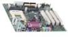
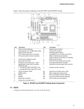
... connector Front panel audio connector (optional) ATAPI-style CD-ROM connector Back panel connectors Processor fan connector (fan 1, tach) Digital Video Output (DVO) connector (D815EEA2 only) • Intel 82815E GMCH (D815EEA2 only) • Intel 82815EP MCH (D815EPEA2 only) 370-pin processor socket DIMM sockets Chassis fan connector (fan 3) Speaker Main power connector Diskette drive connector Q R S T U V W X Y Z AA BB...
... connector Front panel audio connector (optional) ATAPI-style CD-ROM connector Back panel connectors Processor fan connector (fan 1, tach) Digital Video Output (DVO) connector (D815EEA2 only) • Intel 82815E GMCH (D815EEA2 only) • Intel 82815EP MCH (D815EPEA2 only) 370-pin processor socket DIMM sockets Chassis fan connector (fan 3) Speaker Main power connector Diskette drive connector Q R S T U V W X Y Z AA BB...
Product Guide
Page 13
... connector Front panel audio connector (optional) ATAPI-style CD-ROM connector Back panel connectors Processor fan connector (fan 1, tach) Digital Video Output (DVO) connector (D815EFV only) • Intel 82815E GMCH (D815EFV only) • Intel 82815EP MCH (D815EPFV only) 370-pin processor socket DIMM sockets Battery Speaker Main power connector Chassis fan connector (fan 3) Q R S T U V W X Y Z AA BB CC DD...
... connector Front panel audio connector (optional) ATAPI-style CD-ROM connector Back panel connectors Processor fan connector (fan 1, tach) Digital Video Output (DVO) connector (D815EFV only) • Intel 82815E GMCH (D815EFV only) • Intel 82815EP MCH (D815EPFV only) 370-pin processor socket DIMM sockets Battery Speaker Main power connector Chassis fan connector (fan 3) Q R S T U V W X Y Z AA BB CC DD...

Product Guide
Page 14
... latest list of unsupported processors can damage the board, the processor, and the power supply. The processor connects to the Intel desktop board Web site at: http://support.intel.com/support/motherboards/desktop/ For instructions on installing or upgrading the processor, see Chapter 2. 14 Processor Type Intel Pentium III processors Supported Processors Socket Type FC-PGA Processor Frequency (GHz) 1.0 Processor Frequency (MHz) 933, 866...
... latest list of unsupported processors can damage the board, the processor, and the power supply. The processor connects to the Intel desktop board Web site at: http://support.intel.com/support/motherboards/desktop/ For instructions on installing or upgrading the processor, see Chapter 2. 14 Processor Type Intel Pentium III processors Supported Processors Socket Type FC-PGA Processor Frequency (GHz) 1.0 Processor Frequency (MHz) 933, 866...
Product Guide
Page 16
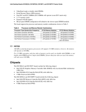
... Memory Modules...will operate at 100 MHz ...will operate at 100 MHz ...will operate at 100 MHz ...will operate at 133 MHz (see note below) Processor Type (System Bus Frequency) Intel Celeron processor (66 MHz) Intel Celeron processor (100 MHz) Intel Pentium III processor (100 MHz) Intel Pentium III processor (133 MHz) ✏ NOTES 100 MHz system bus frequency...
... Memory Modules...will operate at 100 MHz ...will operate at 100 MHz ...will operate at 100 MHz ...will operate at 133 MHz (see note below) Processor Type (System Bus Frequency) Intel Celeron processor (66 MHz) Intel Celeron processor (100 MHz) Intel Pentium III processor (100 MHz) Intel Pentium III processor (133 MHz) ✏ NOTES 100 MHz system bus frequency...
Product Guide
Page 19
Desktop Board Features ✏ NOTE Computer systems that meets the requirements for a full-speed USB device. PCI Enhanced IDE Interface The PCI enhanced IDE interface handles the exchange of information between the processor and peripheral devices like hard disks, CD-ROM drives, and Iomega ZIP Use a shielded cable that have an unshielded cable attached to a USB port might not meet FCC Class B requirements even if no device or a low-speed USB device is attached to the cable.
Desktop Board Features ✏ NOTE Computer systems that meets the requirements for a full-speed USB device. PCI Enhanced IDE Interface The PCI enhanced IDE interface handles the exchange of information between the processor and peripheral devices like hard disks, CD-ROM drives, and Iomega ZIP Use a shielded cable that have an unshielded cable attached to a USB port might not meet FCC Class B requirements even if no device or a low-speed USB device is attached to the cable.
Product Guide
Page 25
... remove the AGP card retention mechanism (included) Install and remove AGP and GPA cards Install the I/O shield Install the desktop board Install and remove the processor Replace the battery Connect the IDE cable Set the BIOS configuration jumper Before You Begin ✏ NOTE Before you install the desktop board in a chassis...
... remove the AGP card retention mechanism (included) Install and remove AGP and GPA cards Install the I/O shield Install the desktop board Install and remove the processor Replace the battery Connect the IDE cable Set the BIOS configuration jumper Before You Begin ✏ NOTE Before you install the desktop board in a chassis...
Product Guide
Page 36
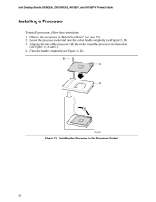
Close the handle completely (see Figure 13, A and C). 4. Installing the Processor in "Before You Begin" (see Figure 13, B). 3. Aligning the pins of the processor with the socket, insert the processor into the socket (see Figure 13, D). Locate the processor socket and raise the socket handle completely (see page 25). 2. Observe the precautions in the Processor Socket 36 B C A D OM11639 Figure 13. Intel Desktop Boards D815EEA2, D815EPEA2, D815EFV, and D815EPFV Product Guide Installing a Processor To install a processor, follow these instructions: 1.
Close the handle completely (see Figure 13, A and C). 4. Installing the Processor in "Before You Begin" (see Figure 13, B). 3. Aligning the pins of the processor with the socket, insert the processor into the socket (see Figure 13, D). Locate the processor socket and raise the socket handle completely (see page 25). 2. Observe the precautions in the Processor Socket 36 B C A D OM11639 Figure 13. Intel Desktop Boards D815EEA2, D815EPEA2, D815EFV, and D815EPFV Product Guide Installing a Processor To install a processor, follow these instructions: 1.

Product Guide
Page 37
Place the fan heatsink on how to the processor socket (see Figure 14). Attaching the Heatsink to the Processor Socket 37 Attach the fan heatsink clips to install a fan heatsink for a processor 1 GHz or greater, see page 39. 5. P G A 37 OM11619 Figure 14. Attaching the Fan Heatsink Clips to the Processor 6. Installing and Replacing Desktop Board Components ✏ NOTE For instructions on top of the processor (see Figure 15). 0 A B OM11620 A B Fan heatsink clip Processor socket Figure 15.
Place the fan heatsink on how to the processor socket (see Figure 14). Attaching the Heatsink to the Processor Socket 37 Attach the fan heatsink clips to install a fan heatsink for a processor 1 GHz or greater, see page 39. 5. P G A 37 OM11619 Figure 14. Attaching the Fan Heatsink Clips to the Processor 6. Installing and Replacing Desktop Board Components ✏ NOTE For instructions on top of the processor (see Figure 15). 0 A B OM11620 A B Fan heatsink clip Processor socket Figure 15.
Product Guide
Page 38
... (see page 25). 2. Remove the heatsink. 5. Connect the processor fan cable to the Processor Fan Connector Removing the Processor To remove the processor, follow these instructions: 1. Observe the precautions in "Before You Begin" (see Figure 16). Detach the fan heatsink clips. 4. Raise the socket handle completely. 6. Intel Desktop Boards D815EEA2, D815EPEA2, D815EFV, and D815EPFV Product Guide 7.
... (see page 25). 2. Remove the heatsink. 5. Connect the processor fan cable to the Processor Fan Connector Removing the Processor To remove the processor, follow these instructions: 1. Observe the precautions in "Before You Begin" (see Figure 16). Detach the fan heatsink clips. 4. Raise the socket handle completely. 6. Intel Desktop Boards D815EEA2, D815EPEA2, D815EFV, and D815EPFV Product Guide 7.

Product Guide
Page 39
Attaching the Fan Heatsink Over the Processor 2. A OM11063 Figure 17. Placing the Plastic Clip on the processor socket label side (see Figure 17, A). B C A OM11064 Figure 18. The inset in the up position, place the plastic clip (see Figure 18, B) on ...page 36, Figure 13. Attach the fan heatsink to install the fan heatsink on a processor 1 GHz or greater. 1. Installing ...
Attaching the Fan Heatsink Over the Processor 2. A OM11063 Figure 17. Placing the Plastic Clip on the processor socket label side (see Figure 17, A). B C A OM11064 Figure 18. The inset in the up position, place the plastic clip (see Figure 18, B) on ...page 36, Figure 13. Attach the fan heatsink to install the fan heatsink on a processor 1 GHz or greater. 1. Installing ...
Product Guide
Page 40
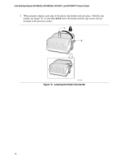
Intel Desktop Boards D815EEA2, D815EPEA2, D815EFV, and D815EPFV Product Guide 3. When properly aligned, each edge of the plastic clip should click into place. Hold the clip handle (see Figure 19, A) and very slowly lower the handle until the clip secures the fan heatsink to the processor socket. Lowering the Plastic Clip Handle 40 A B OM11062 Figure 19.
Intel Desktop Boards D815EEA2, D815EPEA2, D815EFV, and D815EPFV Product Guide 3. When properly aligned, each edge of the plastic clip should click into place. Hold the clip handle (see Figure 19, A) and very slowly lower the handle until the clip secures the fan heatsink to the processor socket. Lowering the Plastic Clip Handle 40 A B OM11062 Figure 19.

Product Guide
Page 41
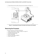
A B C OM11061 Figure 20. Clip the fan (A) over the fan heatsink (B) as illustrated in Figure 20. Attaching the Fan to the Processor Fan Connector 41 Installing and Replacing Desktop Board Components 4. Connecting the Processor Fan Cable to the Fan Heatsink 5. Connect the processor fan cable to the processor fan connector (see Figure 21). J1B1 J1B1 OM11175 Figure 21.
A B C OM11061 Figure 20. Clip the fan (A) over the fan heatsink (B) as illustrated in Figure 20. Attaching the Fan to the Processor Fan Connector 41 Installing and Replacing Desktop Board Components 4. Connecting the Processor Fan Cable to the Fan Heatsink 5. Connect the processor fan cable to the processor fan connector (see Figure 21). J1B1 J1B1 OM11175 Figure 21.
Product Guide
Page 42
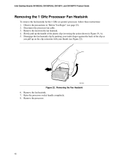
... on the clip extension with your thumb (see page 25). 2. Raise the processor socket handle completely. 8. Intel Desktop Boards D815EEA2, D815EPEA2, D815EFV, and D815EPFV Product Guide Removing the 1 GHz Processor Fan Heatsink To remove the fan heatsink for the 1 GHz (or greater) processor, follow these instructions: 1. Removing the Fan Heatsink 6. Remove the fan from the...
... on the clip extension with your thumb (see page 25). 2. Raise the processor socket handle completely. 8. Intel Desktop Boards D815EEA2, D815EPEA2, D815EFV, and D815EPFV Product Guide Removing the 1 GHz Processor Fan Heatsink To remove the fan heatsink for the 1 GHz (or greater) processor, follow these instructions: 1. Removing the Fan Heatsink 6. Remove the fan from the...

Product Guide
Page 58
Intel Desktop Boards D815EEA2, D815EPEA2, D815EFV, and D815EPFV Product Guide Table 9 shows the function keys available for information about setting the configure mode. Table 9. See page ... BIOS Setup Program Function Key or or Maintenance Menu This menu is used to clear passwords, to access the extended configuration submenu, and to access processor information. Invokes the Extended Configuration submenu. BIOS Setup Program Function Keys Description Selects a different menu screen Moves cursor up or down Moves cursor to the...
Intel Desktop Boards D815EEA2, D815EPEA2, D815EFV, and D815EPFV Product Guide Table 9 shows the function keys available for information about setting the configure mode. Table 9. See page ... BIOS Setup Program Function Key or or Maintenance Menu This menu is used to clear passwords, to access the extended configuration submenu, and to access processor information. Invokes the Extended Configuration submenu. BIOS Setup Program Function Keys Description Selects a different menu screen Moves cursor up or down Moves cursor to the...
Product Guide
Page 59
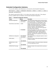
Maintenance Main Advanced Security Power Boot Exit Extended Configuration The submenu represented by the processor. If selected here, will also display in memory. Both the video driver and the application must support Write Combining. Cache lookups are not performed. Selects ...
Maintenance Main Advanced Security Power Boot Exit Extended Configuration The submenu represented by the processor. If selected here, will also display in memory. Both the video driver and the application must support Write Combining. Cache lookups are not performed. Selects ...


