
Technical Product Specification
Page 7
... Support 18 1.3 Processor 18 1.4 System Memory 19 1.4.1 Memory Configurations 20 1.5 Processor Graphics Subsystem 21 1.5.1 Integrated Graphics 21 1.5.2 USB 24 1.6 SATA Interface 25 1.6.1 AHCI Mode 25 1.6.2 Intel® Rapid Storage Technology / SATA RAID 25 1.6.3 Intel® Smart Response Technology 25 1.7 Real-Time Clock Subsystem 26 1.8 Audio Subsystem 26 1.8.1 Audio Subsystem Software 27 1.9 LAN Subsystem 27...
... Support 18 1.3 Processor 18 1.4 System Memory 19 1.4.1 Memory Configurations 20 1.5 Processor Graphics Subsystem 21 1.5.1 Integrated Graphics 21 1.5.2 USB 24 1.6 SATA Interface 25 1.6.1 AHCI Mode 25 1.6.2 Intel® Rapid Storage Technology / SATA RAID 25 1.6.3 Intel® Smart Response Technology 25 1.7 Real-Time Clock Subsystem 26 1.8 Audio Subsystem 26 1.8.1 Audio Subsystem Software 27 1.9 LAN Subsystem 27...

Technical Product Specification
Page 10
...SATA Connector 43 17. Environmental Specifications 56 27. Boot Device Menu Options 61 29. Master Key and User Hard Drive Password Functions 63 30. Supervisor and User Password Functions 64 31. Front-panel Power LED Blink Codes 65 32. EMC Regulations 69 35. Intel NUC Board D54250WYB and Intel... 44 19. 12-24 V Internal Power Supply Connector 45 20. States for Components 55 26. BIOS Security Jumper Settings 50 23. SATA Power Connector 44 18. Front Panel Header (2.0 mm Pitch 45 21. Thermal Considerations for BIOS Recovery 60 28. Acceptable Drives/Media Types...
...SATA Connector 43 17. Environmental Specifications 56 27. Boot Device Menu Options 61 29. Master Key and User Hard Drive Password Functions 63 30. Supervisor and User Password Functions 64 31. Front-panel Power LED Blink Codes 65 32. EMC Regulations 69 35. Intel NUC Board D54250WYB and Intel... 44 19. 12-24 V Internal Power Supply Connector 45 20. States for Components 55 26. BIOS Security Jumper Settings 50 23. SATA Power Connector 44 18. Front Panel Header (2.0 mm Pitch 45 21. Thermal Considerations for BIOS Recovery 60 28. Acceptable Drives/Media Types...
Technical Product Specification
Page 11
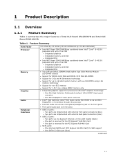
...interfaces through the processor • Intel HD Audio via one dual-port internal 2.0 mm pitch header (black) ― One port is reserved for the PCI Express* Half-Mini Card ― One port is reserved for the PCI Express Full-Mini Card • SATA ports: ― One internal...) for SSD support ― One SATA 6.0 Gb/s port (blue) continued 11 Feature Summary Form Factor Processor Memory Graphics Audio Peripheral Interfaces 4.0 inches by 4.0 inches (101.60 millimeters by 101.60 millimeters) • Intel NUC Board D54250WYB has a soldered-down Intel® Core™ i5-4250U processor...
...interfaces through the processor • Intel HD Audio via one dual-port internal 2.0 mm pitch header (black) ― One port is reserved for the PCI Express* Half-Mini Card ― One port is reserved for the PCI Express Full-Mini Card • SATA ports: ― One internal...) for SSD support ― One SATA 6.0 Gb/s port (blue) continued 11 Feature Summary Form Factor Processor Memory Graphics Audio Peripheral Interfaces 4.0 inches by 4.0 inches (101.60 millimeters by 101.60 millimeters) • Intel NUC Board D54250WYB has a soldered-down Intel® Core™ i5-4250U processor...
Technical Product Specification
Page 25
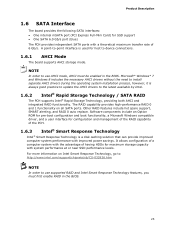
... system performance at or near SSD performance levels. It allows configuration of having HDDs for host to the latest available by Intel. 1.6.2 Intel® Rapid Storage Technology / SATA RAID The PCH supports Intel® Rapid Storage Technology, providing both AHCI and integrated RAID functionality. A point-to-point interface is always good practice to update...
... system performance at or near SSD performance levels. It allows configuration of having HDDs for host to the latest available by Intel. 1.6.2 Intel® Rapid Storage Technology / SATA RAID The PCH supports Intel® Rapid Storage Technology, providing both AHCI and integrated RAID functionality. A point-to-point interface is always good practice to update...

Technical Product Specification
Page 41
Technical Reference Table 13 lists the connectors and headers identified in Figure 10 Item from Figure 10 Description A PCI Express Full-Mini Card connector B PCI Express Half-Mini Card connector C SATA 6.0 Gb/s connector through the PCH D Front panel dual-port USB 2.0 header (2.0 mm pitch) E Front panel header (2.0 mm pitch) F SATA power connector G BIOS setup configuration jumper H Internal DC power connector 41 Table 13. Connectors and Headers Shown in Figure 10.
Technical Reference Table 13 lists the connectors and headers identified in Figure 10 Item from Figure 10 Description A PCI Express Full-Mini Card connector B PCI Express Half-Mini Card connector C SATA 6.0 Gb/s connector through the PCH D Front panel dual-port USB 2.0 header (2.0 mm pitch) E Front panel header (2.0 mm pitch) F SATA power connector G BIOS setup configuration jumper H Internal DC power connector 41 Table 13. Connectors and Headers Shown in Figure 10.

Technical Product Specification
Page 43
... 2.0 Header Pin Signal Name Pin Signal Name 1 +5 V DC 2 +5 V DC 3 D− 4 D− 5 D+ 6 D+ 7 Ground 8 Ground 9 KEY (no pin) 10 No Connect Table 16. Technical Reference Table 14. SATA Connector Pin Signal Name 1 Ground 2 TXP 3 TXN 4 Ground 5 RXN 6 RXP 7 Ground 43
... 2.0 Header Pin Signal Name Pin Signal Name 1 +5 V DC 2 +5 V DC 3 D− 4 D− 5 D+ 6 D+ 7 Ground 8 Ground 9 KEY (no pin) 10 No Connect Table 16. Technical Reference Table 14. SATA Connector Pin Signal Name 1 Ground 2 TXP 3 TXN 4 Ground 5 RXN 6 RXP 7 Ground 43

Technical Product Specification
Page 44
... Connectors The board has the following add-in card connectors: • One PCI Express Half-Mini Card • One PCI Express Full-Mini Card 44 SATA Power Connector Pin Signal Name 1 3.3 V DC 2 3.3 V DC 3 3.3 V DC 4 Ground 5 Ground 6 Ground 7 5 V DC 8 5 V DC 9 5 V DC 10 Ground 11 Ground 12 Ground 13 N/A 14 N/A 15 N/A Table 18...
... Connectors The board has the following add-in card connectors: • One PCI Express Half-Mini Card • One PCI Express Full-Mini Card 44 SATA Power Connector Pin Signal Name 1 3.3 V DC 2 3.3 V DC 3 3.3 V DC 4 Ground 5 Ground 6 Ground 7 5 V DC 8 5 V DC 9 5 V DC 10 Ground 11 Ground 12 Ground 13 N/A 14 N/A 15 N/A Table 18...

Technical Product Specification
Page 46
...Standby Steady Normal operation NOTE The LED behavior shown in Table 21 is default - Proper LED function requires a SATA hard drive or optical drive connected to an onboard SATA connector. 2.2.4.4.2 Reset Switch Header Pins 5 and 7 can be connected to a one- When the switch is... board resets and runs the POST. 2.2.4.4.3 Power/Sleep LED Header Pins 2 and 4 can be set via BIOS setup. 46 Intel NUC Board D54250WYB and Intel NUC Board D34010WYB Technical Product Specification Figure 13. States for Front Panel Header (2.0 mm Pitch) 2.2.4.4.1 Hard Drive Activity LED Header Pins...
...Standby Steady Normal operation NOTE The LED behavior shown in Table 21 is default - Proper LED function requires a SATA hard drive or optical drive connected to an onboard SATA connector. 2.2.4.4.2 Reset Switch Header Pins 5 and 7 can be connected to a one- When the switch is... board resets and runs the POST. 2.2.4.4.3 Power/Sleep LED Header Pins 2 and 4 can be set via BIOS setup. 46 Intel NUC Board D54250WYB and Intel NUC Board D34010WYB Technical Product Specification Figure 13. States for Front Panel Header (2.0 mm Pitch) 2.2.4.4.1 Hard Drive Activity LED Header Pins...

Technical Product Specification
Page 60
...8226; FAT32 • FAT16 • FAT12 • ISO 9660 For information about Intel Integrator Toolkit Additional Intel® software tools Refer to http://developer.intel.com/design/motherbd/software/itk/ http://developer.intel.com/design/motherbd/software.htm 3.6 BIOS Recovery It is bigger than 1.4 MB size ...SATA or USB) Yes USB flash drive Yes USB diskette drive (with a 1.4 MB diskette) No (BIOS update file is unlikely that anything will share space with a custom splash screen. however, if an interruption occurs, the BIOS could be augmented with the Intel branded logo. Intel...
...8226; FAT32 • FAT16 • FAT12 • ISO 9660 For information about Intel Integrator Toolkit Additional Intel® software tools Refer to http://developer.intel.com/design/motherbd/software/itk/ http://developer.intel.com/design/motherbd/software.htm 3.6 BIOS Recovery It is bigger than 1.4 MB size ...SATA or USB) Yes USB flash drive Yes USB diskette drive (with a 1.4 MB diskette) No (BIOS update file is unlikely that anything will share space with a custom splash screen. however, if an interruption occurs, the BIOS could be augmented with the Intel branded logo. Intel...
Technical Product Specification
Page 63
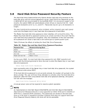
...the drive will have three attempts to be locked upon each powercycle until the correct password is only supported on either SATA port 0 (mSATA) or SATA Port 1 (onboard SATA connector). After the third unsuccessful hard disk drive password attempt, the system will halt with normal POST. Overview of ...when installed, will be accessible. 63 Table 29. The passwords are stored on resume from S3. NOTE As implemented on Intel NUC Board D54250WYB and Intel NUC Board D34010WYB, Hard Disk Drive Password Security is given. The Master Key hard disk drive password exists as an unlock...
...the drive will have three attempts to be locked upon each powercycle until the correct password is only supported on either SATA port 0 (mSATA) or SATA Port 1 (onboard SATA connector). After the third unsuccessful hard disk drive password attempt, the system will halt with normal POST. Overview of ...when installed, will be accessible. 63 Table 29. The passwords are stored on resume from S3. NOTE As implemented on Intel NUC Board D54250WYB and Intel NUC Board D34010WYB, Hard Disk Drive Password Security is given. The Master Key hard disk drive password exists as an unlock...


