
Technical Product Specification
Page 3
... Specification Changes or Clarifications Table 1 indicates the Specification Changes or Specification Clarifications that apply to the Intel® Desktop Board D33217CK. iii Errata Current characterized errata, if any, are documented in the Table 1 Audio section. Table 1. The Intel® QS77 PCH and Intel® Core™ i3-3217U processor used on the component side of Computing...
... Specification Changes or Clarifications Table 1 indicates the Specification Changes or Specification Clarifications that apply to the Intel® Desktop Board D33217CK. iii Errata Current characterized errata, if any, are documented in the Table 1 Audio section. Table 1. The Intel® QS77 PCH and Intel® Core™ i3-3217U processor used on the component side of Computing...

Technical Product Specification
Page 6
Volts. vi Voltages are the property of their respective owners. Intel Desktop Board D33217CK Technical Product Specification Other Common Notation # GB GB/s Gb/s KB Kb kb/s MB MB/s Mb Mb/s TDP xxh x.x V * Used after a signal name to indicate third-...
Volts. vi Voltages are the property of their respective owners. Intel Desktop Board D33217CK Technical Product Specification Other Common Notation # GB GB/s Gb/s KB Kb kb/s MB MB/s Mb Mb/s TDP xxh x.x V * Used after a signal name to indicate third-...

Technical Product Specification
Page 8
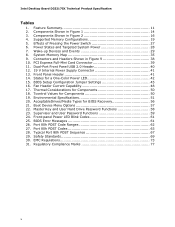
Intel Desktop Board D33217CK Technical Product Specification 2 Technical Reference 2.1 Memory Resources 33 2.1.1 Addressable Memory 33 2.1.2 Memory Map 35 2.2 Connectors and Headers 35 2.2.1 Back Panel Connectors 36 2.2.2 Connectors and Headers (... 69 5.1.2 European Union Declaration of Conformity Statement 70 5.1.3 Product Ecology Statements 71 5.1.4 EMC Regulations 73 5.1.5 ENERGY STAR* 5.2, e-Standby, and ErP Compliance 76 5.1.6 Regulatory Compliance Marks (Board Level 77 5.2 Battery Disposal Information 78 viii
Intel Desktop Board D33217CK Technical Product Specification 2 Technical Reference 2.1 Memory Resources 33 2.1.1 Addressable Memory 33 2.1.2 Memory Map 35 2.2 Connectors and Headers 35 2.2.1 Back Panel Connectors 36 2.2.2 Connectors and Headers (... 69 5.1.2 European Union Declaration of Conformity Statement 70 5.1.3 Product Ecology Statements 71 5.1.4 EMC Regulations 73 5.1.5 ENERGY STAR* 5.2, e-Standby, and ErP Compliance 76 5.1.6 Regulatory Compliance Marks (Board Level 77 5.2 Battery Disposal Information 78 viii
Technical Product Specification
Page 10
... Settings 45 16. Port 80h POST Code Ranges 62 27. Safety Standards 69 30. Effects of Pressing the Power Switch 27 6. EMC Regulations 73 31. Intel Desktop Board D33217CK Technical Product Specification Tables 1. PCI Express Full-Mini Card Connector 39 11. Tcontrol Values for a One-Color Power LED 42 15. Power States and Targeted...
... Settings 45 16. Port 80h POST Code Ranges 62 27. Safety Standards 69 30. Effects of Pressing the Power Switch 27 6. EMC Regulations 73 31. Intel Desktop Board D33217CK Technical Product Specification Tables 1. PCI Express Full-Mini Card Connector 39 11. Tcontrol Values for a One-Color Power LED 42 15. Power States and Targeted...

Technical Product Specification
Page 12
Feature Summary (continued) Hardware Monitor Subsystem Hardware monitoring subsystem, based on a Nuvoton NPCE791C embedded controller, including: • Voltage sense to detect out of range power supply voltages • Thermal sense to detect out of range thermal values • One processor fan header • Fan sense input used to monitor fan activity • Simple fan speed control 12 Intel Desktop Board D33217CK Technical Product Specification Table 2.
Feature Summary (continued) Hardware Monitor Subsystem Hardware monitoring subsystem, based on a Nuvoton NPCE791C embedded controller, including: • Voltage sense to detect out of range power supply voltages • Thermal sense to detect out of range thermal values • One processor fan header • Fan sense input used to monitor fan activity • Simple fan speed control 12 Intel Desktop Board D33217CK Technical Product Specification Table 2.

Technical Product Specification
Page 14
Table 3. Intel Desktop Board D33217CK Technical Product Specification Table 3 lists the components identified in Figure 1 Item from Figure 1 A B Description Battery Standby power LED C Processor fan header D Onboard power button E Power LED F Hard Disk Drive LED G Thermal solution 14 Components Shown in Figure 1.
Table 3. Intel Desktop Board D33217CK Technical Product Specification Table 3 lists the components identified in Figure 1 Item from Figure 1 A B Description Battery Standby power LED C Processor fan header D Onboard power button E Power LED F Hard Disk Drive LED G Thermal solution 14 Components Shown in Figure 1.
Technical Product Specification
Page 18
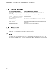
... and integrated memory controller. Refer to Section 2.5.1 on page 47 for information on power supply requirements for providing power to the processor. Intel Next Unit of Computing Board D33217CK Next Unit of Computing Board Support Available configurations for Intel Next Unit of Computing Board D33217CK Visit this board. 18 Intel Desktop Board D33217CK Technical Product Specification 1.2 Online Support To find information about...
... and integrated memory controller. Refer to Section 2.5.1 on page 47 for information on power supply requirements for providing power to the processor. Intel Next Unit of Computing Board D33217CK Next Unit of Computing Board Support Available configurations for Intel Next Unit of Computing Board D33217CK Visit this board. 18 Intel Desktop Board D33217CK Technical Product Specification 1.2 Online Support To find information about...

Technical Product Specification
Page 20
...installed or the memory capacities are equal. Technology and device width can vary from one channel to : http://support.intel.com/support/motherboards/desktop/sb /CS-025414.htm 1.4.1 Memory Configurations The processor supports the following types of both SO-DIMM channels are ... one channel to the other . Tested Memory Refer to the other but the installed memory capacity for real world applications. Intel Desktop Board D33217CK Technical Product Specification For information about ... If different speed SO-DIMMs are used between channels, the slowest memory timing will ...
...installed or the memory capacities are equal. Technology and device width can vary from one channel to : http://support.intel.com/support/motherboards/desktop/sb /CS-025414.htm 1.4.1 Memory Configurations The processor supports the following types of both SO-DIMM channels are ... one channel to the other . Tested Memory Refer to the other but the installed memory capacity for real world applications. Intel Desktop Board D33217CK Technical Product Specification For information about ... If different speed SO-DIMMs are used between channels, the slowest memory timing will ...
Technical Product Specification
Page 22
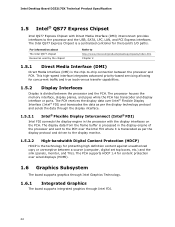
Intel Desktop Board D33217CK Technical Product Specification 1.5 Intel® QS77 Express Chipset Intel QS77 Express Chipset with the display interfaces on the PCH. For information about The Intel QS77 chipset Resources used by the chipset Refer to http://www.intel.com/products/desktop/chipsets/index.htm Chapter 2 1.5.1 Direct Media Interface (DMI) Direct Media Interface (DMI) is divided between the processor...
Intel Desktop Board D33217CK Technical Product Specification 1.5 Intel® QS77 Express Chipset Intel QS77 Express Chipset with the display interfaces on the PCH. For information about The Intel QS77 chipset Resources used by the chipset Refer to http://www.intel.com/products/desktop/chipsets/index.htm Chapter 2 1.5.1 Direct Media Interface (DMI) Direct Media Interface (DMI) is divided between the processor...
Technical Product Specification
Page 24
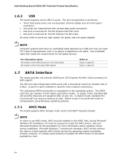
... BIOS. A point-to-point interface is as follows: • Three front panel ports (via the Intel QS77 Express Chipset. Intel Desktop Board D33217CK Technical Product Specification 1.6.2 USB The board supports seven USB 2.0 ports. The port arrangement is used . The PCH provides independent SATA ports with ...standard PCI Conventional bus resource steering is reserved for host to Figure 8, page 36 Figure 2, page 15 1.7 SATA Interface The board provides one front panel connector) • Two ports are implemented with a theoretical maximum transfer rate of the front panel USB ...
... BIOS. A point-to-point interface is as follows: • Three front panel ports (via the Intel QS77 Express Chipset. Intel Desktop Board D33217CK Technical Product Specification 1.6.2 USB The board supports seven USB 2.0 ports. The port arrangement is used . The PCH provides independent SATA ports with ...standard PCI Conventional bus resource steering is reserved for host to Figure 8, page 36 Figure 2, page 15 1.7 SATA Interface The board provides one front panel connector) • Two ports are implemented with a theoretical maximum transfer rate of the front panel USB ...
Technical Product Specification
Page 25
... (CR2032) powers the real-time clock and CMOS memory. The clock is supported by an Intel® L3310 CIO 10 Gb Controller. Figure 1 on Intel Desktop Board D33217CK as a plug and play interface. Thunderbolt technology is implemented on page 13 shows the location of... the battery. 1.9 Connectivity 1.9.1 Thunderbolt™ Technology Interface The board's Thunderbolt Technology Interface is accurate to support communications...
... (CR2032) powers the real-time clock and CMOS memory. The clock is supported by an Intel® L3310 CIO 10 Gb Controller. Figure 1 on Intel Desktop Board D33217CK as a plug and play interface. Thunderbolt technology is implemented on page 13 shows the location of... the battery. 1.9 Connectivity 1.9.1 Thunderbolt™ Technology Interface The board's Thunderbolt Technology Interface is accurate to support communications...

Technical Product Specification
Page 26
Item A B Description Processor fan header Thermal solution Figure 5. Thermal Solution and Fan Header 26 Intel Desktop Board D33217CK Technical Product Specification 1.10.1 Hardware Monitoring The hardware monitoring and fan control subsystem is based on a Nuvoton NPCE791C embedded controller, which supports the following: • ...
Item A B Description Processor fan header Thermal solution Figure 5. Thermal Solution and Fan Header 26 Intel Desktop Board D33217CK Technical Product Specification 1.10.1 Hardware Monitoring The hardware monitoring and fan control subsystem is based on a Nuvoton NPCE791C embedded controller, which supports the following: • ...
Technical Product Specification
Page 28
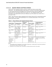
...D3 - Full power > 30 W Power < 5 W (Note 2) Power < 5 W (Note 2) Power < 5 W (Note 2) G3 - No power to disk. Intel Desktop Board D33217CK Technical Product Specification 1.11.1.1 System States and Power States Under ACPI, the operating system directs all system and device power state transitions. The operating system... sleeping state G2/S5 S0 - The operating system puts devices in boards and peripherals powered by applications. See the ACPI specification for wake-up logic, except when provided by the board along with the associated system power targets. working state. C0 - no...
...D3 - Full power > 30 W Power < 5 W (Note 2) Power < 5 W (Note 2) Power < 5 W (Note 2) G3 - No power to disk. Intel Desktop Board D33217CK Technical Product Specification 1.11.1.1 System States and Power States Under ACPI, the operating system directs all system and device power state transitions. The operating system... sleeping state G2/S5 S0 - The operating system puts devices in boards and peripherals powered by applications. See the ACPI specification for wake-up logic, except when provided by the board along with the associated system power targets. working state. C0 - no...
Technical Product Specification
Page 30
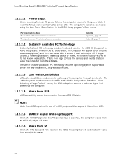
Intel Desktop Board D33217CK Technical Product Specification 1.11.2.1 Power Input When resuming from an AC power failure, the computer returns to the power state it was in before power ... the internal power connector Refer to Figure 10, page 42 Table 13, page 41 1.11.2.2 Instantly Available PC Technology Instantly Available PC technology enables the board to be set using the Last Power State feature in the S3 sleep-state, the computer will automatically wake from the S3 state. The LAN...
Intel Desktop Board D33217CK Technical Product Specification 1.11.2.1 Power Input When resuming from an AC power failure, the computer returns to the power state it was in before power ... the internal power connector Refer to Figure 10, page 42 Table 13, page 41 1.11.2.2 Instantly Available PC Technology Instantly Available PC technology enables the board to be set using the Last Power State feature in the S3 sleep-state, the computer will automatically wake from the S3 state. The LAN...
Technical Product Specification
Page 36
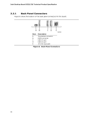
Intel Desktop Board D33217CK Technical Product Specification 2.2.1 Back Panel Connectors Figure 8 shows the location of the back panel connectors for the board. Item A B C D E Description Thunderbolt connector HDMI connector USB 2.0 port USB 2.0 port 19 V DC input jack Figure 8. Back Panel Connectors 36
Intel Desktop Board D33217CK Technical Product Specification 2.2.1 Back Panel Connectors Figure 8 shows the location of the back panel connectors for the board. Item A B C D E Description Thunderbolt connector HDMI connector USB 2.0 port USB 2.0 port 19 V DC input jack Figure 8. Back Panel Connectors 36
Technical Product Specification
Page 38
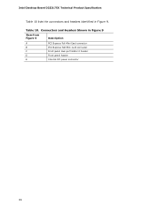
Table 10. Intel Desktop Board D33217CK Technical Product Specification Table 10 lists the connectors and headers identified in Figure 9 Item from Figure 9 Description A PCI Express Full-Mini Card connector B PCI Express Half-Mini Card connector C Front panel dual-port USB 2.0 header D Front panel header E Internal DC power connector 38 Connectors and Headers Shown in Figure 9.
Table 10. Intel Desktop Board D33217CK Technical Product Specification Table 10 lists the connectors and headers identified in Figure 9 Item from Figure 9 Description A PCI Express Full-Mini Card connector B PCI Express Half-Mini Card connector C Front panel dual-port USB 2.0 header D Front panel header E Internal DC power connector 38 Connectors and Headers Shown in Figure 9.

Technical Product Specification
Page 40
... Pin Signal Name Pin Signal Name 1 +5 V DC 2 +5 V DC 3 D− 4 D− 5 D+ 6 D+ 7 Ground 8 Ground 9 KEY (no pin) 10 No Connect 2.2.2.2 Add-in Card Connectors The board has the following add-in card connectors: • One PCI Express Half-Mini Card • One PCI Express Full-Mini Card 40 Intel Desktop Board D33217CK Technical Product Specification Table 11.
... Pin Signal Name Pin Signal Name 1 +5 V DC 2 +5 V DC 3 D− 4 D− 5 D+ 6 D+ 7 Ground 8 Ground 9 KEY (no pin) 10 No Connect 2.2.2.2 Add-in Card Connectors The board has the following add-in card connectors: • One PCI Express Half-Mini Card • One PCI Express Full-Mini Card 40 Intel Desktop Board D33217CK Technical Product Specification Table 11.
Technical Product Specification
Page 42
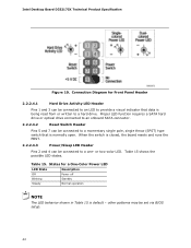
... an onboard SATA connector. 2.2.2.4.2 Reset Switch Header Pins 5 and 7 can be connected to a momentary single pole, single throw (SPST) type switch that data is default - Intel Desktop Board D33217CK Technical Product Specification Figure 10. States for Front Panel Header 2.2.2.4.1 Hard Drive Activity LED Header Pins 1 and 3 can be connected to an LED to provide...
... an onboard SATA connector. 2.2.2.4.2 Reset Switch Header Pins 5 and 7 can be connected to a momentary single pole, single throw (SPST) type switch that data is default - Intel Desktop Board D33217CK Technical Product Specification Figure 10. States for Front Panel Header 2.2.2.4.1 Hard Drive Activity LED Header Pins 1 and 3 can be connected to an LED to provide...

Technical Product Specification
Page 44
...12. Figure 12 shows the location of the BIOS Configuration Setup Jumper 44 Location of the BIOS Setup Configuration jumper. Otherwise, the board could be damaged. Table 16 describes the BIOS Setup configuration jumper settings for the three modes: normal, configure, and recovery. When...computer is powered-up, the BIOS compares the processor version and the microcode version in the BIOS and reports if the two match. Intel Desktop Board D33217CK Technical Product Specification 2.3 BIOS Setup Configuration Jumper CAUTION Do not move a jumper with the power on. Always turn off the power ...
...12. Figure 12 shows the location of the BIOS Configuration Setup Jumper 44 Location of the BIOS Setup Configuration jumper. Otherwise, the board could be damaged. Table 16 describes the BIOS Setup configuration jumper settings for the three modes: normal, configure, and recovery. When...computer is powered-up, the BIOS compares the processor version and the microcode version in the BIOS and reports if the two match. Intel Desktop Board D33217CK Technical Product Specification 2.3 BIOS Setup Configuration Jumper CAUTION Do not move a jumper with the power on. Always turn off the power ...

Technical Product Specification
Page 46
The outer dimensions are given in inches [millimeters]. Dimensions are 4.0 inches by 4.0 inches [101.60 millimeters by 101.60 millimeters]. Figure 13. Intel Desktop Board D33217CK Technical Product Specification 2.4 Mechanical Considerations 2.4.1 Form Factor The board is designed to fit into a custom chassis. Board Dimensions 46 Figure 13 illustrates the mechanical form factor for the board.
The outer dimensions are given in inches [millimeters]. Dimensions are 4.0 inches by 4.0 inches [101.60 millimeters by 101.60 millimeters]. Figure 13. Intel Desktop Board D33217CK Technical Product Specification 2.4 Mechanical Considerations 2.4.1 Form Factor The board is designed to fit into a custom chassis. Board Dimensions 46 Figure 13 illustrates the mechanical form factor for the board.


