Product Guide
Page 3
Intended Audience The Product Guide is not intended for Intel® Desktop Board D201GLY2. may not be supported without further evaluation by Intel. Preface This Product Guide gives information about how to prevent damage to important information. Intended Uses All Intel® Desktop Boards are used in homes, offices, schools, computer rooms, and similar locations. NOTE Notes call attention...
Intended Audience The Product Guide is not intended for Intel® Desktop Board D201GLY2. may not be supported without further evaluation by Intel. Preface This Product Guide gives information about how to prevent damage to important information. Intended Uses All Intel® Desktop Boards are used in homes, offices, schools, computer rooms, and similar locations. NOTE Notes call attention...
Product Guide
Page 5
... Power Indicator LED 19 LAN Wake Capabilities 20 Wake from USB 21 Wake from PS/2 Keyboard/Mouse 21 PME# Wakeup Support 21 Battery ...21 Real-Time Clock 21 2 Installing and Replacing Desktop Board Components Before You Begin 23 Installation Precautions 24 Prevent Power Supply Overload 24 Observe Safety and Regulatory Requirements 24 Installing...
... Power Indicator LED 19 LAN Wake Capabilities 20 Wake from USB 21 Wake from PS/2 Keyboard/Mouse 21 PME# Wakeup Support 21 Battery ...21 Real-Time Clock 21 2 Installing and Replacing Desktop Board Components Before You Begin 23 Installation Precautions 24 Prevent Power Supply Overload 24 Observe Safety and Regulatory Requirements 24 Installing...
Product Guide
Page 9
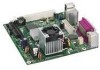
no support for Advanced Configuration and Power Interface (ACPI); Table 1 summarizes the features of Intel® Desktop Board D201GLY2. 1 Desktop Board Features This chapter briefly describes the main features of the Desktop Board. Table 1. Feature Summary Form Factor Processor Mini-ITX (171.45 millimeters [6.75 inches] x 171.45 millimeters [6.75 inches]) Intel® Celeron® processor Main Memory • One...
no support for Advanced Configuration and Power Interface (ACPI); Table 1 summarizes the features of Intel® Desktop Board D201GLY2. 1 Desktop Board Features This chapter briefly describes the main features of the Desktop Board. Table 1. Feature Summary Form Factor Processor Mini-ITX (171.45 millimeters [6.75 inches] x 171.45 millimeters [6.75 inches]) Intel® Celeron® processor Main Memory • One...
Product Guide
Page 10
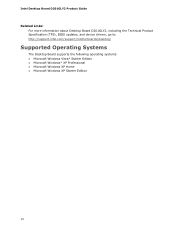
Intel Desktop Board D201GLY2 Product Guide Related Links: For more information about Desktop Board D201GLY2, including the Technical Product Specification (TPS), BIOS updates, and device drivers, go to: http://support.intel.com/support/motherboards/desktop/ Supported Operating Systems The Desktop Board supports the following operating systems: • Microsoft Windows Vista* Starter Edition • Microsoft Windows* XP Professional • Microsoft Windows XP Home • Microsoft Windows XP Starter Edition 10
Intel Desktop Board D201GLY2 Product Guide Related Links: For more information about Desktop Board D201GLY2, including the Technical Product Specification (TPS), BIOS updates, and device drivers, go to: http://support.intel.com/support/motherboards/desktop/ Supported Operating Systems The Desktop Board supports the following operating systems: • Microsoft Windows Vista* Starter Edition • Microsoft Windows* XP Professional • Microsoft Windows XP Home • Microsoft Windows XP Starter Edition 10
Product Guide
Page 12
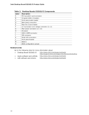
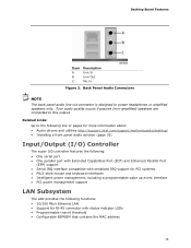
Desktop Boards D201GLY2 Components Label A B C D E F G H I J K L M N Description PCI bus add-in card connector Hi-speed USB 2.0 headers Front panel audio header Back panel connectors Rear ... jumper Related Links: Go to the following links for more information about: • Desktop Board D201GLY2 • Audio software and utilities • LAN software and drivers http://www.intel.com/design/motherbd http://support.intel.com/support/motherboards/desktop http://www.intel.com/design/motherbd http://www.intel.com/design/motherbd 12 Intel Desktop Board D201GLY2 Product Guide Table 2.
Desktop Boards D201GLY2 Components Label A B C D E F G H I J K L M N Description PCI bus add-in card connector Hi-speed USB 2.0 headers Front panel audio header Back panel connectors Rear ... jumper Related Links: Go to the following links for more information about: • Desktop Board D201GLY2 • Audio software and utilities • LAN software and drivers http://www.intel.com/design/motherbd http://support.intel.com/support/motherboards/desktop http://www.intel.com/design/motherbd http://www.intel.com/design/motherbd 12 Intel Desktop Board D201GLY2 Product Guide Table 2.
Product Guide
Page 13
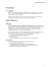
...Desktop Board has one 240-pin Double Data Rate 2 (DDR2) SDRAM Dual Inline Memory Module (DIMM) connector with DIMMs that support the Serial Presence Detect (SPD) data structure. The processor is soldered to configure the memory controller for more information about: • The latest list of tested memory, http://support.intel.com/support/motherboards/desktop.../ • SDRAM specifications, http://www.intel.com/technology/memory/ • Installing memory, page 27 in damage ...
...Desktop Board has one 240-pin Double Data Rate 2 (DDR2) SDRAM Dual Inline Memory Module (DIMM) connector with DIMMs that support the Serial Presence Detect (SPD) data structure. The processor is soldered to configure the memory controller for more information about: • The latest list of tested memory, http://support.intel.com/support/motherboards/desktop.../ • SDRAM specifications, http://www.intel.com/technology/memory/ • Installing memory, page 27 in damage ...
Product Guide
Page 14
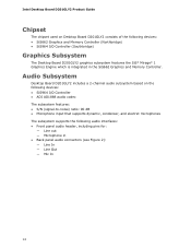
...panel audio header, including pins for: ― Line out ― Microphone in the SiS662 Graphics and Memory Controller. Intel Desktop Board D201GLY2 Product Guide Chipset The chipset used on the following devices: • SiS964 I/O Controller • ADI AD1888 audio...90 dB • Microphone input that supports dynamic, condenser, and electret microphones The subsystem supports the following devices: • SiS662 Graphics and Memory Controller (Northbridge) • SiS964 I/O Controller (Southbridge) Graphics Subsystem The Desktop Board D201GLY2 graphics subsystem features the SiS* ...
...panel audio header, including pins for: ― Line out ― Microphone in the SiS662 Graphics and Memory Controller. Intel Desktop Board D201GLY2 Product Guide Chipset The chipset used on the following devices: • SiS964 I/O Controller • ADI AD1888 audio...90 dB • Microphone input that supports dynamic, condenser, and electret microphones The subsystem supports the following devices: • SiS662 Graphics and Memory Controller (Northbridge) • SiS964 I/O Controller (Southbridge) Graphics Subsystem The Desktop Board D201GLY2 graphics subsystem features the SiS* ...
Product Guide
Page 15
.... Related Links: Go to the following link or pages for more information about: • Audio drivers and utilities http://support.intel.com/support/motherboards/desktop/ • Installing a front panel audio solution (page 33) Input/Output (I/O) Controller The super I/O controller features the ... management support LAN Subsystem The LAN provides the following functions: • 10/100 Mb/s Ethernet LAN • Support for RJ-45 connector with status indicator LEDs • Programmable transit threshold • Configurable EEPROM that contains the MAC address 15 Desktop Board Features...
.... Related Links: Go to the following link or pages for more information about: • Audio drivers and utilities http://support.intel.com/support/motherboards/desktop/ • Installing a front panel audio solution (page 33) Input/Output (I/O) Controller The super I/O controller features the ... management support LAN Subsystem The LAN provides the following functions: • 10/100 Mb/s Ethernet LAN • Support for RJ-45 connector with status indicator LEDs • Programmable transit threshold • Configurable EEPROM that contains the MAC address 15 Desktop Board Features...
Product Guide
Page 16
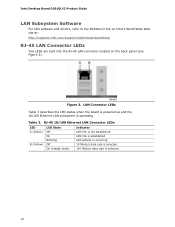
... powered up and the 10/100 Ethernet LAN subsystem is selected 16 Intel Desktop Board D201GLY2 Product Guide LAN Subsystem Software For LAN software and drivers, refer to the D201GLY2 link on Intel's World Wide Web site at: http://support.intel.com/support/motherboards/desktop RJ-45 LAN Connector LEDs Two LEDs are built into the RJ-45 LAN...
... powered up and the 10/100 Ethernet LAN subsystem is selected 16 Intel Desktop Board D201GLY2 Product Guide LAN Subsystem Software For LAN software and drivers, refer to the D201GLY2 link on Intel's World Wide Web site at: http://support.intel.com/support/motherboards/desktop RJ-45 LAN Connector LEDs Two LEDs are built into the RJ-45 LAN...
Product Guide
Page 17
... one PCI add-in the BIOS reverts all USB 2.0 ports to accommodate operating systems that do not support USB 2.0. Expandability The Desktop Board supports one device per channel. Desktop Board Features Hi-Speed USB 2.0 Support NOTE Computer systems that have an unshielded cable attached to a USB port might not meet FCC Class... B requirements, even if no device or a low-speed USB device is attached to two internal USB 2.0 headers). The Desktop Board supports up to six USB 2.0 ports (two ports routed to the back panel and four ports routed to the cable. BIOS The BIOS ...
... one PCI add-in the BIOS reverts all USB 2.0 ports to accommodate operating systems that do not support USB 2.0. Expandability The Desktop Board supports one device per channel. Desktop Board Features Hi-Speed USB 2.0 Support NOTE Computer systems that have an unshielded cable attached to a USB port might not meet FCC Class... B requirements, even if no device or a low-speed USB device is attached to two internal USB 2.0 headers). The Desktop Board supports up to six USB 2.0 ports (two ports routed to the back panel and four ports routed to the cable. BIOS The BIOS ...
Product Guide
Page 18
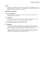
...The supervisor password gives unrestricted access to view and change all Setup options. You do not need to boot the computer. Intel Desktop Board D201GLY2 Product Guide IDE Auto Configuration If you install an IDE device (such as a hard drive) in your computer, the... password. Power Management Features Power management is set, pressing at several levels, including: • Advanced Configuration and Power Interface (ACPI) • Hardware support: ― Power connectors ― Fan headers ― +5 V standby power indicator LED ― LAN Wake capabilities ― Wake from USB ...
...The supervisor password gives unrestricted access to view and change all Setup options. You do not need to boot the computer. Intel Desktop Board D201GLY2 Product Guide IDE Auto Configuration If you install an IDE device (such as a hard drive) in your computer, the... password. Power Management Features Power management is set, pressing at several levels, including: • Advanced Configuration and Power Interface (ACPI) • Hardware support: ― Power connectors ― Fan headers ― +5 V standby power indicator LED ― LAN Wake capabilities ― Wake from USB ...
Product Guide
Page 19
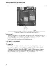
...the operating system direct control over the power management and Plug and Play functions of ACPI with the Desktop Board requires an operating system that provides full ACPI support. The Desktop Board's standby power indicator, shown in Figure 4, is lit when there is still lit, disconnect the... power cord before installing or removing any attached devices. Fan Headers The Desktop Board has a 3-pin processor fan header and a 3-...
...the operating system direct control over the power management and Plug and Play functions of ACPI with the Desktop Board requires an operating system that provides full ACPI support. The Desktop Board's standby power indicator, shown in Figure 4, is lit when there is still lit, disconnect the... power cord before installing or removing any attached devices. Fan Headers The Desktop Board has a 3-pin processor fan header and a 3-...
Product Guide
Page 20
...product, and selecting Product Documentation from the left-hand menu: http://support.intel.com/support/motherboards/desktop/ LAN Wake Capabilities CAUTION For LAN wake capabilities, the 5 V standby line for the Desktop Board, refer to the Technical Product Specification by going to provide adequate ...that powers up of delivering adequate +5 V standby current. LAN wakeup capabilities enable remote wake-up the computer. 20 Intel Desktop Board D201GLY2 Product Guide Figure 4. Location of the Standby Power Indicator Related Links: For more information on standby current requirements ...
...product, and selecting Product Documentation from the left-hand menu: http://support.intel.com/support/motherboards/desktop/ LAN Wake Capabilities CAUTION For LAN wake capabilities, the 5 V standby line for the Desktop Board, refer to the Technical Product Specification by going to provide adequate ...that powers up of delivering adequate +5 V standby current. LAN wakeup capabilities enable remote wake-up the computer. 20 Intel Desktop Board D201GLY2 Product Guide Figure 4. Location of the Standby Power Indicator Related Links: For more information on standby current requirements ...
Product Guide
Page 21
Real-Time Clock The Desktop Board has a time-of a USB peripheral that supports wake from an ACPI S1 state. USB bus activity wakes the computer from USB. Battery A battery on the PCI bus is asserted, the computer wakes from an ACPI S1 state. Desktop Board Features Wake from USB NOTE Wake from USB requires... the use of -day clock and 100-year calendar. Go to replace the battery. PME# Wakeup Support When the PME# signal on the Desktop Board keeps the values in CMOS RAM and the clock current when the computer is turned off . The battery on how to ...
Real-Time Clock The Desktop Board has a time-of a USB peripheral that supports wake from an ACPI S1 state. USB bus activity wakes the computer from USB. Battery A battery on the PCI bus is asserted, the computer wakes from an ACPI S1 state. Desktop Board Features Wake from USB NOTE Wake from USB requires... the use of -day clock and 100-year calendar. Go to replace the battery. PME# Wakeup Support When the PME# signal on the Desktop Board keeps the values in CMOS RAM and the clock current when the computer is turned off . The battery on how to ...
Product Guide
Page 27
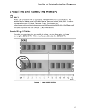
Installing and Replacing Desktop Board Components Installing and Removing Memory NOTE To be fully compliant with all applicable Intel SDRAM memory specifications, the boards require DIMMs that support the Serial Presence Detect (SPD) data structure. Installing DIMMs To make sure you have the correct DIMM, place it on the illustration in ... 27 Figure 7. All the notches should match the DDR2 DIMM. You can access the PC Serial Presence Detect Specification at: http://www.intel.com/technology/memory/ddr/specs/dda18c32_64_128x72ag_a.pdf The Desktop Board has one 240-pin DDR2 DIMM socket.
Installing and Replacing Desktop Board Components Installing and Removing Memory NOTE To be fully compliant with all applicable Intel SDRAM memory specifications, the boards require DIMMs that support the Serial Presence Detect (SPD) data structure. Installing DIMMs To make sure you have the correct DIMM, place it on the illustration in ... 27 Figure 7. All the notches should match the DDR2 DIMM. You can access the PC Serial Presence Detect Specification at: http://www.intel.com/technology/memory/ddr/specs/dda18c32_64_128x72ag_a.pdf The Desktop Board has one 240-pin DDR2 DIMM socket.
Product Guide
Page 29
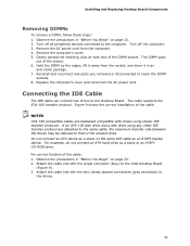
... the socket. 6. NOTES ATA-100 compatible cables are attached to the same cable, the maximum transfer rate between the drives may be reduced to the Intel Desktop Board (Figure 9). 3. Remove the computer's cover. 5. Remove the AC power cord from the socket, and store it in "Before You Begin" on page 23. 2. ...Gently spread the retaining clips at each end of the cable: 1. The cable supports the ATA-100 transfer protocol. Do not connect an ATA device as a slave to the drives. 29 For example, do not connect an ATA hard...
... the socket. 6. NOTES ATA-100 compatible cables are attached to the same cable, the maximum transfer rate between the drives may be reduced to the Intel Desktop Board (Figure 9). 3. Remove the computer's cover. 5. Remove the AC power cord from the socket, and store it in "Before You Begin" on page 23. 2. ...Gently spread the retaining clips at each end of the cable: 1. The cable supports the ATA-100 transfer protocol. Do not connect an ATA device as a slave to the drives. 29 For example, do not connect an ATA hard...
Product Guide
Page 31
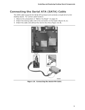
Attach the locking cable end to the connector on page 23. 2. Connecting the Serial ATA Cable 31 Observe the precautions in "Before You Begin" on the board (Figure 10, A). 3. For correct cable function: 1. Attach the cable end without the lock to the desktop board. Installing and Replacing Desktop Board Components Connecting the Serial ATA (SATA) Cable The SATA cable supports the Serial ATA protocol and connects a single drive to the drive (Figure 10, B). Figure 10.
Attach the locking cable end to the connector on page 23. 2. Connecting the Serial ATA Cable 31 Observe the precautions in "Before You Begin" on the board (Figure 10, A). 3. For correct cable function: 1. Attach the cable end without the lock to the desktop board. Installing and Replacing Desktop Board Components Connecting the Serial ATA (SATA) Cable The SATA cable supports the Serial ATA protocol and connects a single drive to the drive (Figure 10, B). Figure 10.
Product Guide
Page 45
... file. This chapter tells you need to update the BIOS. Navigate to the Intel World Wide Web site: http://support.intel.com/support/motherboards/desktop/ 2. The Iflash BIOS update file contains: • New BIOS file • Intel Flash Memory Update Utility 45 3 Updating the BIOS The BIOS Setup program can ... section to complete the BIOS update. Download the file to your hard drive where it was saved. Updating the BIOS with the Intel Express BIOS Update utility: 1. Follow the instructions provided in the Windows environment. You can update to recover the BIOS if an update...
... file. This chapter tells you need to update the BIOS. Navigate to the Intel World Wide Web site: http://support.intel.com/support/motherboards/desktop/ 2. The Iflash BIOS update file contains: • New BIOS file • Intel Flash Memory Update Utility 45 3 Updating the BIOS The BIOS Setup program can ... section to complete the BIOS update. Download the file to your hard drive where it was saved. Updating the BIOS with the Intel Express BIOS Update utility: 1. Follow the instructions provided in the Windows environment. You can update to recover the BIOS if an update...
Product Guide
Page 46
... properly. however, if an interruption occurs, the BIOS could be extracted locally to your computer supplier or by navigating to the Desktop Board D201GLY2 page on the Intel World Wide Web site at: http://support.intel.com/support/motherboards/desktop Navigate to the D201GLY2 page, click "[view] Latest BIOS updates," and select the Iflash BIOS Update utility file.
... properly. however, if an interruption occurs, the BIOS could be extracted locally to your computer supplier or by navigating to the Desktop Board D201GLY2 page on the Intel World Wide Web site at: http://support.intel.com/support/motherboards/desktop Navigate to the D201GLY2 page, click "[view] Latest BIOS updates," and select the Iflash BIOS Update utility file.


