Product Guide
Page 6
Intel Desktop Board D201GLY2 Product Guide Connecting the Front Panel Header 34 Connecting the Chassis Fan 35 Connecting Supply Power Cables 36 Setting the Desktop Board Jumpers 37 Front Panel Audio Header/Jumper Block 37 BIOS Configuration Jumper 38 Clearing Passwords 39 Replacing the Battery 40 3 Updating the BIOS Updating the BIOS with the Intel® Express BIOS Update...
Intel Desktop Board D201GLY2 Product Guide Connecting the Front Panel Header 34 Connecting the Chassis Fan 35 Connecting Supply Power Cables 36 Setting the Desktop Board Jumpers 37 Front Panel Audio Header/Jumper Block 37 BIOS Configuration Jumper 38 Clearing Passwords 39 Replacing the Battery 40 3 Updating the BIOS Updating the BIOS with the Intel® Express BIOS Update...
Product Guide
Page 7
Intel Desktop Board D201GLY2 Components 11 2. Connecting the Serial ATA Cable 31 11. Internal Headers 32 12. Connecting a 2 x 10 or 2 x 12 Power Supply Cable 36 14. Desktop Board D201GLY2 China RoHS Material Self Declaration Table 57 Tables 1. RJ-45 10/100 Ethernet LAN Connector LEDs ... RoHS Environmentally Friendly Use Period Mark 56 14. Use DDR2 DIMMs 27 8. Front-panel Power LED Blink Codes 47 10. Lead-Free Second Level Interconnect Marks 55 13. Desktop Boards D201GLY2 Components 12 3. Connecting the IDE Cable 30 10. BIOS Error Messages 47 11. Removing...
Intel Desktop Board D201GLY2 Components 11 2. Connecting the Serial ATA Cable 31 11. Internal Headers 32 12. Connecting a 2 x 10 or 2 x 12 Power Supply Cable 36 14. Desktop Board D201GLY2 China RoHS Material Self Declaration Table 57 Tables 1. RJ-45 10/100 Ethernet LAN Connector LEDs ... RoHS Environmentally Friendly Use Period Mark 56 14. Use DDR2 DIMMs 27 8. Front-panel Power LED Blink Codes 47 10. Lead-Free Second Level Interconnect Marks 55 13. Desktop Boards D201GLY2 Components 12 3. Connecting the IDE Cable 30 10. BIOS Error Messages 47 11. Removing...
Product Guide
Page 9
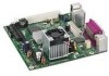
...; PS/2* keyboard and mouse ports • Intel® BIOS • Support for SMBIOS • Intel® Rapid BIOS Boot • Intel® Express BIOS Update LAN Support • 10/100 Mb/s LAN Subsystem Power Management • Support for Advanced Configuration and Power Interface (ACPI); 1 Desktop Board Features This chapter briefly describes the main features of... Peripheral Interfaces BIOS • Six USB 2.0 ports ― Two ports routed to the back panel ― Four ports routed to 1 GB of Intel® Desktop Board D201GLY2. Table 1 summarizes the features of the...
...; PS/2* keyboard and mouse ports • Intel® BIOS • Support for SMBIOS • Intel® Rapid BIOS Boot • Intel® Express BIOS Update LAN Support • 10/100 Mb/s LAN Subsystem Power Management • Support for Advanced Configuration and Power Interface (ACPI); 1 Desktop Board Features This chapter briefly describes the main features of... Peripheral Interfaces BIOS • Six USB 2.0 ports ― Two ports routed to the back panel ― Four ports routed to 1 GB of Intel® Desktop Board D201GLY2. Table 1 summarizes the features of the...
Product Guide
Page 12
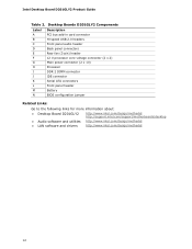
... power connector (2 x 10) Processor DDR 2 DIMM connector IDE connector Serial ATA connectors Front panel header Battery BIOS configuration jumper Related Links: Go to the following links for more information about: • Desktop Board D201GLY2 • Audio software and utilities • LAN software and drivers http://www.intel.com/design/motherbd http://support.intel.com/support/motherboards/desktop http...
... power connector (2 x 10) Processor DDR 2 DIMM connector IDE connector Serial ATA connectors Front panel header Battery BIOS configuration jumper Related Links: Go to the following links for more information about: • Desktop Board D201GLY2 • Audio software and utilities • LAN software and drivers http://www.intel.com/design/motherbd http://support.intel.com/support/motherboards/desktop http...
Product Guide
Page 13
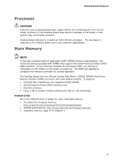
...the Serial Presence Detect (SPD) data structure. Desktop Board Features Processor CAUTION Failure to use an appropriate power supply and/or not connecting the 12 V (2 x 2) power connector to the Desktop Board may not function properly. The processor is ...Desktop Board D201GLY2 includes an Intel Celeron processor. It supports: • 533/400 MHz unbuffered, non-registered DDR2 DIMMs • Serial Presence Detect (SPD) memory only • Non-ECC memory • Up to 1 GB of tested memory, http://support.intel.com/support/motherboards/desktop/ • SDRAM specifications, http://www.intel...
...the Serial Presence Detect (SPD) data structure. Desktop Board Features Processor CAUTION Failure to use an appropriate power supply and/or not connecting the 12 V (2 x 2) power connector to the Desktop Board may not function properly. The processor is ...Desktop Board D201GLY2 includes an Intel Celeron processor. It supports: • 533/400 MHz unbuffered, non-registered DDR2 DIMMs • Serial Presence Detect (SPD) memory only • Non-ECC memory • Up to 1 GB of tested memory, http://support.intel.com/support/motherboards/desktop/ • SDRAM specifications, http://www.intel...
Product Guide
Page 16
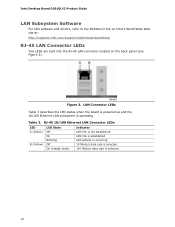
...data rate is operating. Table 3. Figure 3. Intel Desktop Board D201GLY2 Product Guide LAN Subsystem Software For LAN software and drivers, refer to the D201GLY2 link on Intel's World Wide Web site at: http://support.intel.com/support/motherboards/desktop RJ-45 LAN Connector LEDs Two LEDs are ...built into the RJ-45 LAN connector located on the back panel (see Figure 3). LAN Connector LEDs Table 3 describes the LED states when the board is powered...
...data rate is operating. Table 3. Figure 3. Intel Desktop Board D201GLY2 Product Guide LAN Subsystem Software For LAN software and drivers, refer to the D201GLY2 link on Intel's World Wide Web site at: http://support.intel.com/support/motherboards/desktop RJ-45 LAN Connector LEDs Two LEDs are ...built into the RJ-45 LAN connector located on the back panel (see Figure 3). LAN Connector LEDs Table 3 describes the LED states when the board is powered...
Product Guide
Page 18
...booting the computer, with the following restrictions: • The supervisor password gives unrestricted access to boot the computer. Intel Desktop Board D201GLY2 Product Guide IDE Auto Configuration If you install an IDE device (such as a hard drive) in your computer,...program after installing an IDE device. Power Management Features Power management is set, pressing at several levels, including: • Advanced Configuration and Power Interface (ACPI) • Hardware support: ― Power connectors ― Fan headers ― +5 V standby power indicator LED ― LAN Wake ...
...booting the computer, with the following restrictions: • The supervisor password gives unrestricted access to boot the computer. Intel Desktop Board D201GLY2 Product Guide IDE Auto Configuration If you install an IDE device (such as a hard drive) in your computer,...program after installing an IDE device. Power Management Features Power management is set, pressing at several levels, including: • Advanced Configuration and Power Interface (ACPI) • Hardware support: ― Power connectors ― Fan headers ― +5 V standby power indicator LED ― LAN Wake ...
Product Guide
Page 20
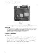
...: http://support.intel.com/support/motherboards/desktop/ LAN Wake Capabilities CAUTION For LAN wake capabilities, the 5 V standby line for the Desktop Board, refer to the Technical Product Specification by going to provide adequate standby current when using this feature can damage the power supply. LAN wakeup capabilities enable remote wake-up the computer. 20 Intel Desktop Board D201GLY2 Product Guide...
...: http://support.intel.com/support/motherboards/desktop/ LAN Wake Capabilities CAUTION For LAN wake capabilities, the 5 V standby line for the Desktop Board, refer to the Technical Product Specification by going to provide adequate standby current when using this feature can damage the power supply. LAN wakeup capabilities enable remote wake-up the computer. 20 Intel Desktop Board D201GLY2 Product Guide...

Product Guide
Page 24
... Safety and Regulatory Requirements Read and adhere to qualified technical personnel. Intel Desktop Board D201GLY2 Product Guide Installation Precautions When you install and test the Intel Desktop Board, observe all the modules within the computer is less than the output current rating of each of the power supplies output circuits. If you do not follow these instructions and...
... Safety and Regulatory Requirements Read and adhere to qualified technical personnel. Intel Desktop Board D201GLY2 Product Guide Installation Precautions When you install and test the Intel Desktop Board, observe all the modules within the computer is less than the output current rating of each of the power supplies output circuits. If you do not follow these instructions and...
Product Guide
Page 26
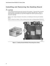
... mounting screw holes for instructions on installing and removing the Desktop Board. Figure 6. Desktop Board D201GLY2 Mounting Screw Holes 26 Failure to your chassis manual for Desktop Board D201GLY2. Intel Desktop Board D201GLY2 Product Guide Installing and Removing the Desktop Board CAUTION Only qualified technical personnel should do this procedure. Disconnect the computer from its power source before you open the computer can result in...
... mounting screw holes for instructions on installing and removing the Desktop Board. Figure 6. Desktop Board D201GLY2 Mounting Screw Holes 26 Failure to your chassis manual for Desktop Board D201GLY2. Intel Desktop Board D201GLY2 Product Guide Installing and Removing the Desktop Board CAUTION Only qualified technical personnel should do this procedure. Disconnect the computer from its power source before you open the computer can result in...
Product Guide
Page 28
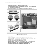
...edge of the DIMM into place. Make sure the clips are pushed outward to the computer. Turn off the computer and disconnect the AC power cord. 3. Insert the bottom edge of the DIMM with the key in the socket (see Figure 8). Replace the computer's cover and reconnect ...DIMM until the retaining clips snap into the socket. 8. Figure 8. Holding the DIMM by the edges, remove it from its anti-static package. 6. Intel Desktop Board D201GLY2 Product Guide 1. Position the DIMM above the socket. When the DIMM is inserted, push down on the top edge of the DIMM socket are firmly...
...edge of the DIMM into place. Make sure the clips are pushed outward to the computer. Turn off the computer and disconnect the AC power cord. 3. Insert the bottom edge of the DIMM with the key in the socket (see Figure 8). Replace the computer's cover and reconnect ...DIMM until the retaining clips snap into the socket. 8. Figure 8. Holding the DIMM by the edges, remove it from its anti-static package. 6. Intel Desktop Board D201GLY2 Product Guide 1. Position the DIMM above the socket. When the DIMM is inserted, push down on the top edge of the DIMM socket are firmly...
Product Guide
Page 34
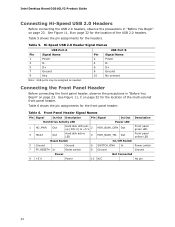
...Begin" on page 23. Hi-Speed USB 2.0 Header Signal Names USB Port A USB Port B Pin Signal Name 1 Power 3 D- 5 D+ 7 Ground 9 Key Pin Signal Name 2 Power 4 D- 6 D+ 8 Ground 10 No connect Note: USB ports may be assigned as needed. Front Panel Header ... panel yellow LED Reset Switch On/Off Switch 5 Ground Ground 6 SWITCH_ON# In Power switch 7 FP_RESET# In Reset switch 8 Ground Ground Power Not Connected 9 +5 V Power 10 N/C No pin 34 Intel Desktop Board D201GLY2 Product Guide Connecting Hi-Speed USB 2.0 Headers Before connecting the USB 2.0 headers, ...
...Begin" on page 23. Hi-Speed USB 2.0 Header Signal Names USB Port A USB Port B Pin Signal Name 1 Power 3 D- 5 D+ 7 Ground 9 Key Pin Signal Name 2 Power 4 D- 6 D+ 8 Ground 10 No connect Note: USB ports may be assigned as needed. Front Panel Header ... panel yellow LED Reset Switch On/Off Switch 5 Ground Ground 6 SWITCH_ON# In Power switch 7 FP_RESET# In Reset switch 8 Ground Ground Power Not Connected 9 +5 V Power 10 N/C No pin 34 Intel Desktop Board D201GLY2 Product Guide Connecting Hi-Speed USB 2.0 Headers Before connecting the USB 2.0 headers, ...
Product Guide
Page 36
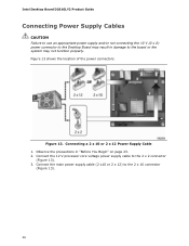
...) to the 2 x 2 connector (Figure 13). 3. Connect the 12 V processor core voltage power supply cable to the 2 x 10 connector (Figure 13). 36 Intel Desktop Board D201GLY2 Product Guide Connecting Power Supply Cables CAUTION Failure to use an appropriate power supply and/or not connecting the 12 V (2 x 2) power connector to the Desktop Board may result in "Before You Begin" on page 23. 2.
...) to the 2 x 2 connector (Figure 13). 3. Connect the 12 V processor core voltage power supply cable to the 2 x 10 connector (Figure 13). 36 Intel Desktop Board D201GLY2 Product Guide Connecting Power Supply Cables CAUTION Failure to use an appropriate power supply and/or not connecting the 12 V (2 x 2) power connector to the Desktop Board may result in "Before You Begin" on page 23. 2.
Product Guide
Page 38
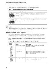
... the jumpers are removed and this menu to the back panel connectors. Table 8. Configure (2-3) After the Power-On Self-Test (POST) runs, the BIOS displays the Maintenance Menu. Table 8 shows the jumper settings for booting. Intel Desktop Board D201GLY2 Product Guide Table 7 describes the two configurations of this connector when no jumpers are installed. Use...
... the jumpers are removed and this menu to the back panel connectors. Table 8. Configure (2-3) After the Power-On Self-Test (POST) runs, the BIOS displays the Maintenance Menu. Table 8 shows the jumper settings for booting. Intel Desktop Board D201GLY2 Product Guide Table 7 describes the two configurations of this connector when no jumpers are installed. Use...
Product Guide
Page 40
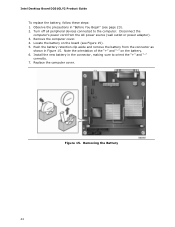
...Setup program settings stored in CMOS RAM (for example, the date and time) might not be in , the standby current from the power supply extends the life of three years. CAUTION Risk of explosion if the battery is not plugged into a wall socket, the battery...tre recyclées dans la mesure du possible. VORSICHT Bei falschem Einsetzen einer neuen Batterie besteht Explosionsgefahr. Intel Desktop Board D201GLY2 Product Guide Replacing the Battery A coin-cell battery (CR2032) powers the real-time clock and CMOS memory. Disposal of the battery. PRECAUTION Risque d'explosion si la pile ...
...Setup program settings stored in CMOS RAM (for example, the date and time) might not be in , the standby current from the power supply extends the life of three years. CAUTION Risk of explosion if the battery is not plugged into a wall socket, the battery...tre recyclées dans la mesure du possible. VORSICHT Bei falschem Einsetzen einer neuen Batterie besteht Explosionsgefahr. Intel Desktop Board D201GLY2 Product Guide Replacing the Battery A coin-cell battery (CR2032) powers the real-time clock and CMOS memory. Disposal of the battery. PRECAUTION Risque d'explosion si la pile ...
Product Guide
Page 44
... in "Before You Begin" (see Figure 15). 5. Locate the battery on the battery. 6. Figure 15. Disconnect the computer's power cord from the connector as shown in Figure 15. Remove the computer cover. 4. Intel Desktop Board D201GLY2 Product Guide To replace the battery, follow these steps: 1. Observe the precautions in the connector, making sure to the...
... in "Before You Begin" (see Figure 15). 5. Locate the battery on the battery. 6. Figure 15. Disconnect the computer's power cord from the connector as shown in Figure 15. Remove the computer cover. 4. Intel Desktop Board D201GLY2 Product Guide To replace the battery, follow these steps: 1. Observe the precautions in the connector, making sure to the...
Product Guide
Page 45
... Wide Web site: http://support.intel.com/support/motherboards/desktop/ 2. Download the file to your hard drive where it was saved. Obtaining the BIOS Update File You can access the BIOS Setup program by pressing the key after the Power-On Self-Test (POST) memory test begins and before the operating... the BIOS with the Intel® Express BIOS Update Utility With the Intel Express BIOS Update utility you need to update the BIOS by using the Iflash Memory Update Utility. You can update to a new version of use the information in the dialog boxes to the D201GLY2 page, click "[view]...
... Wide Web site: http://support.intel.com/support/motherboards/desktop/ 2. Download the file to your hard drive where it was saved. Obtaining the BIOS Update File You can access the BIOS Setup program by pressing the key after the Power-On Self-Test (POST) memory test begins and before the operating... the BIOS with the Intel® Express BIOS Update Utility With the Intel Express BIOS Update utility you need to update the BIOS by using the Iflash Memory Update Utility. You can update to a new version of use the information in the dialog boxes to the D201GLY2 page, click "[view]...

