Product Guide
Page 5
... 20 Wake from USB 21 Wake from PS/2 Keyboard/Mouse 21 PME# Wakeup Support 21 Battery ...21 Real-Time Clock 21 2 Installing and Replacing Desktop Board Components Before You Begin 23 Installation Precautions 24 Prevent Power Supply Overload 24 Observe Safety and Regulatory Requirements 24 Installing the I/O Shield 25 Installing and Removing the...
... 20 Wake from USB 21 Wake from PS/2 Keyboard/Mouse 21 PME# Wakeup Support 21 Battery ...21 Real-Time Clock 21 2 Installing and Replacing Desktop Board Components Before You Begin 23 Installation Precautions 24 Prevent Power Supply Overload 24 Observe Safety and Regulatory Requirements 24 Installing the I/O Shield 25 Installing and Removing the...
Product Guide
Page 6
Intel Desktop Board D201GLY2 Product Guide Connecting the Front Panel Header 34 Connecting the Chassis Fan 35 Connecting Supply Power Cables 36 Setting the Desktop Board Jumpers 37 Front Panel Audio Header/Jumper Block 37 BIOS Configuration Jumper 38 Clearing Passwords 39 Replacing the Battery 40 3 Updating the BIOS Updating the BIOS with the Intel® Express BIOS Update...
Intel Desktop Board D201GLY2 Product Guide Connecting the Front Panel Header 34 Connecting the Chassis Fan 35 Connecting Supply Power Cables 36 Setting the Desktop Board Jumpers 37 Front Panel Audio Header/Jumper Block 37 BIOS Configuration Jumper 38 Clearing Passwords 39 Replacing the Battery 40 3 Updating the BIOS Updating the BIOS with the Intel® Express BIOS Update...
Product Guide
Page 7
... 9 2. Front Panel Audio Header Signal Names 33 5. EMC Regulations 58 15. Desktop Boards D201GLY2 Components 12 3. Lead-Free Second Level Interconnect Marks 55 13. LAN Connector LEDs 16 4. Location of the Standby Power Indicator 20 5. Front Panel Audio Header/Jumper Block 38 8. Intel Desktop Board D201GLY2 Components 11 2. Connecting the IDE Cable 30 10. Back Panel Audio Connectors...
... 9 2. Front Panel Audio Header Signal Names 33 5. EMC Regulations 58 15. Desktop Boards D201GLY2 Components 12 3. Lead-Free Second Level Interconnect Marks 55 13. LAN Connector LEDs 16 4. Location of the Standby Power Indicator 20 5. Front Panel Audio Header/Jumper Block 38 8. Intel Desktop Board D201GLY2 Components 11 2. Connecting the IDE Cable 30 10. Back Panel Audio Connectors...
Product Guide
Page 9
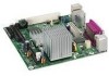
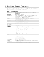
... • Intel® BIOS • Support for SMBIOS • Intel® Rapid BIOS Boot • Intel® Express BIOS Update LAN Support • 10/100 Mb/s LAN Subsystem Power Management • Support for S3 • Wake on USB, PCI, PS/2, LAN, and front panel 9 1 Desktop Board Features This chapter briefly describes the main features of Intel® Desktop Board D201GLY2.
... • Intel® BIOS • Support for SMBIOS • Intel® Rapid BIOS Boot • Intel® Express BIOS Update LAN Support • 10/100 Mb/s LAN Subsystem Power Management • Support for S3 • Wake on USB, PCI, PS/2, LAN, and front panel 9 1 Desktop Board Features This chapter briefly describes the main features of Intel® Desktop Board D201GLY2.
Product Guide
Page 12
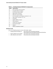
... power connector (2 x 10) Processor DDR 2 DIMM connector IDE connector Serial ATA connectors Front panel header Battery BIOS configuration jumper Related Links: Go to the following links for more information about: • Desktop Board D201GLY2 • Audio software and utilities • LAN software and drivers http://www.intel.com/design/motherbd http://support.intel.com/support/motherboards/desktop http...
... power connector (2 x 10) Processor DDR 2 DIMM connector IDE connector Serial ATA connectors Front panel header Battery BIOS configuration jumper Related Links: Go to the following links for more information about: • Desktop Board D201GLY2 • Audio software and utilities • LAN software and drivers http://www.intel.com/design/motherbd http://support.intel.com/support/motherboards/desktop http...
Product Guide
Page 13
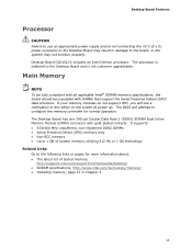
... of system memory utilizing 512 Mb or 1 Gb technology Related Links: Go to this effect on the screen at power up. The Desktop Board has one 240-pin Double Data Rate 2 (DDR2) SDRAM Dual Inline Memory Module (DIMM) connector with DIMMs that... memory, http://support.intel.com/support/motherboards/desktop/ • SDRAM specifications, http://www.intel.com/technology/memory/ • Installing memory, page 27 in damage to the Desktop Board and is not customer upgradeable. Desktop Board D201GLY2 includes an Intel Celeron processor. The processor is soldered to the board, or the system ...
... of system memory utilizing 512 Mb or 1 Gb technology Related Links: Go to this effect on the screen at power up. The Desktop Board has one 240-pin Double Data Rate 2 (DDR2) SDRAM Dual Inline Memory Module (DIMM) connector with DIMMs that... memory, http://support.intel.com/support/motherboards/desktop/ • SDRAM specifications, http://www.intel.com/technology/memory/ • Installing memory, page 27 in damage to the Desktop Board and is not customer upgradeable. Desktop Board D201GLY2 includes an Intel Celeron processor. The processor is soldered to the board, or the system ...
Product Guide
Page 15
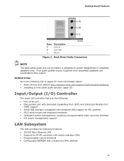
...if passive (non-amplified) speakers are connected to the following link or pages for more information about: • Audio drivers and utilities http://support.intel.com/support/motherboards/desktop/ • Installing a front panel audio solution (page 33) Input/Output (I/O) Controller The super I/O controller features the following: • One serial...: Go to this output. Back Panel Audio Connectors NOTE The back panel audio line out connector is designed to power headphones or amplified speakers only. Desktop Board Features Item A B C Description Line In Line Out Mic In Figure 2.
...if passive (non-amplified) speakers are connected to the following link or pages for more information about: • Audio drivers and utilities http://support.intel.com/support/motherboards/desktop/ • Installing a front panel audio solution (page 33) Input/Output (I/O) Controller The super I/O controller features the following: • One serial...: Go to this output. Back Panel Audio Connectors NOTE The back panel audio line out connector is designed to power headphones or amplified speakers only. Desktop Board Features Item A B C Description Line In Line Out Mic In Figure 2.
Product Guide
Page 16
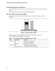
... Table 3 describes the LED states when the board is powered up and the 10/100 Ethernet LAN subsystem is selected 16 Intel Desktop Board D201GLY2 Product Guide LAN Subsystem Software For LAN software and drivers, refer to the D201GLY2 link on Intel's World Wide Web site at: http://support.intel.com/support/motherboards/desktop RJ-45 LAN Connector LEDs Two LEDs...
... Table 3 describes the LED states when the board is powered up and the 10/100 Ethernet LAN subsystem is selected 16 Intel Desktop Board D201GLY2 Product Guide LAN Subsystem Software For LAN software and drivers, refer to the D201GLY2 link on Intel's World Wide Web site at: http://support.intel.com/support/motherboards/desktop RJ-45 LAN Connector LEDs Two LEDs...
Product Guide
Page 17
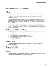
...8226; Up to two IDE devices (such as hard drives) • ATAPI-style devices (such as hard disks and optical drives inside the computer. Desktop Board Features Hi-Speed USB 2.0 Support NOTE Computer systems that fully support USB 2.0 transfer rates. USB 1.1 devices will function normally at USB 1.1 speeds.... meets the requirements for a full-speed USB device. This may be required to the cable. Expandability The Desktop Board supports one device per channel. BIOS The BIOS provides the Power-On Self-Test (POST), the BIOS Setup program, the PCI and IDE auto-configuration utilities, and the ...
...8226; Up to two IDE devices (such as hard drives) • ATAPI-style devices (such as hard disks and optical drives inside the computer. Desktop Board Features Hi-Speed USB 2.0 Support NOTE Computer systems that fully support USB 2.0 transfer rates. USB 1.1 devices will function normally at USB 1.1 speeds.... meets the requirements for a full-speed USB device. This may be required to the cable. Expandability The Desktop Board supports one device per channel. BIOS The BIOS provides the Power-On Self-Test (POST), the BIOS Setup program, the PCI and IDE auto-configuration utilities, and the ...
Product Guide
Page 18
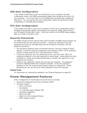
... user password to run the BIOS Setup program after installing an IDE device. If only the supervisor password is booted. Power Management Features Power management is set , you must enter either password to view and change all Setup options. If only the supervisor password... Clearing Passwords on whether the supervisor or user password was entered. • Setting a user password restricts who can boot the computer. Intel Desktop Board D201GLY2 Product Guide IDE Auto Configuration If you install an IDE device (such as a hard drive) in your computer. Setup options are set...
... user password to run the BIOS Setup program after installing an IDE device. If only the supervisor password is booted. Power Management Features Power management is set , you must enter either password to view and change all Setup options. If only the supervisor password... Clearing Passwords on whether the supervisor or user password was entered. • Setting a user password restricts who can boot the computer. Intel Desktop Board D201GLY2 Product Guide IDE Auto Configuration If you install an IDE device (such as a hard drive) in your computer. Setup options are set...
Product Guide
Page 19
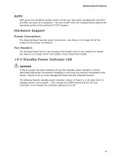
...computer appears to be off and the standby power indicator is standby power to the board. The use of a computer. Fan Headers The Desktop Board has a 3-pin processor fan header and a 3-pin chassis fan header. Desktop Board Features ACPI ACPI gives the operating system direct... control over the power management and Plug and Play functions of ACPI with the Desktop Board requires an operating system that provides full ACPI support. Hardware Support Power Connectors The Desktop Board has two power connectors. ...
...computer appears to be off and the standby power indicator is standby power to the board. The use of a computer. Fan Headers The Desktop Board has a 3-pin processor fan header and a 3-pin chassis fan header. Desktop Board Features ACPI ACPI gives the operating system direct... control over the power management and Plug and Play functions of ACPI with the Desktop Board requires an operating system that provides full ACPI support. Hardware Support Power Connectors The Desktop Board has two power connectors. ...
Product Guide
Page 20
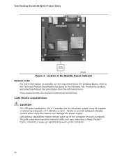
... the product, and selecting Product Documentation from the left-hand menu: http://support.intel.com/support/motherboards/desktop/ LAN Wake Capabilities CAUTION For LAN wake capabilities, the 5 V standby line for the power supply must be capable of the computer through a network. LAN wakeup capabilities enable remote wake-up the computer. 20 Intel Desktop Board D201GLY2 Product Guide Figure 4.
... the product, and selecting Product Documentation from the left-hand menu: http://support.intel.com/support/motherboards/desktop/ LAN Wake Capabilities CAUTION For LAN wake capabilities, the 5 V standby line for the power supply must be capable of the computer through a network. LAN wakeup capabilities enable remote wake-up the computer. 20 Intel Desktop Board D201GLY2 Product Guide Figure 4.
Product Guide
Page 23
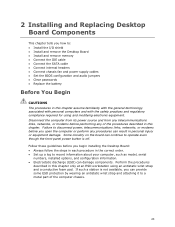
...8226; Install the I/O shield • Install and remove the Desktop Board • Install and remove memory • Connect the IDE cable • Connect the SATA cable • Connect internal headers • Connect chassis fan and power supply cables • Set the BIOS configuration and audio jumpers ... and a conductive foam pad. Failure to disconnect power, telecommunications links, networks, or modems before you open the computer or perform any of the computer chassis. 23 Follow these guidelines before you begin installing the Desktop Board: • Always follow the steps in each ...
...8226; Install the I/O shield • Install and remove the Desktop Board • Install and remove memory • Connect the IDE cable • Connect the SATA cable • Connect internal headers • Connect chassis fan and power supply cables • Set the BIOS configuration and audio jumpers ... and a conductive foam pad. Failure to disconnect power, telecommunications links, networks, or modems before you open the computer or perform any of the computer chassis. 23 Follow these guidelines before you begin installing the Desktop Board: • Always follow the steps in each ...

Product Guide
Page 24
To avoid overloading the power supply, make sure that the calculated total current loads of all the modules within the computer is less than the output current rating of each ..., be careful of the power supplies output circuits. If you do not follow these instructions and the instructions provided by chassis and module suppliers, you to refer computer servicing to Appendix B for safety and regulatory requirements. 24 Intel Desktop Board D201GLY2 Product Guide Installation Precautions When you install and test the Intel Desktop Board, observe all warnings and...
To avoid overloading the power supply, make sure that the calculated total current loads of all the modules within the computer is less than the output current rating of each ..., be careful of the power supplies output circuits. If you do not follow these instructions and the instructions provided by chassis and module suppliers, you to refer computer servicing to Appendix B for safety and regulatory requirements. 24 Intel Desktop Board D201GLY2 Product Guide Installation Precautions When you install and test the Intel Desktop Board, observe all warnings and...
Product Guide
Page 26
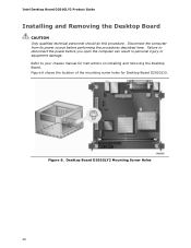
... before you open the computer can result in personal injury or equipment damage. Refer to disconnect the power before performing the procedures described here. Figure 6. Intel Desktop Board D201GLY2 Product Guide Installing and Removing the Desktop Board CAUTION Only qualified technical personnel should do this procedure. Figure 6 shows the location of the mounting screw holes for instructions...
... before you open the computer can result in personal injury or equipment damage. Refer to disconnect the power before performing the procedures described here. Figure 6. Intel Desktop Board D201GLY2 Product Guide Installing and Removing the Desktop Board CAUTION Only qualified technical personnel should do this procedure. Figure 6 shows the location of the mounting screw holes for instructions...
Product Guide
Page 28
.... 3. Position the DIMM above the socket. Replace the computer's cover and reconnect the AC power cord. 28 Remove the computer's cover and locate the DIMM socket (see Figure 8). 7. Installing a DIMM 4. Make sure the clips are pushed outward to the computer. ... its anti-static package. 6. When the DIMM is inserted, push down on page 23. 2. Figure 8. Turn off all peripheral devices connected to the open position. 5. Intel Desktop Board D201GLY2 Product Guide 1. Align the small notch at either end of the DIMM with the key in "Before You Begin" on the top edge of the...
.... 3. Position the DIMM above the socket. Replace the computer's cover and reconnect the AC power cord. 28 Remove the computer's cover and locate the DIMM socket (see Figure 8). 7. Installing a DIMM 4. Make sure the clips are pushed outward to the computer. ... its anti-static package. 6. When the DIMM is inserted, push down on page 23. 2. Figure 8. Turn off all peripheral devices connected to the open position. 5. Intel Desktop Board D201GLY2 Product Guide 1. Align the small notch at either end of the DIMM with the key in "Before You Begin" on the top edge of the...
Product Guide
Page 29
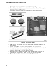
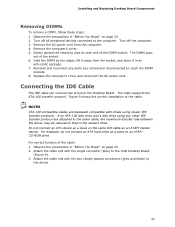
... of the cable. Hold the DIMM by the edges, lift it in an anti-static package. 7. Replace the computer's cover and reconnect the AC power cord. If an ATA-100 disk drive and a disk drive using slower IDE transfer protocols. Attach the cable end with the single connector (blue) ... page 23. 2. NOTES ATA-100 compatible cables are attached to the same cable, the maximum transfer rate between the drives may be reduced to the Intel Desktop Board (Figure 9). 3. Do not connect an ATA device as a slave on page 23. 2. Observe the precautions in "Before You Begin" on the same IDE cable...
... of the cable. Hold the DIMM by the edges, lift it in an anti-static package. 7. Replace the computer's cover and reconnect the AC power cord. If an ATA-100 disk drive and a disk drive using slower IDE transfer protocols. Attach the cable end with the single connector (blue) ... page 23. 2. NOTES ATA-100 compatible cables are attached to the same cable, the maximum transfer rate between the drives may be reduced to the Intel Desktop Board (Figure 9). 3. Do not connect an ATA device as a slave on page 23. 2. Observe the precautions in "Before You Begin" on the same IDE cable...
Product Guide
Page 33
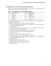
...the precautions in "Before You Begin" on page 23. 2. Install a jumper on pins 9-10 (rear L channel). 7. Installing and Replacing Desktop Board Components Installing a Front Panel Audio Solution Figure 11, A shows the location of the front panel audio header. Locate the front panel audio ...Install a correctly keyed and shielded front panel audio cable. 6. Turn off the computer and disconnect the AC power cord. 3. Turn off the computer and disconnect the AC power cord. 3. Turn off all peripheral devices connected to the computer. Replace the cover. 33 Remove the front ...
...the precautions in "Before You Begin" on page 23. 2. Install a jumper on pins 9-10 (rear L channel). 7. Installing and Replacing Desktop Board Components Installing a Front Panel Audio Solution Figure 11, A shows the location of the front panel audio header. Locate the front panel audio ...Install a correctly keyed and shielded front panel audio cable. 6. Turn off the computer and disconnect the AC power cord. 3. Turn off the computer and disconnect the AC power cord. 3. Turn off all peripheral devices connected to the computer. Replace the cover. 33 Remove the front ...
Product Guide
Page 34
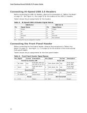
... Pin Signal Name 2 Power 4 D- 6 D+ 8 Ground 10 No connect Note: USB ports may be assigned as needed. Connecting the Front Panel Header Before connecting the front panel header, observe the precautions in "Before You Begin" on page 32 for the location of the multi-colored front panel header. Intel Desktop Board D201GLY2 Product Guide Connecting Hi...
... Pin Signal Name 2 Power 4 D- 6 D+ 8 Ground 10 No connect Note: USB ports may be assigned as needed. Connecting the Front Panel Header Before connecting the front panel header, observe the precautions in "Before You Begin" on page 32 for the location of the multi-colored front panel header. Intel Desktop Board D201GLY2 Product Guide Connecting Hi...
Product Guide
Page 36
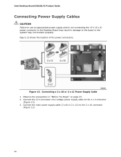
... system may result in "Before You Begin" on page 23. 2. Intel Desktop Board D201GLY2 Product Guide Connecting Power Supply Cables CAUTION Failure to use an appropriate power supply and/or not connecting the 12 V (2 x 2) power connector to the Desktop Board may not function properly. Connect the 12 V processor core voltage power supply cable to the 2 x 10 connector (Figure 13). 36
... system may result in "Before You Begin" on page 23. 2. Intel Desktop Board D201GLY2 Product Guide Connecting Power Supply Cables CAUTION Failure to use an appropriate power supply and/or not connecting the 12 V (2 x 2) power connector to the Desktop Board may not function properly. Connect the 12 V processor core voltage power supply cable to the 2 x 10 connector (Figure 13). 36

