Product Guide
Page 2
... from digital apparatus set out in the United States and other intellectual property right. Copyright © 2007, Intel Corporation. Desktop Board D201GLY2 may contain design defects or errors known as errata which have an ordering number and are designed to provide reasonable... others. Revision History Revision Revision History -001 First release of the Intel® Desktop Board D201GLY2 Product Guide Date September 2007 If an FCC declaration of conformity marking is present on the board, the following statement applies: FCC Declaration of Conformity This device complies with...
... from digital apparatus set out in the United States and other intellectual property right. Copyright © 2007, Intel Corporation. Desktop Board D201GLY2 may contain design defects or errors known as errata which have an ordering number and are designed to provide reasonable... others. Revision History Revision Revision History -001 First release of the Intel® Desktop Board D201GLY2 Product Guide Date September 2007 If an FCC declaration of conformity marking is present on the board, the following statement applies: FCC Declaration of Conformity This device complies with...
Product Guide
Page 3
..., and similar locations. The suitability of this Product Guide are evaluated as follows: 1 Desktop Board Features: a summary of data. iii Intended Uses All Intel® Desktop Boards are arranged as Information Technology Equipment (I.T.E.) for use in personal computers (PC) for Intel® Desktop Board D201GLY2. Intended Audience The Product Guide is not intended for technically qualified personnel. It is...
..., and similar locations. The suitability of this Product Guide are evaluated as follows: 1 Desktop Board Features: a summary of data. iii Intended Uses All Intel® Desktop Boards are arranged as Information Technology Equipment (I.T.E.) for use in personal computers (PC) for Intel® Desktop Board D201GLY2. Intended Audience The Product Guide is not intended for technically qualified personnel. It is...
Product Guide
Page 4
... bits) MHz Megahertz (one million hertz) Box Contents • Intel Desktop Board • I/O shield • One ATA-66/100 cable • One Serial ATA (SATA) cable • Quick Reference Guide • Configuration and safety labels • Intel® Express Installer driver CD-ROM iv Intel Desktop Board D201GLY2 Product Guide Terminology The table below gives descriptions to some...
... bits) MHz Megahertz (one million hertz) Box Contents • Intel Desktop Board • I/O shield • One ATA-66/100 cable • One Serial ATA (SATA) cable • Quick Reference Guide • Configuration and safety labels • Intel® Express Installer driver CD-ROM iv Intel Desktop Board D201GLY2 Product Guide Terminology The table below gives descriptions to some...
Product Guide
Page 5
...21 Wake from PS/2 Keyboard/Mouse 21 PME# Wakeup Support 21 Battery ...21 Real-Time Clock 21 2 Installing and Replacing Desktop Board Components Before You Begin 23 Installation Precautions 24 Prevent Power Supply Overload 24 Observe Safety and Regulatory Requirements 24 Installing the I/O ...Shield 25 Installing and Removing the Desktop Board 26 Installing and Removing Memory 27 Installing DIMMs 27 Removing DIMMs 29 Connecting the IDE Cable 29 Connecting the Serial ATA ...
...21 Wake from PS/2 Keyboard/Mouse 21 PME# Wakeup Support 21 Battery ...21 Real-Time Clock 21 2 Installing and Replacing Desktop Board Components Before You Begin 23 Installation Precautions 24 Prevent Power Supply Overload 24 Observe Safety and Regulatory Requirements 24 Installing the I/O ...Shield 25 Installing and Removing the Desktop Board 26 Installing and Removing Memory 27 Installing DIMMs 27 Removing DIMMs 29 Connecting the IDE Cable 29 Connecting the Serial ATA ...
Product Guide
Page 6
Intel Desktop Board D201GLY2 Product Guide Connecting the Front Panel Header 34 Connecting the Chassis Fan 35 Connecting Supply Power Cables 36 Setting the Desktop Board Jumpers 37 Front Panel Audio Header/Jumper Block 37 BIOS Configuration Jumper 38 Clearing Passwords 39 Replacing the Battery 40 3 Updating the BIOS Updating the BIOS with the Intel...Declaration of Conformity Statement 50 Product Ecology Statements 51 Recycling Considerations 51 Lead-free 2LI/Pb-free 2LI Board 54 Restriction of Hazardous Substances (RoHS 55 European Union RoHS 55 China RoHS 55 EMC Regulations 58 ...
Intel Desktop Board D201GLY2 Product Guide Connecting the Front Panel Header 34 Connecting the Chassis Fan 35 Connecting Supply Power Cables 36 Setting the Desktop Board Jumpers 37 Front Panel Audio Header/Jumper Block 37 BIOS Configuration Jumper 38 Clearing Passwords 39 Replacing the Battery 40 3 Updating the BIOS Updating the BIOS with the Intel...Declaration of Conformity Statement 50 Product Ecology Statements 51 Recycling Considerations 51 Lead-free 2LI/Pb-free 2LI Board 54 Restriction of Hazardous Substances (RoHS 55 European Union RoHS 55 China RoHS 55 EMC Regulations 58 ...
Product Guide
Page 7
... Front Panel Audio Header/Jumper Block 38 8. BIOS Error Messages 47 11. Product Certification Markings 60 vii Desktop Board D201GLY2 Mounting Screw Holes 26 7. Removing the Battery 44 16. RJ-45 10/100 Ethernet LAN Connector LEDs...4. Lead-Free Second Level Interconnect Marks 55 13. Connecting the IDE Cable 30 10. Desktop Board Jumpers 37 15. Desktop Boards D201GLY2 Components 12 3. China RoHS Environmentally Friendly Use Period Mark 56 14. Location of the ...Audio Connectors 15 3. Front Panel Audio Header Signal Names 33 5. Intel Desktop Board D201GLY2 Components 11 2.
... Front Panel Audio Header/Jumper Block 38 8. BIOS Error Messages 47 11. Product Certification Markings 60 vii Desktop Board D201GLY2 Mounting Screw Holes 26 7. Removing the Battery 44 16. RJ-45 10/100 Ethernet LAN Connector LEDs...4. Lead-Free Second Level Interconnect Marks 55 13. Connecting the IDE Cable 30 10. Desktop Board Jumpers 37 15. Desktop Boards D201GLY2 Components 12 3. China RoHS Environmentally Friendly Use Period Mark 56 14. Location of the ...Audio Connectors 15 3. Front Panel Audio Header Signal Names 33 5. Intel Desktop Board D201GLY2 Components 11 2.
Product Guide
Page 9
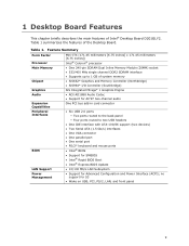
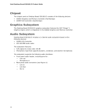
...; One 240-pin SDRAM Dual Inline Memory Module (DIMM) socket • 533/400 MHz single channel DDR2 SDRAM interface • Supports up to 1 GB of Intel® Desktop Board D201GLY2. 1 Desktop Board Features This chapter briefly describes the main features of system memory Chipset • SiS662* Graphics and Memory Controller (Northbridge) • SiS964* I/O Controller (Southbridge) Graphics...
...; One 240-pin SDRAM Dual Inline Memory Module (DIMM) socket • 533/400 MHz single channel DDR2 SDRAM interface • Supports up to 1 GB of Intel® Desktop Board D201GLY2. 1 Desktop Board Features This chapter briefly describes the main features of system memory Chipset • SiS662* Graphics and Memory Controller (Northbridge) • SiS964* I/O Controller (Southbridge) Graphics...
Product Guide
Page 10
Intel Desktop Board D201GLY2 Product Guide Related Links: For more information about Desktop Board D201GLY2, including the Technical Product Specification (TPS), BIOS updates, and device drivers, go to: http://support.intel.com/support/motherboards/desktop/ Supported Operating Systems The Desktop Board supports the following operating systems: • Microsoft Windows Vista* Starter Edition • Microsoft Windows* XP Professional • Microsoft Windows XP Home • Microsoft Windows XP Starter Edition 10
Intel Desktop Board D201GLY2 Product Guide Related Links: For more information about Desktop Board D201GLY2, including the Technical Product Specification (TPS), BIOS updates, and device drivers, go to: http://support.intel.com/support/motherboards/desktop/ Supported Operating Systems The Desktop Board supports the following operating systems: • Microsoft Windows Vista* Starter Edition • Microsoft Windows* XP Professional • Microsoft Windows XP Home • Microsoft Windows XP Starter Edition 10
Product Guide
Page 11
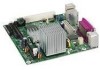
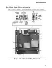
Intel Desktop Board D201GLY2 Components 11 Desktop Board Features Desktop Board Components Figure 1 shows the location of the major components on Desktop Board D201GLY2. Figure 1.
Intel Desktop Board D201GLY2 Components 11 Desktop Board Features Desktop Board Components Figure 1 shows the location of the major components on Desktop Board D201GLY2. Figure 1.
Product Guide
Page 12
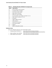
Desktop Boards D201GLY2 Components Label A B C D E F G H I J K L M N Description PCI bus add-in card connector Hi-speed USB 2.0 headers Front panel audio header Back panel connectors Rear fan ...jumper Related Links: Go to the following links for more information about: • Desktop Board D201GLY2 • Audio software and utilities • LAN software and drivers http://www.intel.com/design/motherbd http://support.intel.com/support/motherboards/desktop http://www.intel.com/design/motherbd http://www.intel.com/design/motherbd 12 Intel Desktop Board D201GLY2 Product Guide Table 2.
Desktop Boards D201GLY2 Components Label A B C D E F G H I J K L M N Description PCI bus add-in card connector Hi-speed USB 2.0 headers Front panel audio header Back panel connectors Rear fan ...jumper Related Links: Go to the following links for more information about: • Desktop Board D201GLY2 • Audio software and utilities • LAN software and drivers http://www.intel.com/design/motherbd http://support.intel.com/support/motherboards/desktop http://www.intel.com/design/motherbd http://www.intel.com/design/motherbd 12 Intel Desktop Board D201GLY2 Product Guide Table 2.
Product Guide
Page 13
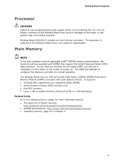
...-ECC memory • Up to 1 GB of tested memory, http://support.intel.com/support/motherboards/desktop/ • SDRAM specifications, http://www.intel.com/technology/memory/ • Installing memory, page 27 in damage to the board, or the system may not function properly. Desktop Board D201GLY2 includes an Intel Celeron processor. Main Memory NOTE To be fully compliant with all...
...-ECC memory • Up to 1 GB of tested memory, http://support.intel.com/support/motherboards/desktop/ • SDRAM specifications, http://www.intel.com/technology/memory/ • Installing memory, page 27 in damage to the board, or the system may not function properly. Desktop Board D201GLY2 includes an Intel Celeron processor. Main Memory NOTE To be fully compliant with all...
Product Guide
Page 14
Intel Desktop Board D201GLY2 Product Guide Chipset The chipset used on the following audio interfaces: • Front panel audio header, including pins for: ― Line out ― Microphone in the SiS662 Graphics and Memory Controller. Audio Subsystem Desktop Board D201GLY2 includes a 2-channel audio subsystem based on Desktop Board D201GLY2... The subsystem supports the following devices: • SiS964 I /O Controller (Southbridge) Graphics Subsystem The Desktop Board D201GLY2 graphics subsystem features the SiS* Mirage* 1 Graphics Engine which is integrated in • Back panel...
Intel Desktop Board D201GLY2 Product Guide Chipset The chipset used on the following audio interfaces: • Front panel audio header, including pins for: ― Line out ― Microphone in the SiS662 Graphics and Memory Controller. Audio Subsystem Desktop Board D201GLY2 includes a 2-channel audio subsystem based on Desktop Board D201GLY2... The subsystem supports the following devices: • SiS964 I /O Controller (Southbridge) Graphics Subsystem The Desktop Board D201GLY2 graphics subsystem features the SiS* Mirage* 1 Graphics Engine which is integrated in • Back panel...
Product Guide
Page 15
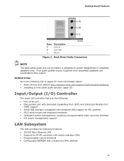
... if passive (non-amplified) speakers are connected to the following link or pages for more information about: • Audio drivers and utilities http://support.intel.com/support/motherboards/desktop/ • Installing a front panel audio solution (page 33) Input/Output (I/O) Controller The super I/O controller features the following: • One serial port &#...this output. Back Panel Audio Connectors NOTE The back panel audio line out connector is designed to power headphones or amplified speakers only. Desktop Board Features Item A B C Description Line In Line Out Mic In Figure 2.
... if passive (non-amplified) speakers are connected to the following link or pages for more information about: • Audio drivers and utilities http://support.intel.com/support/motherboards/desktop/ • Installing a front panel audio solution (page 33) Input/Output (I/O) Controller The super I/O controller features the following: • One serial port &#...this output. Back Panel Audio Connectors NOTE The back panel audio line out connector is designed to power headphones or amplified speakers only. Desktop Board Features Item A B C Description Line In Line Out Mic In Figure 2.
Product Guide
Page 16
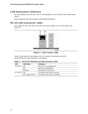
... occurring 10 Mbits/s data rate is selected 100 Mbits/s data rate is operating. Intel Desktop Board D201GLY2 Product Guide LAN Subsystem Software For LAN software and drivers, refer to the D201GLY2 link on Intel's World Wide Web site at: http://support.intel.com/support/motherboards/desktop RJ-45 LAN Connector LEDs Two LEDs are built into the RJ-45...
... occurring 10 Mbits/s data rate is selected 100 Mbits/s data rate is operating. Intel Desktop Board D201GLY2 Product Guide LAN Subsystem Software For LAN software and drivers, refer to the D201GLY2 link on Intel's World Wide Web site at: http://support.intel.com/support/motherboards/desktop RJ-45 LAN Connector LEDs Two LEDs are built into the RJ-45...
Product Guide
Page 17
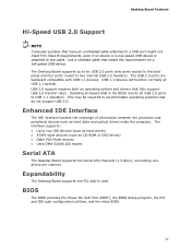
... 2.0 support requires both an operating system and drivers that meets the requirements for a full-speed USB device. Disabling Hi-Speed USB in card. The Desktop Board supports up to six USB 2.0 ports (two ports routed to the back panel and four ports routed to USB 1.1 operation. BIOS The BIOS provides...peripheral devices such as CD-ROM or DVD drives) • Older PIO Mode devices • Ultra DMA-33/66/100 modes Serial ATA The Desktop Board supports two Serial ATA channels (1.5 Gb/s), connecting one PCI add-in the BIOS reverts all USB 2.0 ports to two internal USB 2.0 headers). The...
... 2.0 support requires both an operating system and drivers that meets the requirements for a full-speed USB device. Disabling Hi-Speed USB in card. The Desktop Board supports up to six USB 2.0 ports (two ports routed to the back panel and four ports routed to USB 1.1 operation. BIOS The BIOS provides...peripheral devices such as CD-ROM or DVD drives) • Older PIO Mode devices • Ultra DMA-33/66/100 modes Serial ATA The Desktop Board supports two Serial ATA channels (1.5 Gb/s), connecting one PCI add-in the BIOS reverts all USB 2.0 ports to two internal USB 2.0 headers). The...
Product Guide
Page 18
... and for a password. If only the supervisor password is implemented at the password prompt of Setup gives the user restricted access to boot the computer. Intel Desktop Board D201GLY2 Product Guide IDE Auto Configuration If you install an IDE device (such as a hard drive) in your computer, the autoconfiguration utility in the BIOS automatically...
... and for a password. If only the supervisor password is implemented at the password prompt of Setup gives the user restricted access to boot the computer. Intel Desktop Board D201GLY2 Product Guide IDE Auto Configuration If you install an IDE device (such as a hard drive) in your computer, the autoconfiguration utility in the BIOS automatically...
Product Guide
Page 19
... LED CAUTION If the AC power has been switched off . 19 See Figure 12 on page 36 for the location of the power connectors. The Desktop Board's standby power indicator, shown in Figure 4, is lit when there is still lit, disconnect the power cord before installing or removing any attached devices... ACPI ACPI gives the operating system direct control over the power management and Plug and Play functions of ACPI with the Desktop Board requires an operating system that provides full ACPI support. This includes the DIMM socket and the PCI bus connector, even though the computer appears to ...
... LED CAUTION If the AC power has been switched off . 19 See Figure 12 on page 36 for the location of the power connectors. The Desktop Board's standby power indicator, shown in Figure 4, is lit when there is still lit, disconnect the power cord before installing or removing any attached devices... ACPI ACPI gives the operating system direct control over the power management and Plug and Play functions of ACPI with the Desktop Board requires an operating system that provides full ACPI support. This includes the DIMM socket and the PCI bus connector, even though the computer appears to ...
Product Guide
Page 20
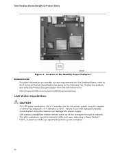
... capabilities enable remote wake-up the computer. 20 Intel Desktop Board D201GLY2 Product Guide Figure 4. Location of the Standby Power Indicator Related Links: For more information on standby current requirements for the Desktop Board, refer to the Technical Product Specification by going to...current. Failure to the following link, finding the product, and selecting Product Documentation from the left-hand menu: http://support.intel.com/support/motherboards/desktop/ LAN Wake Capabilities CAUTION For LAN wake capabilities, the 5 V standby line for the power supply must be capable of...
... capabilities enable remote wake-up the computer. 20 Intel Desktop Board D201GLY2 Product Guide Figure 4. Location of the Standby Power Indicator Related Links: For more information on standby current requirements for the Desktop Board, refer to the Technical Product Specification by going to...current. Failure to the following link, finding the product, and selecting Product Documentation from the left-hand menu: http://support.intel.com/support/motherboards/desktop/ LAN Wake Capabilities CAUTION For LAN wake capabilities, the 5 V standby line for the power supply must be capable of...
Product Guide
Page 21
... and the clock current when the computer is turned off . 21 Real-Time Clock The Desktop Board has a time-of a USB peripheral that supports wake from USB. Battery A battery on the PCI bus is turned off . Desktop Board Features Wake from USB NOTE Wake from USB requires the use of -day clock and 100... activity wakes the computer from an ACPI S1 state. The battery on how to replace the battery. Go to page 40 for instructions on the Desktop Board keeps the clock current when the computer is asserted, the computer wakes from an ACPI S1 or S5 state.
... and the clock current when the computer is turned off . 21 Real-Time Clock The Desktop Board has a time-of a USB peripheral that supports wake from USB. Battery A battery on the PCI bus is turned off . Desktop Board Features Wake from USB NOTE Wake from USB requires the use of -day clock and 100... activity wakes the computer from an ACPI S1 state. The battery on how to replace the battery. Go to page 40 for instructions on the Desktop Board keeps the clock current when the computer is asserted, the computer wakes from an ACPI S1 or S5 state.
Product Guide
Page 23
... This chapter tells you begin installing the Desktop Board: • Always follow the steps in each procedure in the correct ... options, and configuration information. • Electrostatic discharge (ESD) can damage components. Some circuitry on the board can continue to operate even though the front panel power button is not available, you open the computer or... an antistatic wrist strap and attaching it to : • Install the I/O shield • Install and remove the Desktop Board • Install and remove memory • Connect the IDE cable • Connect the SATA cable • Connect...
... This chapter tells you begin installing the Desktop Board: • Always follow the steps in each procedure in the correct ... options, and configuration information. • Electrostatic discharge (ESD) can damage components. Some circuitry on the board can continue to operate even though the front panel power button is not available, you open the computer or... an antistatic wrist strap and attaching it to : • Install the I/O shield • Install and remove the Desktop Board • Install and remove memory • Connect the IDE cable • Connect the SATA cable • Connect...


