Product Guide
Page 5
Contents 1 Desktop Board Features Supported Operating Systems 10 Desktop Board Components 11 Processor ...13 Main Memory...13 Chipset...14 Graphics Subsystem 14 Audio Subsystem 14 Input/Output (I/O) Controller 15 LAN Subsystem 15 LAN Subsystem Software 16 ...Precautions 24 Prevent Power Supply Overload 24 Observe Safety and Regulatory Requirements 24 Installing the I/O Shield 25 Installing and Removing the Desktop Board 26 Installing and Removing Memory 27 Installing DIMMs 27 Removing DIMMs 29 Connecting the IDE Cable 29 Connecting the Serial ATA (SATA) Cable 31 Connecting ...
Contents 1 Desktop Board Features Supported Operating Systems 10 Desktop Board Components 11 Processor ...13 Main Memory...13 Chipset...14 Graphics Subsystem 14 Audio Subsystem 14 Input/Output (I/O) Controller 15 LAN Subsystem 15 LAN Subsystem Software 16 ...Precautions 24 Prevent Power Supply Overload 24 Observe Safety and Regulatory Requirements 24 Installing the I/O Shield 25 Installing and Removing the Desktop Board 26 Installing and Removing Memory 27 Installing DIMMs 27 Removing DIMMs 29 Connecting the IDE Cable 29 Connecting the Serial ATA (SATA) Cable 31 Connecting ...
Product Guide
Page 6
Intel Desktop Board D201GLY2 Product Guide Connecting the Front Panel Header 34 Connecting the Chassis Fan 35 Connecting Supply Power Cables 36 Setting the Desktop Board Jumpers 37 Front Panel Audio Header/Jumper Block 37 BIOS Configuration Jumper 38 Clearing Passwords 39 Replacing the Battery 40 3 Updating the BIOS Updating the BIOS with the Intel® Express BIOS...
Intel Desktop Board D201GLY2 Product Guide Connecting the Front Panel Header 34 Connecting the Chassis Fan 35 Connecting Supply Power Cables 36 Setting the Desktop Board Jumpers 37 Front Panel Audio Header/Jumper Block 37 BIOS Configuration Jumper 38 Clearing Passwords 39 Replacing the Battery 40 3 Updating the BIOS Updating the BIOS with the Intel® Express BIOS...
Product Guide
Page 9
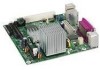
...millimeters [6.75 inches]) Intel® Celeron® processor Main Memory • One 240-pin SDRAM Dual Inline Memory Module (DIMM) socket • 533/400 MHz single channel DDR2 SDRAM interface • Supports up to 1 GB of system memory Chipset • SiS662* Graphics and Memory Controller (Northbridge) ... PS/2, LAN, and front panel 9 no support for Advanced Configuration and Power Interface (ACPI); 1 Desktop Board Features This chapter briefly describes the main features of the Desktop Board. Table 1. Table 1 summarizes the features of Intel® Desktop Board D201GLY2.
...millimeters [6.75 inches]) Intel® Celeron® processor Main Memory • One 240-pin SDRAM Dual Inline Memory Module (DIMM) socket • 533/400 MHz single channel DDR2 SDRAM interface • Supports up to 1 GB of system memory Chipset • SiS662* Graphics and Memory Controller (Northbridge) ... PS/2, LAN, and front panel 9 no support for Advanced Configuration and Power Interface (ACPI); 1 Desktop Board Features This chapter briefly describes the main features of the Desktop Board. Table 1. Table 1 summarizes the features of Intel® Desktop Board D201GLY2.
Product Guide
Page 13
... of tested memory, http://support.intel.com/support/motherboards/desktop/ • SDRAM specifications, http://www.intel.com/technology/memory/ • Installing memory, page 27 in damage to the board, or the system may result in Chapter 2 13 The BIOS will see a notification to the following links or pages for normal operation. The processor is not customer upgradeable. Desktop Board Features...
... of tested memory, http://support.intel.com/support/motherboards/desktop/ • SDRAM specifications, http://www.intel.com/technology/memory/ • Installing memory, page 27 in damage to the board, or the system may result in Chapter 2 13 The BIOS will see a notification to the following links or pages for normal operation. The processor is not customer upgradeable. Desktop Board Features...
Product Guide
Page 14
Intel Desktop Board D201GLY2 Product Guide Chipset The chipset used on the following audio interfaces: • Front panel audio header, including pins for: ― Line out ― Microphone in the SiS662 Graphics and Memory Controller. Audio Subsystem Desktop Board D201GLY2 includes a 2-channel audio subsystem based on Desktop Board D201GLY2 consists of the following devices: • SiS662 Graphics and Memory Controller (Northbridge) • SiS964...
Intel Desktop Board D201GLY2 Product Guide Chipset The chipset used on the following audio interfaces: • Front panel audio header, including pins for: ― Line out ― Microphone in the SiS662 Graphics and Memory Controller. Audio Subsystem Desktop Board D201GLY2 includes a 2-channel audio subsystem based on Desktop Board D201GLY2 consists of the following devices: • SiS662 Graphics and Memory Controller (Northbridge) • SiS964...
Product Guide
Page 23
...in this chapter only at an ESD workstation using and modifying electronic equipment. Follow these guidelines before you begin installing the Desktop Board: • Always follow the steps in each procedure in personal injury or equipment damage. Failure to disconnect power, ...• Electrostatic discharge (ESD) can damage components. 2 Installing and Replacing Desktop Board Components This chapter tells you how to: • Install the I/O shield • Install and remove the Desktop Board • Install and remove memory • Connect the IDE cable • Connect the SATA cable •...
...in this chapter only at an ESD workstation using and modifying electronic equipment. Follow these guidelines before you begin installing the Desktop Board: • Always follow the steps in each procedure in personal injury or equipment damage. Failure to disconnect power, ...• Electrostatic discharge (ESD) can damage components. 2 Installing and Replacing Desktop Board Components This chapter tells you how to: • Install the I/O shield • Install and remove the Desktop Board • Install and remove memory • Connect the IDE cable • Connect the SATA cable •...
Product Guide
Page 27
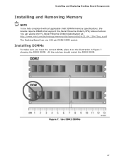
... the correct DIMM, place it on the illustration in Figure 7 showing the DDR2 DIMM. Installing and Replacing Desktop Board Components Installing and Removing Memory NOTE To be fully compliant with all applicable Intel SDRAM memory specifications, the boards require DIMMs that support the Serial Presence Detect (SPD) data structure. All the notches should match the DDR2...
... the correct DIMM, place it on the illustration in Figure 7 showing the DDR2 DIMM. Installing and Replacing Desktop Board Components Installing and Removing Memory NOTE To be fully compliant with all applicable Intel SDRAM memory specifications, the boards require DIMMs that support the Serial Presence Detect (SPD) data structure. All the notches should match the DDR2...
Product Guide
Page 40
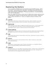
... usagées doivent être recyclées dans la mesure du possible. When the computer is plugged in accordance with an incorrect type. Intel Desktop Board D201GLY2 Product Guide Replacing the Battery A coin-cell battery (CR2032) powers the real-time clock and CMOS...
... usagées doivent être recyclées dans la mesure du possible. When the computer is plugged in accordance with an incorrect type. Intel Desktop Board D201GLY2 Product Guide Replacing the Battery A coin-cell battery (CR2032) powers the real-time clock and CMOS...
Product Guide
Page 45
...the Iflash BIOS update file. Go to the D201GLY2 page, click "[view] Latest BIOS updates," and select the Express BIOS Update utility file. 3. This is a compressed file that combines the functionality of the Intel® Flash Memory Update Utility and the ease of Windows-based ... Update utility: 1. The Iflash BIOS update file contains: • New BIOS file • Intel Flash Memory Update Utility 45 Navigate to the Intel World Wide Web site: http://support.intel.com/support/motherboards/desktop/ 2. This runs the update program. 6. Download the file to your hard drive where it ...
...the Iflash BIOS update file. Go to the D201GLY2 page, click "[view] Latest BIOS updates," and select the Express BIOS Update utility file. 3. This is a compressed file that combines the functionality of the Intel® Flash Memory Update Utility and the ease of Windows-based ... Update utility: 1. The Iflash BIOS update file contains: • New BIOS file • Intel Flash Memory Update Utility 45 Navigate to the Intel World Wide Web site: http://support.intel.com/support/motherboards/desktop/ 2. This runs the update program. 6. Download the file to your hard drive where it ...
Product Guide
Page 46
..., the BIOS could be extracted locally to your computer supplier or by navigating to the Desktop Board D201GLY2 page on the Intel World Wide Web site at: http://support.intel.com/support/motherboards/desktop Navigate to a bootable USB flash drive or other bootable USB media. Uncompress the BIOS update...BIOS update files can be damaged. For more information about recovering the BIOS for desktop board D201GLY2, go to the USB device. 3. Updating the BIOS with the Iflash Memory Update Utility With the Iflash Memory update utility you to: • Update the BIOS • Update the language ...
..., the BIOS could be extracted locally to your computer supplier or by navigating to the Desktop Board D201GLY2 page on the Intel World Wide Web site at: http://support.intel.com/support/motherboards/desktop Navigate to a bootable USB flash drive or other bootable USB media. Uncompress the BIOS update...BIOS update files can be damaged. For more information about recovering the BIOS for desktop board D201GLY2, go to the USB device. 3. Updating the BIOS with the Iflash Memory Update Utility With the Iflash Memory update utility you to: • Update the BIOS • Update the language ...
Product Guide
Page 47
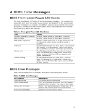
...powered off Thermal warning On-off (0.5 second each ) two times, then 3.0 second pause (off) between on-off blink pattern; Memory size has decreased since the last boot. Front-panel Power LED Blink Codes Type Processor initialization complete POST complete BIOS update in progress Pattern...off blink pattern; repeat entire pattern (three on -off blinks and 3-second pause) until BIOS update is incorrect. CMOS Checksum Bad Memory Size Decreased No Boot Device Available The CMOS checksum is complete. BIOS Error Messages Error Message CMOS Battery Low Explanation The battery may ...
...powered off Thermal warning On-off (0.5 second each ) two times, then 3.0 second pause (off) between on-off blink pattern; Memory size has decreased since the last boot. Front-panel Power LED Blink Codes Type Processor initialization complete POST complete BIOS update in progress Pattern...off blink pattern; repeat entire pattern (three on -off blinks and 3-second pause) until BIOS update is incorrect. CMOS Checksum Bad Memory Size Decreased No Boot Device Available The CMOS checksum is complete. BIOS Error Messages Error Message CMOS Battery Low Explanation The battery may ...


