Product Guide
Page 5
Contents 1 Desktop Board Features Supported Operating Systems 10 Desktop Board Components 11 Processor ...13 Main Memory ...13 Chipset ...14 Graphics Subsystem 14 Audio Subsystem 14 Input/Output (I/O) Controller 15 LAN Subsystem 15 LAN Subsystem Software 16... 22 Prevent Power Supply Overload 22 Observe Safety and Regulatory Requirements 22 Installing the I/O Shield 23 Installing and Removing the Desktop Board 24 Installing and Removing Memory 25 Installing DIMMs 25 Removing DIMMs 27 Connecting the IDE Cable 27 Connecting Internal Headers 29 Installing a Front Panel Audio ...
Contents 1 Desktop Board Features Supported Operating Systems 10 Desktop Board Components 11 Processor ...13 Main Memory ...13 Chipset ...14 Graphics Subsystem 14 Audio Subsystem 14 Input/Output (I/O) Controller 15 LAN Subsystem 15 LAN Subsystem Software 16... 22 Prevent Power Supply Overload 22 Observe Safety and Regulatory Requirements 22 Installing the I/O Shield 23 Installing and Removing the Desktop Board 24 Installing and Removing Memory 25 Installing DIMMs 25 Removing DIMMs 27 Connecting the IDE Cable 27 Connecting Internal Headers 29 Installing a Front Panel Audio ...
Product Guide
Page 6
Intel Desktop Board D201GLY Product Guide Setting the Desktop Board Jumpers 34 Front Panel Audio Header/Jumper Block 34 BIOS Configuration Jumper 35 Clearing Passwords 36 Replacing the Battery 37 3 Updating the BIOS Updating the BIOS with the Iflash Memory Update Utility 43 Obtaining the BIOS Update File 43 Updating the BIOS with the Iflash Memory Update Utility 43...
Intel Desktop Board D201GLY Product Guide Setting the Desktop Board Jumpers 34 Front Panel Audio Header/Jumper Block 34 BIOS Configuration Jumper 35 Clearing Passwords 36 Replacing the Battery 37 3 Updating the BIOS Updating the BIOS with the Iflash Memory Update Utility 43 Obtaining the BIOS Update File 43 Updating the BIOS with the Iflash Memory Update Utility 43...
Product Guide
Page 9
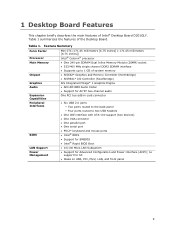
...Factor Processor Mini-ITX (171.45 millimeters [6.75 inches] x 171.45 millimeters [6.75 inches]) Intel® Celeron® processor Main Memory • One 240-pin SDRAM Dual Inline Memory Module (DIMM) socket • 533/400 MHz single channel DDR2 SDRAM interface • Supports ...SMBIOS • Intel® Rapid BIOS Boot LAN Support • 10/100 Mb/s LAN Subsystem Power Management • Support for S3 • Wake on USB, PCI, PS/2, LAN, and front panel 9 Table 1. Table 1 summarizes the features of Intel® Desktop Board D201GLY. 1 Desktop Board Features This chapter ...
...Factor Processor Mini-ITX (171.45 millimeters [6.75 inches] x 171.45 millimeters [6.75 inches]) Intel® Celeron® processor Main Memory • One 240-pin SDRAM Dual Inline Memory Module (DIMM) socket • 533/400 MHz single channel DDR2 SDRAM interface • Supports ...SMBIOS • Intel® Rapid BIOS Boot LAN Support • 10/100 Mb/s LAN Subsystem Power Management • Support for S3 • Wake on USB, PCI, PS/2, LAN, and front panel 9 Table 1. Table 1 summarizes the features of Intel® Desktop Board D201GLY. 1 Desktop Board Features This chapter ...
Product Guide
Page 13
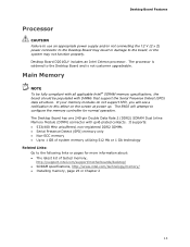
... information about: • The latest list of tested memory, http://support.intel.com/support/motherboards/desktop/ • SDRAM specifications, http://www.intel.com/technology/memory/ • Installing memory, page 25 in damage to the Desktop Board and is soldered to the board, or the system may not function properly. If your memory modules do not support SPD, you will attempt to...
... information about: • The latest list of tested memory, http://support.intel.com/support/motherboards/desktop/ • SDRAM specifications, http://www.intel.com/technology/memory/ • Installing memory, page 25 in damage to the Desktop Board and is soldered to the board, or the system may not function properly. If your memory modules do not support SPD, you will attempt to...
Product Guide
Page 14
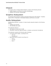
... of the following audio interfaces: • Front panel audio header, including pins for: ― Line out ― Microphone in the SiS662 Graphics and Memory Controller. Intel Desktop Board D201GLY Product Guide Chipset The chipset used on the following devices: • SiS964L I/O Controller • ADI AD1888 audio codec The subsystem features: • S/N (signal-to-noise) ...
... of the following audio interfaces: • Front panel audio header, including pins for: ― Line out ― Microphone in the SiS662 Graphics and Memory Controller. Intel Desktop Board D201GLY Product Guide Chipset The chipset used on the following devices: • SiS964L I/O Controller • ADI AD1888 audio codec The subsystem features: • S/N (signal-to-noise) ...
Product Guide
Page 19
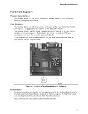
... 32 for the location of the chassis fan header. Fan Headers The Desktop Board has a 3-pin processor fan header and a 3-pin chassis fan header. Location of the power connectors. This includes the memory module and PCI bus connector, even when the computer appears to the ...power to the following link, finding the product, and selecting Product Documentation from the left-hand menu: http://support.intel.com/support/motherboards/desktop/ 19 Figure 4. Desktop Board Features Hardware Support Power Connectors The Desktop Board has two power connectors. See Figure 11 on page 33 for the...
... 32 for the location of the chassis fan header. Fan Headers The Desktop Board has a 3-pin processor fan header and a 3-pin chassis fan header. Location of the power connectors. This includes the memory module and PCI bus connector, even when the computer appears to the ...power to the following link, finding the product, and selecting Product Documentation from the left-hand menu: http://support.intel.com/support/motherboards/desktop/ 19 Figure 4. Desktop Board Features Hardware Support Power Connectors The Desktop Board has two power connectors. See Figure 11 on page 33 for the...
Product Guide
Page 21
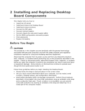
...you open the computer or perform any of the computer chassis. 21 2 Installing and Replacing Desktop Board Components This chapter tells you how to: • Install the I/O shield • Install and remove the Desktop Board • Install and remove memory • Connect the IDE cable • Connect internal headers • Connect chassis fan... by wearing an antistatic wrist strap and attaching it to disconnect power, telecommunications links, networks, or modems before you begin installing the Desktop Board: • Always follow the steps in each procedure in this chapter.
...you open the computer or perform any of the computer chassis. 21 2 Installing and Replacing Desktop Board Components This chapter tells you how to: • Install the I/O shield • Install and remove the Desktop Board • Install and remove memory • Connect the IDE cable • Connect internal headers • Connect chassis fan... by wearing an antistatic wrist strap and attaching it to disconnect power, telecommunications links, networks, or modems before you begin installing the Desktop Board: • Always follow the steps in each procedure in this chapter.

Product Guide
Page 25
... Serial Presence Detect Specification at: http://www.intel.com/technology/memory/ddr/specs/dda18c32_64_128x72ag_a.pdf The Desktop Board has one 240-pin DDR2 DIMM socket. Use DDR DIMMs 25 Installing and Replacing Desktop Board Components Installing and Removing Memory NOTE To be fully compliant with all applicable Intel SDRAM memory specifications, the boards require DIMMs that support the Serial Presence...
... Serial Presence Detect Specification at: http://www.intel.com/technology/memory/ddr/specs/dda18c32_64_128x72ag_a.pdf The Desktop Board has one 240-pin DDR2 DIMM socket. Use DDR DIMMs 25 Installing and Replacing Desktop Board Components Installing and Removing Memory NOTE To be fully compliant with all applicable Intel SDRAM memory specifications, the boards require DIMMs that support the Serial Presence...
Product Guide
Page 37
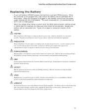
...; eksplosjonsfare hvis batteriet skiftes ut med feil type. VIKTIGT! Käytetyt paristot on mahdollista. Installing and Replacing Desktop Board Components Replacing the Battery A coin-cell battery (CR2032) powers the real-time clock and CMOS memory. The clock is plugged in CMOS RAM (for example, the date and time) might not be recycled where...
...; eksplosjonsfare hvis batteriet skiftes ut med feil type. VIKTIGT! Käytetyt paristot on mahdollista. Installing and Replacing Desktop Board Components Replacing the Battery A coin-cell battery (CR2032) powers the real-time clock and CMOS memory. The clock is plugged in CMOS RAM (for example, the date and time) might not be recycled where...
Product Guide
Page 43
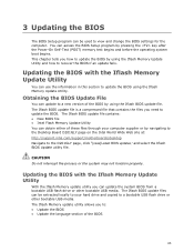
... File You can access the BIOS Setup program by navigating to the Desktop Board D201GLY page on the Intel World Wide Web site at: http://support.intel.com/support/motherboards/desktop Navigate to recover the BIOS if an update fails. Updating the BIOS with the Iflash Memory Update Utility You can be extracted locally to your computer supplier...
... File You can access the BIOS Setup program by navigating to the Desktop Board D201GLY page on the Intel World Wide Web site at: http://support.intel.com/support/motherboards/desktop Navigate to recover the BIOS if an update fails. Updating the BIOS with the Iflash Memory Update Utility You can be extracted locally to your computer supplier...
Product Guide
Page 45
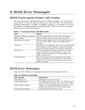
...powers up, then off for 0.5 second Off when update begins, then on for 0.5 second, then off for 0.5 second when processor initialization is powered off Memory error On-off (0.5 second each ) two times, then 3.0 second pause (off) between on-off blink pattern; On-off (0.5 second each ) three... did not find a device to display messages. repeat entire pattern (four on-off blinks and 3-second pause) until system is complete. Memory size has decreased since the last boot. pattern repeats until system is complete. repeat entire pattern (three on-off blinks and 3-second pause...
...powers up, then off for 0.5 second Off when update begins, then on for 0.5 second, then off for 0.5 second when processor initialization is powered off Memory error On-off (0.5 second each ) two times, then 3.0 second pause (off) between on-off blink pattern; On-off (0.5 second each ) three... did not find a device to display messages. repeat entire pattern (four on-off blinks and 3-second pause) until system is complete. Memory size has decreased since the last boot. pattern repeats until system is complete. repeat entire pattern (three on-off blinks and 3-second pause...


