Product Guide
Page 3
...: CAUTION Cautions warn the user about board layout, component installation, and regulatory requirements for technically qualified personnel. Intended Audience The Product Guide is not intended for other PC or embedded non-PC applications or other hardware components 3 Updating the BIOS: a description of how to important information. It is intended for Intel® Desktop Board D201GLY. iii
...: CAUTION Cautions warn the user about board layout, component installation, and regulatory requirements for technically qualified personnel. Intended Audience The Product Guide is not intended for other PC or embedded non-PC applications or other hardware components 3 Updating the BIOS: a description of how to important information. It is intended for Intel® Desktop Board D201GLY. iii
Product Guide
Page 5
...Desktop Board Features Supported Operating Systems 10 Desktop Board Components 11 Processor ...13 Main Memory ...13 Chipset ...14 Graphics Subsystem 14 Audio Subsystem 14 Input/Output (I/O) Controller 15 LAN Subsystem 15 LAN Subsystem Software 16 RJ-45 LAN Connector LEDs 16 Hi-Speed USB 2.0 Support 17 Enhanced IDE Interface 17 Expandability...17 BIOS...Overload 22 Observe Safety and Regulatory Requirements 22 Installing the I/O Shield 23 Installing and Removing the Desktop Board 24 Installing and Removing Memory 25 Installing DIMMs 25 Removing DIMMs 27 Connecting the IDE Cable ...
...Desktop Board Features Supported Operating Systems 10 Desktop Board Components 11 Processor ...13 Main Memory ...13 Chipset ...14 Graphics Subsystem 14 Audio Subsystem 14 Input/Output (I/O) Controller 15 LAN Subsystem 15 LAN Subsystem Software 16 RJ-45 LAN Connector LEDs 16 Hi-Speed USB 2.0 Support 17 Enhanced IDE Interface 17 Expandability...17 BIOS...Overload 22 Observe Safety and Regulatory Requirements 22 Installing the I/O Shield 23 Installing and Removing the Desktop Board 24 Installing and Removing Memory 25 Installing DIMMs 25 Removing DIMMs 27 Connecting the IDE Cable ...
Product Guide
Page 6
Intel Desktop Board D201GLY Product Guide Setting the Desktop Board Jumpers 34 Front Panel Audio Header/Jumper Block 34 BIOS Configuration Jumper 35 Clearing Passwords 36 Replacing the Battery 37 3 Updating the BIOS Updating the BIOS with the Iflash Memory Update Utility 43 Obtaining the BIOS Update File 43 Updating the BIOS with the Iflash Memory Update Utility 43 Recovering the BIOS 44...
Intel Desktop Board D201GLY Product Guide Setting the Desktop Board Jumpers 34 Front Panel Audio Header/Jumper Block 34 BIOS Configuration Jumper 35 Clearing Passwords 36 Replacing the Battery 37 3 Updating the BIOS Updating the BIOS with the Iflash Memory Update Utility 43 Obtaining the BIOS Update File 43 Updating the BIOS with the Iflash Memory Update Utility 43 Recovering the BIOS 44...
Product Guide
Page 7
... Regulations 53 14. Location of the Chassis Fan Header 32 12. Internal Headers 29 11. Installing a DIMM 26 9. Desktop Boards D201GLY Components 12 3. Feature Summary 9 2. Front Panel Audio Header/Jumper Block 35 8. BIOS Error Messages 45 11. Front Panel Header Signal Names 31 7. Lead-Free Board Markings 52 13. Safety Regulations 47 12. Intel Desktop Board D201GLY Components 11 2.
... Regulations 53 14. Location of the Chassis Fan Header 32 12. Internal Headers 29 11. Installing a DIMM 26 9. Desktop Boards D201GLY Components 12 3. Feature Summary 9 2. Front Panel Audio Header/Jumper Block 35 8. BIOS Error Messages 45 11. Front Panel Header Signal Names 31 7. Lead-Free Board Markings 52 13. Safety Regulations 47 12. Intel Desktop Board D201GLY Components 11 2.
Product Guide
Page 9
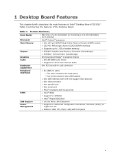
... BIOS Boot LAN Support • 10/100 Mb/s LAN Subsystem Power Management • Support for S3 • Wake on USB, PCI, PS/2, LAN, and front panel 9 no support for Advanced Configuration and Power Interface (ACPI); 1 Desktop Board Features This chapter briefly describes the main features of the Desktop Board. Table 1 summarizes the features of Intel® Desktop Board D201GLY...
... BIOS Boot LAN Support • 10/100 Mb/s LAN Subsystem Power Management • Support for S3 • Wake on USB, PCI, PS/2, LAN, and front panel 9 no support for Advanced Configuration and Power Interface (ACPI); 1 Desktop Board Features This chapter briefly describes the main features of the Desktop Board. Table 1 summarizes the features of Intel® Desktop Board D201GLY...
Product Guide
Page 10
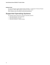
Intel Desktop Board D201GLY Product Guide Related Links: For more information about Desktop Board D201GLY, including the Technical Product Specification (TPS), BIOS updates, and device drivers, go to: http://support.intel.com/support/motherboards/desktop/ Supported Operating Systems The Desktop Board supports the following operating systems: • Microsoft Windows* XP Professional • Microsoft Windows XP Home • Microsoft Windows XP Starter Edition 10
Intel Desktop Board D201GLY Product Guide Related Links: For more information about Desktop Board D201GLY, including the Technical Product Specification (TPS), BIOS updates, and device drivers, go to: http://support.intel.com/support/motherboards/desktop/ Supported Operating Systems The Desktop Board supports the following operating systems: • Microsoft Windows* XP Professional • Microsoft Windows XP Home • Microsoft Windows XP Starter Edition 10
Product Guide
Page 12
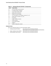
... panel header Battery BIOS configuration jumper Related Links: Go to the following links for more information about: • Desktop Board D201GLY • Audio software and utilities • LAN software and drivers http://www.intel.com/design/motherbd http://support.intel.com/support/motherboards/desktop http://www.intel.com/design/motherbd http://www.intel.com/design/motherbd 12 Intel Desktop Board D201GLY Product Guide Table...
... panel header Battery BIOS configuration jumper Related Links: Go to the following links for more information about: • Desktop Board D201GLY • Audio software and utilities • LAN software and drivers http://www.intel.com/design/motherbd http://support.intel.com/support/motherboards/desktop http://www.intel.com/design/motherbd http://www.intel.com/design/motherbd 12 Intel Desktop Board D201GLY Product Guide Table...
Product Guide
Page 13
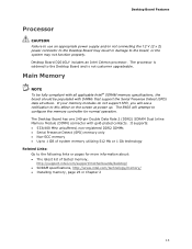
... Presence Detect (SPD) data structure. The processor is soldered to this effect on the screen at power up. The BIOS will see a notification to the Desktop Board and is not customer upgradeable. It supports: • 533/400 MHz unbuffered, non-registered DDR2 DIMMs • Serial...1 Gb technology Related Links: Go to the board, or the system may result in Chapter 2 13 Desktop Board D201GLY includes an Intel Celeron processor. Main Memory NOTE To be fully compliant with all applicable Intel® SDRAM memory specifications, the board should be populated with gold-plated contacts. If...
... Presence Detect (SPD) data structure. The processor is soldered to this effect on the screen at power up. The BIOS will see a notification to the Desktop Board and is not customer upgradeable. It supports: • 533/400 MHz unbuffered, non-registered DDR2 DIMMs • Serial...1 Gb technology Related Links: Go to the board, or the system may result in Chapter 2 13 Desktop Board D201GLY includes an Intel Celeron processor. Main Memory NOTE To be fully compliant with all applicable Intel® SDRAM memory specifications, the board should be populated with gold-plated contacts. If...
Product Guide
Page 17
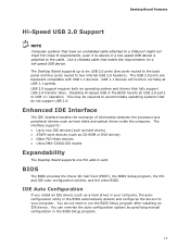
...as CD-ROM or DVD drives) • Older PIO Mode devices • Ultra DMA-33/66/100 modes Expandability The Desktop Board supports one PCI add-in the BIOS automatically detects and configures the device for a full-speed USB device. The interface supports: • Up to USB 1.1 ...IDE Interface The IDE interface handles the exchange of information between the processor and peripheral devices such as a hard drive) in the BIOS Setup program. 17 Desktop Board Features Hi-Speed USB 2.0 Support NOTE Computer systems that have an unshielded cable attached to a USB port might not meet FCC ...
...as CD-ROM or DVD drives) • Older PIO Mode devices • Ultra DMA-33/66/100 modes Expandability The Desktop Board supports one PCI add-in the BIOS automatically detects and configures the device for a full-speed USB device. The interface supports: • Up to USB 1.1 ...IDE Interface The IDE interface handles the exchange of information between the processor and peripheral devices such as a hard drive) in the BIOS Setup program. 17 Desktop Board Features Hi-Speed USB 2.0 Support NOTE Computer systems that have an unshielded cable attached to a USB port might not meet FCC ...
Product Guide
Page 18
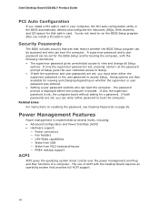
... booted. Setup options are then available for booting the computer, with the Desktop Board requires an operating system that restrict whether the BIOS Setup program can be set for the BIOS Setup and for viewing and changing depending on page 36. Intel Desktop Board D201GLY Product Guide PCI Auto Configuration If you can enter either the supervisor password...
... booted. Setup options are then available for booting the computer, with the Desktop Board requires an operating system that restrict whether the BIOS Setup program can be set for the BIOS Setup and for viewing and changing depending on page 36. Intel Desktop Board D201GLY Product Guide PCI Auto Configuration If you can enter either the supervisor password...
Product Guide
Page 21
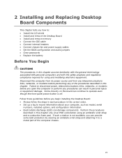
...Install the I/O shield • Install and remove the Desktop Board • Install and remove memory • Connect the IDE cable • Connect internal headers • Connect chassis fan and power supply cables • Set the BIOS configuration and audio jumpers • Clear passwords • ...in this chapter only at an ESD workstation using and modifying electronic equipment. Some circuitry on the board can damage components. 2 Installing and Replacing Desktop Board Components This chapter tells you open the computer or perform any of the computer chassis. 21 Disconnect ...
...Install the I/O shield • Install and remove the Desktop Board • Install and remove memory • Connect the IDE cable • Connect internal headers • Connect chassis fan and power supply cables • Set the BIOS configuration and audio jumpers • Clear passwords • ...in this chapter only at an ESD workstation using and modifying electronic equipment. Some circuitry on the board can damage components. 2 Installing and Replacing Desktop Board Components This chapter tells you open the computer or perform any of the computer chassis. 21 Disconnect ...
Product Guide
Page 35
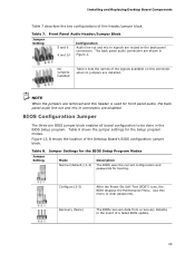
... installed. NOTE When the jumpers are removed and this connector when no jumpers are disabled. BIOS Configuration Jumper The three-pin BIOS jumper block enables all board configuration to the back panel connectors. Table 8 shows the jumper settings for booting. Configure...line out and mic-in signals are shown in the event of a failed BIOS update. 35 Table 7. Figure 13, B shows the location of the Desktop Board's BIOS configuration jumper block. Installing and Replacing Desktop Board Components Table 7 describes the two configurations of this menu to clear passwords. ...
... installed. NOTE When the jumpers are removed and this connector when no jumpers are disabled. BIOS Configuration Jumper The three-pin BIOS jumper block enables all board configuration to the back panel connectors. Table 8 shows the jumper settings for booting. Configure...line out and mic-in signals are shown in the event of a failed BIOS update. 35 Table 7. Figure 13, B shows the location of the Desktop Board's BIOS configuration jumper block. Installing and Replacing Desktop Board Components Table 7 describes the two configurations of this menu to clear passwords. ...
Product Guide
Page 37
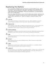
...;tts med felaktig batterityp. The clock is replaced with an equivalent one. When the voltage drops below a certain level, the BIOS Setup program settings stored in , the standby current from the power supply extends the life of three years. La mise au ...explosion if the battery is accurate to ± 13 minutes/year at 25 ºC with local environmental regulations. VIKTIGT! Installing and Replacing Desktop Board Components Replacing the Battery A coin-cell battery (CR2032) powers the real-time clock and CMOS memory. VARO Räjähdysvaara, jos pariston...
...;tts med felaktig batterityp. The clock is replaced with an equivalent one. When the voltage drops below a certain level, the BIOS Setup program settings stored in , the standby current from the power supply extends the life of three years. La mise au ...explosion if the battery is accurate to ± 13 minutes/year at 25 ºC with local environmental regulations. VIKTIGT! Installing and Replacing Desktop Board Components Replacing the Battery A coin-cell battery (CR2032) powers the real-time clock and CMOS memory. VARO Räjähdysvaara, jos pariston...
Product Guide
Page 43
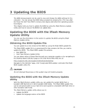
... a compressed file that contains the files you how to update the BIOS by navigating to the Desktop Board D201GLY page on the Intel World Wide Web site at: http://support.intel.com/support/motherboards/desktop Navigate to : • Update the BIOS • Update the language section of the BIOS by pressing the key after the Power-On Self-Test (POST...
... a compressed file that contains the files you how to update the BIOS by navigating to the Desktop Board D201GLY page on the Intel World Wide Web site at: http://support.intel.com/support/motherboards/desktop Navigate to : • Update the BIOS • Update the language section of the BIOS by pressing the key after the Power-On Self-Test (POST...
Product Guide
Page 44
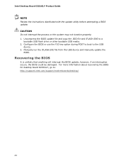
... the USB device. 3. For more information about recovering the BIOS for desktop board D201GLY, go to: http://support.intel.com/support/motherboards/desktop/ 44 however, if an interruption occurs, the BIOS could be damaged. Intel Desktop Board D201GLY Product Guide NOTE Review the instructions distributed with the update utility before attempting a BIOS update. Recovering the BIOS It is unlikely that anything will interrupt the...
... the USB device. 3. For more information about recovering the BIOS for desktop board D201GLY, go to: http://support.intel.com/support/motherboards/desktop/ 44 however, if an interruption occurs, the BIOS could be damaged. Intel Desktop Board D201GLY Product Guide NOTE Review the instructions distributed with the update utility before attempting a BIOS update. Recovering the BIOS It is unlikely that anything will interrupt the...
Product Guide
Page 45
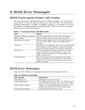
...times, then 3.0 second pause (off) between on -off blink pattern; repeat entire pattern (three on -off blinks and 3-second pause) until BIOS update is incorrect. Table 10. repeat entire pattern (four on -off blink pattern; If no memory was removed, then memory may have been corrupted...until system is powered off Thermal warning On-off (0.5 second each . Front-panel Power LED Blink Codes Type Processor initialization complete POST complete BIOS update in progress Video error Pattern On when system powers up, then off for 0.5 second On when system powers up, then off ...
...times, then 3.0 second pause (off) between on -off blink pattern; repeat entire pattern (three on -off blinks and 3-second pause) until BIOS update is incorrect. Table 10. repeat entire pattern (four on -off blink pattern; If no memory was removed, then memory may have been corrupted...until system is powered off Thermal warning On-off (0.5 second each . Front-panel Power LED Blink Codes Type Processor initialization complete POST complete BIOS update in progress Video error Pattern On when system powers up, then off for 0.5 second On when system powers up, then off ...


