
Product Specification
Page 6
Intel Desktop Board D101GGC Technical Product Specification 2.9 Mechanical Considerations 46 2.9.1 Form Factor 46 2.9.2 I/O Shield...47 2.10 Electrical Considerations 48 2.10.1 DC Loading...48 2.10.2 Add-in Board Considerations 48 2.10.3 Fan Connector Current Capability 49 2.10.4 Power Supply Considerations 49 2.11 Thermal Considerations 50 2.12 Reliability...52 2.13 Environmental ...53 2.14 Regulatory Compliance 54 2.14...
Intel Desktop Board D101GGC Technical Product Specification 2.9 Mechanical Considerations 46 2.9.1 Form Factor 46 2.9.2 I/O Shield...47 2.10 Electrical Considerations 48 2.10.1 DC Loading...48 2.10.2 Add-in Board Considerations 48 2.10.3 Fan Connector Current Capability 49 2.10.4 Power Supply Considerations 49 2.11 Thermal Considerations 50 2.12 Reliability...52 2.13 Environmental ...53 2.14 Regulatory Compliance 54 2.14...
Product Specification
Page 10
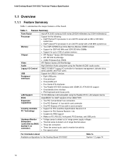
... Express x16 bus add-in card connector • Support for PCI Local Bus Specification Revision 2.2 • Support for the Desktop Board D101GGC Refer to detect out of the board. Intel Desktop Board D101GGC Technical Product Specification 1.1 Overview 1.1.1 Feature Summary Table 1 summarizes the major features of range thermal values • Three fan connectors •...; Suspend to RAM support • Wake on PCI, RS-232, front panel, PS/2 devices, and USB ports • Voltage sense to detect out of range power supply voltages • Thermal sense to Section 1.2, page 14 10
... Express x16 bus add-in card connector • Support for PCI Local Bus Specification Revision 2.2 • Support for the Desktop Board D101GGC Refer to detect out of the board. Intel Desktop Board D101GGC Technical Product Specification 1.1 Overview 1.1.1 Feature Summary Table 1 summarizes the major features of range thermal values • Three fan connectors •...; Suspend to RAM support • Wake on PCI, RS-232, front panel, PS/2 devices, and USB ports • Voltage sense to detect out of range power supply voltages • Thermal sense to Section 1.2, page 14 10
Product Specification
Page 14
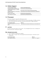
... Product Specification 1.2 Online Support To find information about Power supply connectors Refer to Table 3 on web site above. Intel Desktop Board D101GGC under "Desktop Board Products" or "Desktop Board Support" Available configurations for the D101GGC board Refer to support the following processors: • Intel Pentium 4 processor in an LGA775 processor socket with an 800 or 533...
... Product Specification 1.2 Online Support To find information about Power supply connectors Refer to Table 3 on web site above. Intel Desktop Board D101GGC under "Desktop Board Products" or "Desktop Board Support" Available configurations for the D101GGC board Refer to support the following processors: • Intel Pentium 4 processor in an LGA775 processor socket with an 800 or 533...
Product Specification
Page 18
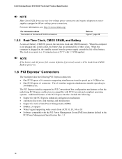
Intel Desktop Board D101GGC Technical Product Specification NOTE Many Serial ATA drives use new low-voltage power connectors and require adaptors or power supplies equipped with PCI Conventional compliant operating systems. Additional features of the Serial ATA IDE connectors Refer to Figure 7, page 38 1.5.5 Real-Time Clock, CMOS SRAM, and Battery A coin-cell battery (CR2032) powers...with the PCI Power Management Event (PME) mechanism defined in , the standby current from the power supply extends the life of three years. The clock is compatible with low-voltage power connectors. For ...
Intel Desktop Board D101GGC Technical Product Specification NOTE Many Serial ATA drives use new low-voltage power connectors and require adaptors or power supplies equipped with PCI Conventional compliant operating systems. Additional features of the Serial ATA IDE connectors Refer to Figure 7, page 38 1.5.5 Real-Time Clock, CMOS SRAM, and Battery A coin-cell battery (CR2032) powers...with the PCI Power Management Event (PME) mechanism defined in , the standby current from the power supply extends the life of three years. The clock is compatible with low-voltage power connectors. For ...

Product Specification
Page 23
...; Internal ambient temperature sensor • Two remote thermal diode sensors for direct monitoring of processor temperature and ambient temperature sensing • Power supply monitoring of the fan connectors Refer to Section 1.11.2.2, page 27 1.10.2 Chassis Intrusion and Detection The board supports a chassis security... switch the fans on or off as needed • SMBus interface 1.10.1 Fan Monitoring Fan monitoring can be implemented using Intel® Desktop Utilities, LANDesk* software, or thirdparty software. The security feature uses a mechanical switch on the chassis that attaches...
...; Internal ambient temperature sensor • Two remote thermal diode sensors for direct monitoring of processor temperature and ambient temperature sensing • Power supply monitoring of the fan connectors Refer to Section 1.11.2.2, page 27 1.10.2 Chassis Intrusion and Detection The board supports a chassis security... switch the fans on or off as needed • SMBus interface 1.10.1 Fan Monitoring Fan monitoring can be implemented using Intel® Desktop Utilities, LANDesk* software, or thirdparty software. The security feature uses a mechanical switch on the chassis that attaches...
Product Specification
Page 25
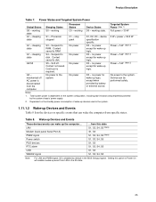
...computer from the computer. Wake-up Devices and Events These devices/events can wake up logic. device specification specific. 5 W < power < 52.5 W G1 - S4 - S5 - No power No power No power D3 - no power except for wake-up Devices and Events Table 8 lists the devices or specific events that can be performed safely. Table 8. ... will enable a wake-up logic. Context saved to the system. Cold boot is disabled by the system chassis' power supply. 2. Setting this state S1, S3, S4, S5 (Note) S1, S3 S1, S3, S4, S5 (Note) S1, S3, S4, S5 S1, S3 S1, S3, S4,...
...computer from the computer. Wake-up Devices and Events These devices/events can wake up logic. device specification specific. 5 W < power < 52.5 W G1 - S4 - S5 - No power No power No power D3 - no power except for wake-up Devices and Events Table 8 lists the devices or specific events that can be performed safely. Table 8. ... will enable a wake-up logic. Context saved to the system. Cold boot is disabled by the system chassis' power supply. 2. Setting this state S1, S3, S4, S5 (Note) S1, S3 S1, S3, S4, S5 (Note) S1, S3, S4, S5 S1, S3 S1, S3, S4,...
Product Specification
Page 26
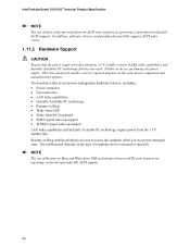
... devices to do so can damage the power supply. NOTE The use of these wake-up support LAN wake capabilities and Instantly Available PC technology require power from the +5 V standby line. The method used . Intel Desktop Board D101GGC Technical Product Specification NOTE The use of Resume... on Ring and Wake from USB technologies from an ACPI state requires an operating system that the power supply provides adequate +5 V...
... devices to do so can damage the power supply. NOTE The use of these wake-up support LAN wake capabilities and Instantly Available PC technology require power from the +5 V standby line. The method used . Intel Desktop Board D101GGC Technical Product Specification NOTE The use of Resume... on Ring and Wake from USB technologies from an ACPI state requires an operating system that the power supply provides adequate +5 V...
Product Specification
Page 27
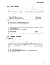
... with ACPI in the following ways: • The PCI Express WAKE# signal • The PCI Conventional bus PME# signal for the power supply must be set using the Last Power State feature in the S3, S4, or S5 state. • Each fan connector is off as needed. • All fan connectors... a wake-up signal that can adjust the fan speed or switch the fan on or off the system power through a network. When an ACPI-enabled system receives the correct command, the power supply removes all non-standby voltages. LAN wake capabilities enable remote wake-up the computer. When resuming from an...
... with ACPI in the following ways: • The PCI Express WAKE# signal • The PCI Conventional bus PME# signal for the power supply must be set using the Last Power State feature in the S3, S4, or S5 state. • Each fan connector is off as needed. • All fan connectors... a wake-up signal that can adjust the fan speed or switch the fan on or off the system power through a network. When an ACPI-enabled system receives the correct command, the power supply removes all non-standby voltages. LAN wake capabilities enable remote wake-up the computer. When resuming from an...
Product Specification
Page 28
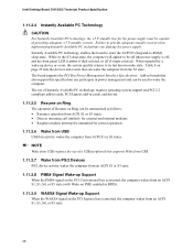
... add-in BIOS). 1.11.2.9 WAKE# Signal Wake-up device or event, the system quickly returns to its last known wake state. Intel Desktop Board D101GGC Technical Product Specification 1.11.2.4 Instantly Available PC Technology CAUTION For Instantly Available PC technology, the +5 V standby line for correct operation 1.... S3 states • Detects incoming call similarly for external and internal modems • Requires modem interrupt be unmasked for the power supply must be used to wake the computer. Instantly Available PC technology enables the board to enter the ACPI S3 (Suspend-to be ...
... add-in BIOS). 1.11.2.9 WAKE# Signal Wake-up device or event, the system quickly returns to its last known wake state. Intel Desktop Board D101GGC Technical Product Specification 1.11.2.4 Instantly Available PC Technology CAUTION For Instantly Available PC technology, the +5 V standby line for correct operation 1.... S3 states • Detects incoming call similarly for external and internal modems • Requires modem interrupt be unmasked for the power supply must be used to wake the computer. Instantly Available PC technology enables the board to enter the ACPI S3 (Suspend-to be ...

Product Specification
Page 41
... on/off) 17 Ground 18 Ground 19 Ground 20 No connect 21 +5 V 22 +5 V 23 +5 V (Note) 24 Ground (Note) Note: When using a power supply with a 2 x 10 main power cable, attach that cable on Intel Desktop boards. Failure to the processor voltage regulator and must always be unconnected. This connector is compatible with either 2 x 10 or...
... on/off) 17 Ground 18 Ground 19 Ground 20 No connect 21 +5 V 22 +5 V 23 +5 V (Note) 24 Ground (Note) Note: When using a power supply with a 2 x 10 main power cable, attach that cable on Intel Desktop boards. Failure to the processor voltage regulator and must always be unconnected. This connector is compatible with either 2 x 10 or...

Product Specification
Page 44
...ground for at least 50 ms to signal the power supply to switch on or off. (The time requirement is due to internal debounce circuitry on the board.) At least two seconds must pass before the power supply will recognize another on/off signal. 2.7.3 Front... Panel USB Connectors 44 Power (+5 V DC) One D− USB Port D+ 1 2 3 4 5 6 Power (+5 V DC) D− One USB D+ Port Ground 7 8 Ground Key (no pin) 10 No Connect OM15963 Figure 9. Actual LED colors are suggested colors only. speed USB devices. Intel Desktop Board D101GGC Technical Product Specification NOTE...
...ground for at least 50 ms to signal the power supply to switch on or off. (The time requirement is due to internal debounce circuitry on the board.) At least two seconds must pass before the power supply will recognize another on/off signal. 2.7.3 Front... Panel USB Connectors 44 Power (+5 V DC) One D− USB Port D+ 1 2 3 4 5 6 Power (+5 V DC) D− One USB D+ Port Ground 7 8 Ground Key (no pin) 10 No Connect OM15963 Figure 9. Actual LED colors are suggested colors only. speed USB devices. Intel Desktop Board D101GGC Technical Product Specification NOTE...
Product Specification
Page 48
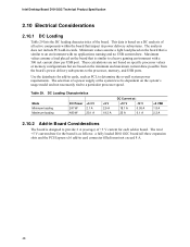
Intel Desktop Board D101GGC Technical Product Specification 2.10 Electrical Considerations 2.10.1 DC Loading Table 29 lists the DC loading characteristics of +5 V current for each add-in board. These calculations are not based on specific processor values or memory configurations but are based on a DC analysis of a power supply at : +12 V -12 V 18.1 A 0.05 A 25 A 0.1 A +5 VSB...
Intel Desktop Board D101GGC Technical Product Specification 2.10 Electrical Considerations 2.10.1 DC Loading Table 29 lists the DC loading characteristics of +5 V current for each add-in board. These calculations are not based on specific processor values or memory configurations but are based on a DC analysis of a power supply at : +12 V -12 V 18.1 A 0.05 A 25 A 0.1 A +5 VSB...

Product Specification
Page 49
...All timing parameters • All voltage tolerances 49 System integrators should refer to the power usage values listed in Table 29 when selecting a power supply for the power supply must comply with the board. The power supply must be connected to the processor fan connector, not to a chassis fan connector.... Fan Connector Processor fan Front chassis fan Rear chassis fan Maximum Available Current 3000 mA 1500 mA 1500 mA 2.10.4 Power Supply Considerations CAUTION The +5 V standby line for use with the following recommendations found in onboard component damage that will depend on...
...All timing parameters • All voltage tolerances 49 System integrators should refer to the power usage values listed in Table 29 when selecting a power supply for the power supply must comply with the board. The power supply must be connected to the processor fan connector, not to a chassis fan connector.... Fan Connector Processor fan Front chassis fan Rear chassis fan Maximum Available Current 3000 mA 1500 mA 1500 mA 2.10.4 Power Supply Considerations CAUTION The +5 V standby line for use with the following recommendations found in onboard component damage that will depend on...
Product Specification
Page 62
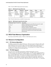
...information Displays processor and memory configuration Configures advanced features available through the chipset Sets passwords and security features Power Boot Configures power management features and power supply controls Selects boot options Exit Saves or discards changes to be onboard or add-in the BIOS Setup ... configuration values for use by the add-in card. 3.3.2 PCI IDE Support If you select Auto in cards. Intel Desktop Board D101GGC Technical Product Specification Table 37 lists the BIOS Setup program menu features. To take advantage of each drive and configures...
...information Displays processor and memory configuration Configures advanced features available through the chipset Sets passwords and security features Power Boot Configures power management features and power supply controls Selects boot options Exit Saves or discards changes to be onboard or add-in the BIOS Setup ... configuration values for use by the add-in card. 3.3.2 PCI IDE Support If you select Auto in cards. Intel Desktop Board D101GGC Technical Product Specification Table 37 lists the BIOS Setup program menu features. To take advantage of each drive and configures...

Intel Desktop Board D101GGC Product Guide English
Page 5
... and IDE Auto Configuration 17 PCI and PCI Express Auto Configuration 17 Security Passwords ...18 Chassis Intrusion...18 Power Management Features 18 ACPI...18 Power Connectors...18 Fan Connectors...19 Suspend to RAM (Instantly Available PC Technology 19 Wake from USB...20 Wake ...21 Battery...21 Real-Time Clock...21 2 Installing and Replacing Desktop Board Components Before You Begin ...23 Installation Precautions ...24 Prevent Power Supply Overload 24 Observe Safety and Regulatory Requirements 24 Installing the I/O Shield ...25 Installing and Removing the Desktop Board 26 Installing and ...
... and IDE Auto Configuration 17 PCI and PCI Express Auto Configuration 17 Security Passwords ...18 Chassis Intrusion...18 Power Management Features 18 ACPI...18 Power Connectors...18 Fan Connectors...19 Suspend to RAM (Instantly Available PC Technology 19 Wake from USB...20 Wake ...21 Battery...21 Real-Time Clock...21 2 Installing and Replacing Desktop Board Components Before You Begin ...23 Installation Precautions ...24 Prevent Power Supply Overload 24 Observe Safety and Regulatory Requirements 24 Installing the I/O Shield ...25 Installing and Removing the Desktop Board 26 Installing and ...
Intel Desktop Board D101GGC Product Guide English
Page 7
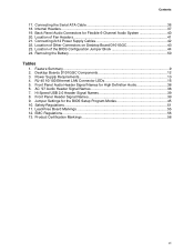
.... Removing the Battery 50 Tables 1. RJ-45 10/100 Ethernet LAN Connector LEDs 16 5. EMC Regulations...56 13. Power Supply Requirements 13 4. Location of Other Connectors on Desktop Board D101GGC 43 23. Connecting 2x12 Power Supply Cables 42 22. Front Panel Audio Header Signal Names for High Definition Audio 38 6. Front Panel Header Signal Names...
.... Removing the Battery 50 Tables 1. RJ-45 10/100 Ethernet LAN Connector LEDs 16 5. EMC Regulations...56 13. Power Supply Requirements 13 4. Location of Other Connectors on Desktop Board D101GGC 43 23. Connecting 2x12 Power Supply Cables 42 22. Front Panel Audio Header Signal Names for High Definition Audio 38 6. Front Panel Header Signal Names...
Intel Desktop Board D101GGC Product Guide English
Page 13
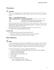
..., page 41 in the LGA775 package. The supported processors list for 10 ms ATX12V (version 2.0 or greater) compliant power supply Desktop board D101GGC supports an Intel processor in Chapter 2 Main Memory NOTE To be fully compliant with gold-plated contacts • Unbuffered, non-registered DIMMs • Serial Presence Detect (SPD) memory ...
..., page 41 in the LGA775 package. The supported processors list for 10 ms ATX12V (version 2.0 or greater) compliant power supply Desktop board D101GGC supports an Intel processor in Chapter 2 Main Memory NOTE To be fully compliant with gold-plated contacts • Unbuffered, non-registered DIMMs • Serial Presence Detect (SPD) memory ...
Intel Desktop Board D101GGC Product Guide English
Page 19
...PC technology enables the board to enter the ACPI S3 (Suspend-to support multiple wake events from the PCI and/or USB buses exceeds power supply capacity, the desktop board may lose register settings stored in Figure 3, is lit when there is indicated by a wake-up device or... enough standby current to be off . Suspend to its last known awake state. The desktop board's standby power indicator, shown in memory. Power supplies used with this feature can damage the power supply and/or effect ACPI S3 sleep state functionality. Desktop Board Features Fan Connectors The desktop board has a ...
...PC technology enables the board to enter the ACPI S3 (Suspend-to support multiple wake events from the PCI and/or USB buses exceeds power supply capacity, the desktop board may lose register settings stored in Figure 3, is lit when there is indicated by a wake-up device or... enough standby current to be off . Suspend to its last known awake state. The desktop board's standby power indicator, shown in memory. Power supplies used with this feature can damage the power supply and/or effect ACPI S3 sleep state functionality. Desktop Board Features Fan Connectors The desktop board has a ...
Intel Desktop Board D101GGC Product Guide English
Page 24
...calculated total current loads of all warnings and cautions in this section and the instructions supplied with regional laws and regulations. Prevent Power Supply Overload Do not overload the power supply output. Observe Safety and Regulatory Requirements Read and adhere to qualified technical personnel. ...module suppliers, you install and test the Intel desktop board, observe all the modules within the computer is less than the output current rating of each of the power supplies output circuits. Intel Desktop Board D101GGC Product Guide Installation Precautions When you increase safety...
...calculated total current loads of all warnings and cautions in this section and the instructions supplied with regional laws and regulations. Prevent Power Supply Overload Do not overload the power supply output. Observe Safety and Regulatory Requirements Read and adhere to qualified technical personnel. ...module suppliers, you install and test the Intel desktop board, observe all the modules within the computer is less than the output current rating of each of the power supplies output circuits. Intel Desktop Board D101GGC Product Guide Installation Precautions When you increase safety...
Intel Desktop Board D101GGC Product Guide English
Page 34
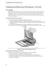
... Express x16 card from the RM: 1. Remove the screw that it is not fully seated in the PCI Express x16 connector before you power on the system. Installing a PCI Express x16 Card 1. Place the card in the PCI Express x16 connector and press down on the ...(Figure 15, A). 3. Depending on the over-current protection of the power supply, certain board components and/or traces may result across the PCI Express connector pins. If the card is completely seated in the card. 4. Intel Desktop Board D101GGC Product Guide Installing and Removing a PCI Express* x16 Card CAUTION When installing...
... Express x16 card from the RM: 1. Remove the screw that it is not fully seated in the PCI Express x16 connector before you power on the system. Installing a PCI Express x16 Card 1. Place the card in the PCI Express x16 connector and press down on the ...(Figure 15, A). 3. Depending on the over-current protection of the power supply, certain board components and/or traces may result across the PCI Express connector pins. If the card is completely seated in the card. 4. Intel Desktop Board D101GGC Product Guide Installing and Removing a PCI Express* x16 Card CAUTION When installing...


