
Product Specification
Page 1
Current characterized errata are documented in the Intel Desktop Board D101GGC Specification Update. Intel® Desktop Board D101GGC Technical Product Specification November 2005 Order Number: D36105-002US The Intel® Desktop Board D101GGC may contain design defects or errors known as errata that may cause the product to deviate from published specifications.
Current characterized errata are documented in the Intel Desktop Board D101GGC Specification Update. Intel® Desktop Board D101GGC Technical Product Specification November 2005 Order Number: D36105-002US The Intel® Desktop Board D101GGC may contain design defects or errors known as errata that may cause the product to deviate from published specifications.
Product Specification
Page 2
...-333, other countries. * Other names and brands may make changes to deviate from future changes to only standard Intel Desktop Board D101GGC with BIOS identifier GC11010N.86A. Copies of documents and other materials and information does not provide any license, express ... PROPERTY RIGHTS IS GRANTED BY THIS DOCUMENT. Revision History Revision -001 -002 Revision History First release of the Intel® Desktop Board D101GGC Technical Product Specification. Summary of changes: corrected name of Northbridge component to obtain the latest specifications before being incorporated...
...-333, other countries. * Other names and brands may make changes to deviate from future changes to only standard Intel Desktop Board D101GGC with BIOS identifier GC11010N.86A. Copies of documents and other materials and information does not provide any license, express ... PROPERTY RIGHTS IS GRANTED BY THIS DOCUMENT. Revision History Revision -001 -002 Revision History First release of the Intel® Desktop Board D101GGC Technical Product Specification. Summary of changes: corrected name of Northbridge component to obtain the latest specifications before being incorporated...
Product Specification
Page 3
... intended for the Intel® Desktop Board D101GGC. What This Document Contains Chapter 1 2 Description A description of the hardware used on the Desktop Board D101GGC A map of the resources of this specification. Preface This Technical Product Specification (TPS) specifies the board layout, components,... the standard product and available manufacturing options. Not all specifications of the Desktop Board Typographical Conventions This section contains information about the Desktop Board D101GGC and its components to help you avoid damaging hardware or losing data. CAUTION...
... intended for the Intel® Desktop Board D101GGC. What This Document Contains Chapter 1 2 Description A description of the hardware used on the Desktop Board D101GGC A map of the resources of this specification. Preface This Technical Product Specification (TPS) specifies the board layout, components,... the standard product and available manufacturing options. Not all specifications of the Desktop Board Typographical Conventions This section contains information about the Desktop Board D101GGC and its components to help you avoid damaging hardware or losing data. CAUTION...
Product Specification
Page 4
... ending with a lowercase h indicates a hexadecimal value. This symbol is used to identify an active-low signal (such as USBP0#) When used in the 5J area. Intel Desktop Board D101GGC Technical Product Specification Other Common Notation # (NxnX) GB GB/sec KB Kbit kbits/sec MB MB/sec Mbit Mbit/sec xxh x.x V * Used after a signal name... at 5J. It is the first connector in the description of a component, N indicates component type, xn are the relative coordinates of its location on the board, and X is the instance of their respective owners.
... ending with a lowercase h indicates a hexadecimal value. This symbol is used to identify an active-low signal (such as USBP0#) When used in the 5J area. Intel Desktop Board D101GGC Technical Product Specification Other Common Notation # (NxnX) GB GB/sec KB Kbit kbits/sec MB MB/sec Mbit Mbit/sec xxh x.x V * Used after a signal name... at 5J. It is the first connector in the description of a component, N indicates component type, xn are the relative coordinates of its location on the board, and X is the instance of their respective owners.
Product Specification
Page 6
Intel Desktop Board D101GGC Technical Product Specification 2.9 Mechanical Considerations 46 2.9.1 Form Factor 46 2.9.2 I/O Shield...47 2.10 Electrical Considerations 48 2.10.1 DC Loading...48 2.10.2 Add-in Board Considerations 48 2.10.3 Fan Connector Current Capability 49 2.10.4 Power Supply... Union Declaration of Conformity Statement 54 2.14.3 Product Ecology Statements 56 2.14.4 EMC Regulations 59 2.14.5 Product Certification Markings (Board Level 60 3 Overview of BIOS Features 3.1 Introduction ...61 3.2 BIOS Flash Memory Organization 62 3.3 Resource Configuration 62 3.3.1 PCI ...
Intel Desktop Board D101GGC Technical Product Specification 2.9 Mechanical Considerations 46 2.9.1 Form Factor 46 2.9.2 I/O Shield...47 2.10 Electrical Considerations 48 2.10.1 DC Loading...48 2.10.2 Add-in Board Considerations 48 2.10.3 Fan Connector Current Capability 49 2.10.4 Power Supply... Union Declaration of Conformity Statement 54 2.14.3 Product Ecology Statements 56 2.14.4 EMC Regulations 59 2.14.5 Product Certification Markings (Board Level 60 3 Overview of BIOS Features 3.1 Introduction ...61 3.2 BIOS Flash Memory Organization 62 3.3 Resource Configuration 62 3.3.1 PCI ...
Product Specification
Page 10
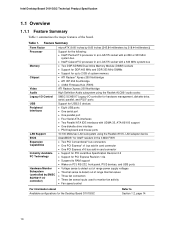
Intel Desktop Board D101GGC Technical Product Specification 1.1 Overview 1.1.1 Feature Summary Table 1 summarizes the major features of range thermal values • Three fan connectors • Three fan sense inputs used ... device AwardBIOS* for Intel® resident in the 4 Mbit FWH • Two PCI Conventional* bus connectors • One PCI Express* x1 bus add-in card connector • One PCI Express x16 bus add-in card connector • Support for PCI Local Bus Specification Revision 2.2 • Support for the Desktop Board D101GGC Refer to detect...
Intel Desktop Board D101GGC Technical Product Specification 1.1 Overview 1.1.1 Feature Summary Table 1 summarizes the major features of range thermal values • Three fan connectors • Three fan sense inputs used ... device AwardBIOS* for Intel® resident in the 4 Mbit FWH • Two PCI Conventional* bus connectors • One PCI Express* x1 bus add-in card connector • One PCI Express x16 bus add-in card connector • Support for PCI Local Bus Specification Revision 2.2 • Support for the Desktop Board D101GGC Refer to detect...
Product Specification
Page 12
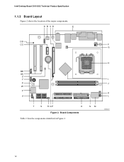
Board Components Table 2 lists the components identified in Figure 2. A B CD E DD CC F G H BB AA Z Y I X J W V K U L T S RQP O Figure 2. NM OM18247 12 Intel Desktop Board D101GGC Technical Product Specification 1.1.3 Board Layout Figure 2 shows the location of the major components.
Board Components Table 2 lists the components identified in Figure 2. A B CD E DD CC F G H BB AA Z Y I X J W V K U L T S RQP O Figure 2. NM OM18247 12 Intel Desktop Board D101GGC Technical Product Specification 1.1.3 Board Layout Figure 2 shows the location of the major components.
Product Specification
Page 14
... Product Specification 1.2 Online Support To find information about Power supply connectors Refer to Section 2.7.2.1, page 41 14 Intel Desktop Board D101GGC under "Desktop Board Products" or "Desktop Board Support" Available configurations for a list of unsupported processors can damage the board, the processor, and the power supply. # INTEGRATOR'S NOTE • Use only ATX12V-compliant power supplies. • Refer to Table...
... Product Specification 1.2 Online Support To find information about Power supply connectors Refer to Section 2.7.2.1, page 41 14 Intel Desktop Board D101GGC under "Desktop Board Products" or "Desktop Board Support" Available configurations for a list of unsupported processors can damage the board, the processor, and the power supply. # INTEGRATOR'S NOTE • Use only ATX12V-compliant power supplies. • Refer to Table...
Product Specification
Page 16
...• Four ports are routed to two separate front panel USB connectors NOTE Computer systems that meets the requirements for all ports. Intel Desktop Board D101GGC Technical Product Specification 1.5 ATI Radeon* Xpress 200 Chipset The ATI Radeon Xpress 200 chipset consists of the following devices: • ...ATI Radeon Xpress 200 Northbridge • IXP 450 Southbridge The ATI Radeon Xpress 200 Northbridge is a centralized controller for Intel. 1.5.3 USB The board supports up to eight USB 2.0 ports, supports UHCI and EHCI, and uses UHCI- The IXP 450 is attached to the cable...
...• Four ports are routed to two separate front panel USB connectors NOTE Computer systems that meets the requirements for all ports. Intel Desktop Board D101GGC Technical Product Specification 1.5 ATI Radeon* Xpress 200 Chipset The ATI Radeon Xpress 200 chipset consists of the following devices: • ...ATI Radeon Xpress 200 Northbridge • IXP 450 Southbridge The ATI Radeon Xpress 200 Northbridge is a centralized controller for Intel. 1.5.3 USB The board supports up to eight USB 2.0 ports, supports UHCI and EHCI, and uses UHCI- The IXP 450 is attached to the cable...
Product Specification
Page 18
... Rev. 1.1 18 For more information, see: http://www.serialata.org/ For information about The location of the battery. Intel Desktop Board D101GGC Technical Product Specification NOTE Many Serial ATA drives use new low-voltage power connectors and require adaptors or power supplies equipped with... 3.3 VSB applied. When the computer is accurate to ± 13 minutes/year at power-on. 1.6 PCI Express* Connectors The board provides the following : • Support for the PCI Express enhanced configuration mechanism • Automatic discovery, link training, and initialization •...
... Rev. 1.1 18 For more information, see: http://www.serialata.org/ For information about The location of the battery. Intel Desktop Board D101GGC Technical Product Specification NOTE Many Serial ATA drives use new low-voltage power connectors and require adaptors or power supplies equipped with... 3.3 VSB applied. When the computer is accurate to ± 13 minutes/year at power-on. 1.6 PCI Express* Connectors The board provides the following : • Support for the PCI Express enhanced configuration mechanism • Automatic discovery, link training, and initialization •...

Product Specification
Page 20
...software and drivers Refer to function, a front panel daughter card that is designed for Intel High Definition Audio must be permanent. 1.8.1 Audio Subsystem Software Audio software and drivers are available from Intel's World Wide Web site. The audio subsystem features: • ATI IXP 450 ... Microphone boost # INTEGRATOR'S NOTE For the front panel jack sensing and automatic retasking feature to Section 1.2, page 14 20 Intel Desktop Board D101GGC Technical Product Specification 1.8 High Definition Audio Subsystem The board includes a flexible 6-channel audio subsystem based on an...
...software and drivers Refer to function, a front panel daughter card that is designed for Intel High Definition Audio must be permanent. 1.8.1 Audio Subsystem Software Audio software and drivers are available from Intel's World Wide Web site. The audio subsystem features: • ATI IXP 450 ... Microphone boost # INTEGRATOR'S NOTE For the front panel jack sensing and automatic retasking feature to Section 1.2, page 14 20 Intel Desktop Board D101GGC Technical Product Specification 1.8 High Definition Audio Subsystem The board includes a flexible 6-channel audio subsystem based on an...

Product Specification
Page 22
...data rate is selected. 100 Mbits/sec data rate is established. LAN Connector LED Locations Table 5 describes the LED states when the board is powered up and the 10/100 Mbits/sec LAN subsystem is not established. Green LED Yellow LED OM15076 Figure 4. For information ... page 14 22 LAN Connector LED States LED Color Green Yellow LED State Off On Blinking Off On Condition LAN link is operating. Intel Desktop Board D101GGC Technical Product Specification 1.9 LAN Subsystem The LAN subsystem consists of the following: • Realtek 8101L LAN adapter device for 10/100 Mbits...
...data rate is selected. 100 Mbits/sec data rate is established. LAN Connector LED Locations Table 5 describes the LED states when the board is powered up and the 10/100 Mbits/sec LAN subsystem is not established. Green LED Yellow LED OM15076 Figure 4. For information ... page 14 22 LAN Connector LED States LED Color Green Yellow LED State Off On Blinking Off On Condition LAN link is operating. Intel Desktop Board D101GGC Technical Product Specification 1.9 LAN Subsystem The LAN subsystem consists of the following: • Realtek 8101L LAN adapter device for 10/100 Mbits...
Product Specification
Page 24
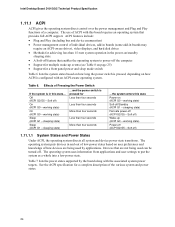
...include: • Plug and Play (including bus and device enumeration) • Power management control of individual devices, add-in boards (some add-in boards may require an ACPI-aware driver), video displays, and hard disk drives • Methods for achieving less than four seconds ......on (ACPI G0 - Devices that are being used by the board along with this board requires an operating system that enables the operating system to put the system as a whole into a low-power state. Intel Desktop Board D101GGC Technical Product Specification 1.11.1 ACPI ACPI gives the operating system ...
...include: • Plug and Play (including bus and device enumeration) • Power management control of individual devices, add-in boards (some add-in boards may require an ACPI-aware driver), video displays, and hard disk drives • Methods for achieving less than four seconds ......on (ACPI G0 - Devices that are being used by the board along with this board requires an operating system that enables the operating system to put the system as a whole into a low-power state. Intel Desktop Board D101GGC Technical Product Specification 1.11.1 ACPI ACPI gives the operating system ...
Product Specification
Page 26
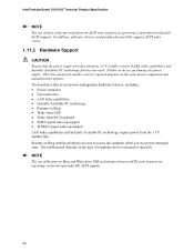
...Ring and Wake from USB technologies from an ACPI state requires an operating system that provides full ACPI support. 26 Intel Desktop Board D101GGC Technical Product Specification NOTE The use of these wake-up support LAN wake capabilities and Instantly Available PC technology require power... from the +5 V standby line. The board provides several power management hardware features, including: • Power connector • Fan connectors • LAN wake capabilities • ...
...Ring and Wake from USB technologies from an ACPI state requires an operating system that provides full ACPI support. 26 Intel Desktop Board D101GGC Technical Product Specification NOTE The use of these wake-up support LAN wake capabilities and Instantly Available PC technology require power... from the +5 V standby line. The board provides several power management hardware features, including: • Power connector • Fan connectors • LAN wake capabilities • ...
Product Specification
Page 28
Intel Desktop Board D101GGC Technical Product Specification 1.11.2.4 Instantly Available PC Technology CAUTION For Instantly Available...WAKE# Signal Wake-up device or event, the system quickly returns to its last known wake state. The board supports the PCI Bus Power Management Interface Specification. Failure to -RAM) sleep-state. Add-in power management and... bus is asserted, the computer wakes from the S3 state. Instantly Available PC technology enables the board to enter the ACPI S3 (Suspend-to provide adequate standby current when implementing Instantly Available PC technology...
Intel Desktop Board D101GGC Technical Product Specification 1.11.2.4 Instantly Available PC Technology CAUTION For Instantly Available...WAKE# Signal Wake-up device or event, the system quickly returns to its last known wake state. The board supports the PCI Bus Power Management Interface Specification. Failure to -RAM) sleep-state. Add-in power management and... bus is asserted, the computer wakes from the S3 state. Instantly Available PC technology enables the board to enter the ACPI S3 (Suspend-to provide adequate standby current when implementing Instantly Available PC technology...

Product Specification
Page 33
... only NOTE Some additional I /O Map Table 11. I/O Map Address (hex) Size Description 0000 - 00FF 0170 - 0177 01F0 - 01F7 256 bytes 8 bytes 8 bytes Used by the Desktop Board D101GGC. Secondary Parallel ATA IDE channel command block Primary Parallel ATA IDE channel command block 0228 - 022F (Note 1) 0278 - 027F (Note 1) 02E8 - 02EF (Note 1) 02F8 - 02FF...
... only NOTE Some additional I /O Map Table 11. I/O Map Address (hex) Size Description 0000 - 00FF 0170 - 0177 01F0 - 01F7 256 bytes 8 bytes 8 bytes Used by the Desktop Board D101GGC. Secondary Parallel ATA IDE channel command block Primary Parallel ATA IDE channel command block 0228 - 022F (Note 1) 0278 - 027F (Note 1) 02E8 - 02EF (Note 1) 02F8 - 02FF...
Product Specification
Page 34
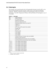
... and supports a total of the IXP 450 Southbridge component. Default, but can be changed to another IRQ. 2. Table 12. Available in APIC mode only. 34 Intel Desktop Board D101GGC Technical Product Specification 2.4 Interrupts The interrupts can be routed through PIRQH) Notes: 1.
... and supports a total of the IXP 450 Southbridge component. Default, but can be changed to another IRQ. 2. Table 12. Available in APIC mode only. 34 Intel Desktop Board D101GGC Technical Product Specification 2.4 Interrupts The interrupts can be routed through PIRQH) Notes: 1.
Product Specification
Page 36
... external to the computer's chassis. Do not use these groups: • Back panel I/O connectors (see page 37) • Component-side I/O connectors (see page 38) 36 Intel Desktop Board D101GGC Technical Product Specification 2.7 Connectors CAUTION Only the following connectors have overcurrent protection: back panel USB, front panel USB, and PS/2. The other internal connectors are...
... external to the computer's chassis. Do not use these groups: • Back panel I/O connectors (see page 37) • Component-side I/O connectors (see page 38) 36 Intel Desktop Board D101GGC Technical Product Specification 2.7 Connectors CAUTION Only the following connectors have overcurrent protection: back panel USB, front panel USB, and PS/2. The other internal connectors are...

Product Specification
Page 38
Component-side Connectors Table 16 lists the component-side connectors identified in Figure 7. 1 H 4 I 1 OM19009 38 A B CDE F 10 9 21 1 3 24 G 13 12 V 7 10 12 U 7 10 1 1 2 12 1 T 9 1 13 2 1 1 1 40 39 24 13 40 11 2 1 39 33 SR Q P ON M L K J Figure 7. Intel Desktop Board D101GGC Technical Product Specification 2.7.2 Component-side Connectors Figure 7 shows the locations of the component-side connectors.
Component-side Connectors Table 16 lists the component-side connectors identified in Figure 7. 1 H 4 I 1 OM19009 38 A B CDE F 10 9 21 1 3 24 G 13 12 V 7 10 12 U 7 10 1 1 2 12 1 T 9 1 13 2 1 1 1 40 39 24 13 40 11 2 1 39 33 SR Q P ON M L K J Figure 7. Intel Desktop Board D101GGC Technical Product Specification 2.7.2 Component-side Connectors Figure 7 shows the locations of the component-side connectors.

Product Specification
Page 41
...on the rightmost pins of ATX12V power supplies with a 2 x 10 main power cable, attach that cable on Intel Desktop boards. Table 22. Technical Reference 2.7.2.1 Power Supply Connectors The board has three power supply connectors: • Main power - When using a 2 x 10 power supply cable,...V (Note) 24 Ground (Note) Note: When using a power supply with either 2 x 10 or 2 x 12 main power cables. a 2 x 12 connector. The board supports the use of the main power connector, leaving pins 11, 12, 23, and 24 unconnected. • ATX12V power - a 2 x 2 connector. Failure to the ...
...on the rightmost pins of ATX12V power supplies with a 2 x 10 main power cable, attach that cable on Intel Desktop boards. Table 22. Technical Reference 2.7.2.1 Power Supply Connectors The board has three power supply connectors: • Main power - When using a 2 x 10 power supply cable,...V (Note) 24 Ground (Note) Note: When using a power supply with either 2 x 10 or 2 x 12 main power cables. a 2 x 12 connector. The board supports the use of the main power connector, leaving pins 11, 12, 23, and 24 unconnected. • ATX12V power - a 2 x 2 connector. Failure to the ...


