
Product Specification
Page 5
... Summary 10 1.1.2 Block Diagram 11 1.1.3 Board Layout 12 1.2 Online Support ...14 1.3 Processor ...14 1.4 System Memory ...15 1.5 ATI Radeon* Xpress 200 Chipset 16 1.5.1 Graphics Subsystem 16 1.5.2 Firmware Hub (FWH 16 1.5.3 USB ...16 1.5.4 IDE Support 17 1.5.5 Real-Time Clock, CMOS SRAM, and Battery 18 1.6 PCI...1.10.1 Fan Monitoring 23 1.10.2 Chassis Intrusion and Detection 23 1.11 Power Management ...23 1.11.1 ACPI ...24 1.11.2 Hardware Support 26 2 Technical Reference 2.1 Memory Map ...31 2.2 DMA Channels ...32 2.3 Fixed I/O Map...33 2.4 Interrupts ...34 2.5 PCI Configuration ...
... Summary 10 1.1.2 Block Diagram 11 1.1.3 Board Layout 12 1.2 Online Support ...14 1.3 Processor ...14 1.4 System Memory ...15 1.5 ATI Radeon* Xpress 200 Chipset 16 1.5.1 Graphics Subsystem 16 1.5.2 Firmware Hub (FWH 16 1.5.3 USB ...16 1.5.4 IDE Support 17 1.5.5 Real-Time Clock, CMOS SRAM, and Battery 18 1.6 PCI...1.10.1 Fan Monitoring 23 1.10.2 Chassis Intrusion and Detection 23 1.11 Power Management ...23 1.11.1 ACPI ...24 1.11.2 Hardware Support 26 2 Technical Reference 2.1 Memory Map ...31 2.2 DMA Channels ...32 2.3 Fixed I/O Map...33 2.4 Interrupts ...34 2.5 PCI Configuration ...

Product Specification
Page 7
... 11. States for a Two-Color Power LED 43 28. Localized High Temperature Zones 51 Tables 1. Supported System Bus Frequency and Memory Speed Combinations 15 4. Wake-up Devices and Events 25 9. PCI Interrupt Routing Map 35 15. Processor Fan Connector 40 21. Contents Figures 1. System Memory Map 31 10. PCI Configuration Space Map...
... 11. States for a Two-Color Power LED 43 28. Localized High Temperature Zones 51 Tables 1. Supported System Bus Frequency and Memory Speed Combinations 15 4. Wake-up Devices and Events 25 9. PCI Interrupt Routing Map 35 15. Processor Fan Connector 40 21. Contents Figures 1. System Memory Map 31 10. PCI Configuration Space Map...
Product Specification
Page 9
1 Product Description What This Chapter Contains 1.1 Overview ...10 1.2 Online Support ...14 1.3 Processor ...14 1.4 System Memory ...15 1.5 ATI Radeon* Xpress 200 Chipset 16 1.6 PCI Express* Connectors 18 1.7 Legacy I/O Controller 19 1.8 High Definition Audio Subsystem 20 1.9 LAN Subsystem ...22 1.10 Hardware Management Subsystem 23 1.11 Power Management ...23 9
1 Product Description What This Chapter Contains 1.1 Overview ...10 1.2 Online Support ...14 1.3 Processor ...14 1.4 System Memory ...15 1.5 ATI Radeon* Xpress 200 Chipset 16 1.6 PCI Express* Connectors 18 1.7 Legacy I/O Controller 19 1.8 High Definition Audio Subsystem 20 1.9 LAN Subsystem ...22 1.10 Hardware Management Subsystem 23 1.11 Power Management ...23 9
Product Specification
Page 10
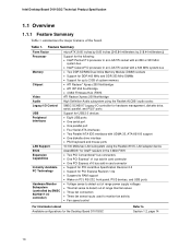
... For information about Available configurations for the Desktop Board D101GGC Refer to detect out of the board. Feature Summary Form Factor Processor Memory Chipset Video Audio Legacy I/O Control USB Peripheral Interfaces LAN Support BIOS Expansion Capabilities Instantly Available PC Technology Hardware Monitor Subsystem...60 inches [243.84 millimeters by 218.44 millimeters]) Support for the following: • Intel® Pentium® 4 processor in an LGA775 socket with an 800 or 533 MHz system bus • Intel® Celeron® D processor in an LGA775 socket with a 533 MHz system bus...
... For information about Available configurations for the Desktop Board D101GGC Refer to detect out of the board. Feature Summary Form Factor Processor Memory Chipset Video Audio Legacy I/O Control USB Peripheral Interfaces LAN Support BIOS Expansion Capabilities Instantly Available PC Technology Hardware Monitor Subsystem...60 inches [243.84 millimeters by 218.44 millimeters]) Support for the following: • Intel® Pentium® 4 processor in an LGA775 socket with an 800 or 533 MHz system bus • Intel® Celeron® D processor in an LGA775 socket with a 533 MHz system bus...
Product Specification
Page 14
Intel Desktop Board D101GGC Technical Product Specification 1.2 Online Support To find information about ... Intel Desktop Board D101GGC under "Desktop Board Products" or "Desktop Board Support" Available configurations for the Desktop Board D101GGC Processor data sheets Audio software and utilities Visit this World Wide Web site: http://www.intel.com/design/motherbd http://support.intel.com/support/motherboards/desktop http://developer.intel.com/design/motherbd...
Intel Desktop Board D101GGC Technical Product Specification 1.2 Online Support To find information about ... Intel Desktop Board D101GGC under "Desktop Board Products" or "Desktop Board Support" Available configurations for the Desktop Board D101GGC Processor data sheets Audio software and utilities Visit this World Wide Web site: http://www.intel.com/design/motherbd http://support.intel.com/support/motherboards/desktop http://developer.intel.com/design/motherbd...
Product Specification
Page 15
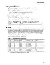
The processor's system bus frequency must be impacted or the DIMMs may be ... Table 4 lists the supported DIMM configurations. Table 4. Product Description 1.4 System Memory The board has two DIMM sockets and supports the following memory features: • 2.5 V (only) DDR SDRAM DIMMs • Unbuffered, single-sided ...Non-ECC DIMMs • Serial Presence Detect • DDR 400 MHz and DDR 333 MHz SDRAM DIMMs Table 3 lists the supported system bus frequency and memory speed combinations. If non-SPD memory is installed, the BIOS will attempt to accurately configure memory settings ...
The processor's system bus frequency must be impacted or the DIMMs may be ... Table 4 lists the supported DIMM configurations. Table 4. Product Description 1.4 System Memory The board has two DIMM sockets and supports the following memory features: • 2.5 V (only) DDR SDRAM DIMMs • Unbuffered, single-sided ...Non-ECC DIMMs • Serial Presence Detect • DDR 400 MHz and DDR 333 MHz SDRAM DIMMs Table 3 lists the supported system bus frequency and memory speed combinations. If non-SPD memory is installed, the BIOS will attempt to accurately configure memory settings ...
Product Specification
Page 16
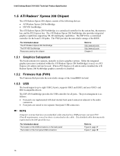
...Firmware Hub provides the nonvolatile storage of the AwardBIOS for Intel. 1.5.3 USB The board supports up to the cable. Intel Desktop Board D101GGC Technical Product Specification 1.5 ATI Radeon* Xpress 200 Chipset... The ATI Radeon Xpress 200 chipset consists of the following devices: • ATI Radeon Xpress 200 Northbridge • IXP 450 Southbridge The ATI Radeon Xpress 200 Northbridge is a centralized controller for the board's I/O paths. Either the integrated graphics processor...
...Firmware Hub provides the nonvolatile storage of the AwardBIOS for Intel. 1.5.3 USB The board supports up to the cable. Intel Desktop Board D101GGC Technical Product Specification 1.5 ATI Radeon* Xpress 200 Chipset... The ATI Radeon Xpress 200 chipset consists of the following devices: • ATI Radeon Xpress 200 Northbridge • IXP 450 Southbridge The ATI Radeon Xpress 200 Northbridge is a centralized controller for the board's I/O paths. Either the integrated graphics processor...
Product Specification
Page 17
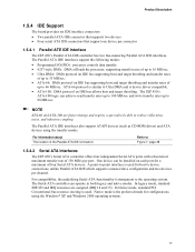
...noise, and inductive coupling. NOTE ATA-66 and ATA-100 are assigned (IRQ 14 and 15). In legacy mode, standard IDE I /O (PIO): processor controls data transfer. • 8237-style DMA: DMA offloads the processor, supporting transfer rates of up to 16 MB/sec. • Ultra DMA: DMA protocol on IDE bus... supporting host and target throttling and transfer rates of up to 33 MB/sec. • ATA-66: DMA protocol on IDE bus supporting host and target throttling and ...
...noise, and inductive coupling. NOTE ATA-66 and ATA-100 are assigned (IRQ 14 and 15). In legacy mode, standard IDE I /O (PIO): processor controls data transfer. • 8237-style DMA: DMA offloads the processor, supporting transfer rates of up to 16 MB/sec. • Ultra DMA: DMA protocol on IDE bus... supporting host and target throttling and transfer rates of up to 33 MB/sec. • ATA-66: DMA protocol on IDE bus supporting host and target throttling and ...

Product Specification
Page 23
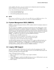
...ambient temperature sensor • Two remote thermal diode sensors for direct monitoring of processor temperature and ambient temperature sensing • Power supply monitoring of the SMSC ...Refer to Section 1.11.2.2, page 27 1.10.2 Chassis Intrusion and Detection The board supports a chassis security feature that attaches to detect levels above or below acceptable values &#... For information about The functions of the chassis intrusion connector Refer to be implemented using Intel® Desktop Utilities, LANDesk* software, or thirdparty software. Product Description 1.10 Hardware ...
...ambient temperature sensor • Two remote thermal diode sensors for direct monitoring of processor temperature and ambient temperature sensing • Power supply monitoring of the SMSC ...Refer to Section 1.11.2.2, page 27 1.10.2 Chassis Intrusion and Detection The board supports a chassis security feature that attaches to detect levels above or below acceptable values &#... For information about The functions of the chassis intrusion connector Refer to be implemented using Intel® Desktop Utilities, LANDesk* software, or thirdparty software. Product Description 1.10 Hardware ...
Product Specification
Page 27
...• The onboard LAN subsystem 27 LAN wake capabilities enable remote wake-up the computer. For information about The signal names of the processor fan connector The signal names of the chassis fan connectors Refer to a fan tachometer input of the SMSC SCH5017 I/O controller. • All fan...Independent Interface. Depending on when the board is in the S0 or S1 state. • The fans are on the LAN implementation, the board supports LAN wake capabilities with ACPI in the following ways: • The PCI Express WAKE# signal • The PCI Conventional bus PME# signal ...
...• The onboard LAN subsystem 27 LAN wake capabilities enable remote wake-up the computer. For information about The signal names of the processor fan connector The signal names of the chassis fan connectors Refer to a fan tachometer input of the SMSC SCH5017 I/O controller. • All fan...Independent Interface. Depending on when the board is in the S0 or S1 state. • The fans are on the LAN implementation, the board supports LAN wake capabilities with ACPI in the following ways: • The PCI Express WAKE# signal • The PCI Conventional bus PME# signal ...

Product Specification
Page 41
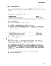
This connector provides power directly to do so will be used on Intel Desktop boards. Table 23. The board supports the use of the main power connector, leaving pins 11, 12, 23, and 24 unconnected. • ATX12V power - Main Power Connector Pin Signal...10 connectors previously used . ATX12V Power Connector Pin Signal Name 1 Ground 3 +12 V Pin Signal Name 2 Ground 4 +12 V 41 Failure to the processor voltage regulator and must always be unconnected. Table 22. a 2 x 12 connector. a 2 x 2 connector. Technical Reference 2.7.2.1 Power Supply Connectors The ...
This connector provides power directly to do so will be used on Intel Desktop boards. Table 23. The board supports the use of the main power connector, leaving pins 11, 12, 23, and 24 unconnected. • ATX12V power - Main Power Connector Pin Signal...10 connectors previously used . ATX12V Power Connector Pin Signal Name 1 Ground 3 +12 V Pin Signal Name 2 Ground 4 +12 V 41 Failure to the processor voltage regulator and must always be unconnected. Table 22. a 2 x 12 connector. a 2 x 2 connector. Technical Reference 2.7.2.1 Power Supply Connectors The ...

Product Specification
Page 49
...by the integrator. The power supply must be connected to the processor fan connector, not to a chassis fan connector may result in onboard component damage that will depend on the wake devices supported and manufacturing options. Additional power required will halt fan operation. ...Connecting the processor fan to a chassis fan connector. System integrators should refer to do so can damage the...
...by the integrator. The power supply must be connected to the processor fan connector, not to a chassis fan connector may result in onboard component damage that will depend on the wake devices supported and manufacturing options. Additional power required will halt fan operation. ...Connecting the processor fan to a chassis fan connector. System integrators should refer to do so can damage the...
Product Specification
Page 62
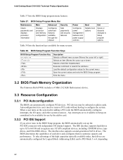
...user turns on the system after adding a PCI card, the BIOS automatically configures interrupts, the I /O channel support. Intel Desktop Board D101GGC Technical Product Specification Table 37 lists the BIOS Setup program menu features. Table 38. Any interrupts set to Available...resources. The interface also supports second-generation SATA drives. PCI devices may be available for menu screens. Table 37. BIOS Setup Program Menu Bar Maintenance Main Advanced Security Clears passwords and displays processor information Displays processor and memory configuration Configures advanced...
...user turns on the system after adding a PCI card, the BIOS automatically configures interrupts, the I /O channel support. Intel Desktop Board D101GGC Technical Product Specification Table 37 lists the BIOS Setup program menu features. Table 38. Any interrupts set to Available...resources. The interface also supports second-generation SATA drives. PCI devices may be available for menu screens. Table 37. BIOS Setup Program Menu Bar Maintenance Main Advanced Security Clears passwords and displays processor information Displays processor and memory configuration Configures advanced...
Product Specification
Page 63
... Fixed-system data, such as peripherals, serial numbers, and asset tags • Resource data, such as memory size, cache size, and processor speed • Dynamic data, such as event detection and error logging Non-Plug and Play operating systems, such as Windows NT*, require an ... system can obtain the system types, capabilities, operational status, and installation dates for managing computers in the BIOS Setup program. Legacy USB support is enabled by specifying manual configuration in a managed network. The BIOS stores and reports the following items are not yet available. POST ...
... Fixed-system data, such as peripherals, serial numbers, and asset tags • Resource data, such as memory size, cache size, and processor speed • Dynamic data, such as event detection and error logging Non-Plug and Play operating systems, such as Windows NT*, require an ... system can obtain the system types, capabilities, operational status, and installation dates for managing computers in the BIOS Setup program. Legacy USB support is enabled by specifying manual configuration in a managed network. The BIOS stores and reports the following items are not yet available. POST ...

Product Specification
Page 72
...Play devices. 2. Early ISA Plug and Play initialization; AWDFLASH is supported. - Display Plug and Play logo 2. Set up floppy related fields in floppy drive. - Assign resources to all extended memory to continue, clear EPA or customization logo. Intel Desktop Board D101GGC Technical Product Specification Table 42. Port 80h POST Codes (continued)...IDE devices: hard disk drive, LS-120 drive, ZIP drive , CD-ROM drive Detect serial port and parallel port Detect and install co-processor Switch back to every ISA Plug and Play device. If errors occur, report errors and wait for keys -
...Play devices. 2. Early ISA Plug and Play initialization; AWDFLASH is supported. - Display Plug and Play logo 2. Set up floppy related fields in floppy drive. - Assign resources to all extended memory to continue, clear EPA or customization logo. Intel Desktop Board D101GGC Technical Product Specification Table 42. Port 80h POST Codes (continued)...IDE devices: hard disk drive, LS-120 drive, ZIP drive , CD-ROM drive Detect serial port and parallel port Detect and install co-processor Switch back to every ISA Plug and Play device. If errors occur, report errors and wait for keys -

Intel Desktop Board D101GGC Product Guide English
Page 5
... Supported Operating Systems 10 Desktop Board Components 11 Processor...13 Main Memory ...13 ATI RADEON* XPRESS 200 Chipset 14 Graphics Subsystem ...14 Audio Subsystem ...14 Input/Output (I/O) Controller 15 LAN Subsystem ...15 LAN Subsystem Software 15 RJ-45 LAN Connector LEDs 15 Hi-Speed USB 2.0 Support 16......19 Suspend to RAM (Instantly Available PC Technology 19 Wake from USB...20 Wake from PS/2 Keyboard/Mouse 20 PME# Wakeup Support 20 Speaker...21 Battery...21 Real-Time Clock...21 2 Installing and Replacing Desktop Board Components Before You Begin ...23 Installation Precautions ...
... Supported Operating Systems 10 Desktop Board Components 11 Processor...13 Main Memory ...13 ATI RADEON* XPRESS 200 Chipset 14 Graphics Subsystem ...14 Audio Subsystem ...14 Input/Output (I/O) Controller 15 LAN Subsystem ...15 LAN Subsystem Software 15 RJ-45 LAN Connector LEDs 15 Hi-Speed USB 2.0 Support 16......19 Suspend to RAM (Instantly Available PC Technology 19 Wake from USB...20 Wake from PS/2 Keyboard/Mouse 20 PME# Wakeup Support 20 Speaker...21 Battery...21 Real-Time Clock...21 2 Installing and Replacing Desktop Board Components Before You Begin ...23 Installation Precautions ...
Intel Desktop Board D101GGC Product Guide English
Page 9
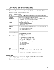
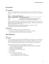
... Related Links: For more information about desktop board D101GGC, including the Technical Product Specification (TPS), BIOS updates, and device drivers, go to: http://support.intel.com/support/motherboards/desktop/ 9 Table 1 summarizes the major ...processor in the LGA775 package Main Memory • Two 184-pin, 2.5 V SDRAM Dual Inline Memory Module (DIMM) sockets • 400/333 MHz single channel DDR SDRAM interface • Designed to support up to 2 GB of the desktop board. 1 Desktop Board Features This chapter briefly describes the main features of Intel® Desktop Board D101GGC...
... Related Links: For more information about desktop board D101GGC, including the Technical Product Specification (TPS), BIOS updates, and device drivers, go to: http://support.intel.com/support/motherboards/desktop/ 9 Table 1 summarizes the major ...processor in the LGA775 package Main Memory • Two 184-pin, 2.5 V SDRAM Dual Inline Memory Module (DIMM) sockets • 400/333 MHz single channel DDR SDRAM interface • Designed to support up to 2 GB of the desktop board. 1 Desktop Board Features This chapter briefly describes the main features of Intel® Desktop Board D101GGC...
Intel Desktop Board D101GGC Product Guide English
Page 12
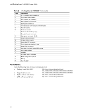
... LED Related Links: Go to the following links for more information about: • Desktop board D101GGC • Supported processors • Audio software and utilities • LAN software and drivers http://www.intel.com/design/motherbd http://support.intel.com/support/motherboards/desktop http://support.intel.com/support/motherboards/desktop http://www.intel.com/design/motherbd http://www.intel.com/design/motherbd 12
... LED Related Links: Go to the following links for more information about: • Desktop board D101GGC • Supported processors • Audio software and utilities • LAN software and drivers http://www.intel.com/design/motherbd http://support.intel.com/support/motherboards/desktop http://support.intel.com/support/motherboards/desktop http://www.intel.com/design/motherbd http://www.intel.com/design/motherbd 12
Intel Desktop Board D101GGC Product Guide English
Page 13
.... The BIOS will see a notification to this effect on the screen at : http://support.intel.com/support/motherboards/desktop/ Related Links: Go to the following links or pages for 10 ms ATX12V (version 2.0 or greater) compliant power supply Desktop board D101GGC supports an Intel processor in Chapter 2 Main Memory NOTE To be fully compliant with DIMMs that...
.... The BIOS will see a notification to this effect on the screen at : http://support.intel.com/support/motherboards/desktop/ Related Links: Go to the following links or pages for 10 ms ATX12V (version 2.0 or greater) compliant power supply Desktop board D101GGC supports an Intel processor in Chapter 2 Main Memory NOTE To be fully compliant with DIMMs that...
Intel Desktop Board D101GGC Product Guide English
Page 17
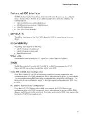
...BIOS Setup program after installing a Serial ATA or IDE device. You can override the auto-configuration options by specifying manual configuration in Chapter 2. The interface supports: • Up to run the BIOS Setup program after you install a PCI/PCI Express add-in card in your computer, the PCI/PCI Express ... devices (such as a hard drive) in your computer. Desktop Board Features Enhanced IDE Interface The IDE interface handles the exchange of information between the processor and peripheral devices like hard disks, CD-ROM drives, and Iomega Zip* drives inside the computer.
...BIOS Setup program after installing a Serial ATA or IDE device. You can override the auto-configuration options by specifying manual configuration in Chapter 2. The interface supports: • Up to run the BIOS Setup program after you install a PCI/PCI Express add-in card in your computer, the PCI/PCI Express ... devices (such as a hard drive) in your computer. Desktop Board Features Enhanced IDE Interface The IDE interface handles the exchange of information between the processor and peripheral devices like hard disks, CD-ROM drives, and Iomega Zip* drives inside the computer.


