
Data Sheet
Page 2
... VMM applications are not a measure of any time, without an Intel 64-enabled BIOS. Check with Intel Turbo Boost Technology capability. Designers must not rely on which processors support HT Technology, see www.intel.com. The Intel® Core™ i7 Processor Extreme Edition and Intel® Core™ i7 Processor may cause the product to deviate from future changes to represent...
... VMM applications are not a measure of any time, without an Intel 64-enabled BIOS. Check with Intel Turbo Boost Technology capability. Designers must not rely on which processors support HT Technology, see www.intel.com. The Intel® Core™ i7 Processor Extreme Edition and Intel® Core™ i7 Processor may cause the product to deviate from future changes to represent...
Data Sheet
Page 3
Contents 1 Introduction ...11 1.1 Terminology ...11 1.1.1 Processor Terminology 11 1.2 References ...13 2 Register Description 15 2.1 Register Terminology 15 2.2 Platform ... SAD_DRAM_RULE_4, SAD_DRAM_RULE_5 SAD_DRAM_RULE_6, SAD_DRAM_RULE_7 46 2.6.7 SAD_INTERLEAVE_LIST_0, SAD_INTERLEAVE_LIST_1 SAD_INTERLEAVE_LIST_2, SAD_INTERLEAVE_LIST_3 SAD_INTERLEAVE_LIST_4, SAD_INTERLEAVE_LIST_5 SAD_INTERLEAVE_LIST_6, SAD_INTERLEAVE_LIST_7 47 2.7 Intel QPI Link Registers 48 2.7.1 QPI_QPILCL_L0, QPI_QPILCL_L1 48 2.8 Integrated Memory Controller Control Registers 48 2.8.1 MC_CONTROL 48 2.8.2...
Contents 1 Introduction ...11 1.1 Terminology ...11 1.1.1 Processor Terminology 11 1.2 References ...13 2 Register Description 15 2.1 Register Terminology 15 2.2 Platform ... SAD_DRAM_RULE_4, SAD_DRAM_RULE_5 SAD_DRAM_RULE_6, SAD_DRAM_RULE_7 46 2.6.7 SAD_INTERLEAVE_LIST_0, SAD_INTERLEAVE_LIST_1 SAD_INTERLEAVE_LIST_2, SAD_INTERLEAVE_LIST_3 SAD_INTERLEAVE_LIST_4, SAD_INTERLEAVE_LIST_5 SAD_INTERLEAVE_LIST_6, SAD_INTERLEAVE_LIST_7 47 2.7 Intel QPI Link Registers 48 2.7.1 QPI_QPILCL_L0, QPI_QPILCL_L1 48 2.8 Integrated Memory Controller Control Registers 48 2.8.1 MC_CONTROL 48 2.8.2...
Data Sheet
Page 8
Tables 1-1 References...13 2-1 Functions Specifically Handled by the Processor 18 2-2 Device 0, Function 0: Generic Non-core Registers 19 2-3 Device 0, Function 1: System Address Decoder Registers 20 2-4 Device 2, Function 0: Intel QPI Link 0 Registers 21 2-5 Device 2, Function 1: Intel QPI Physical 0 Registers 22 2-6 Device 3, Function 0: Integrated Memory Controller Registers 23 2-7 Device 3, Function 1: Target Address Decoder Registers 24 2-8 Device 4, Function 0: Integrated...
Tables 1-1 References...13 2-1 Functions Specifically Handled by the Processor 18 2-2 Device 0, Function 0: Generic Non-core Registers 19 2-3 Device 0, Function 1: System Address Decoder Registers 20 2-4 Device 2, Function 0: Intel QPI Link 0 Registers 21 2-5 Device 2, Function 1: Intel QPI Physical 0 Registers 22 2-6 Device 3, Function 0: Integrated Memory Controller Registers 23 2-7 Device 3, Function 1: Target Address Decoder Registers 24 2-8 Device 4, Function 0: Integrated...
Data Sheet
Page 11
... document the Intel® Core™ i7 processor Extreme Edition and Intel® Core™ i7 processor will be marked as "the processor." Processor features vary by component and include up to two Intel QuickPath Interconnect point to point links capable of up to 6.4 GT/s, up to enable smaller, quieter systems. The Intel® Core™ i7 processor Extreme Edition and Intel® Core™ i7 processor are explained...
... document the Intel® Core™ i7 processor Extreme Edition and Intel® Core™ i7 processor will be marked as "the processor." Processor features vary by component and include up to two Intel QuickPath Interconnect point to point links capable of up to 6.4 GT/s, up to enable smaller, quieter systems. The Intel® Core™ i7 processor Extreme Edition and Intel® Core™ i7 processor are explained...
Data Sheet
Page 12
... and enables more detailed information. Intel VT provides a foundation for Intel® QuickPath Interconnect. • Intel® Virtualization Technology (Intel® VT) - A component of the processor die mounted on the top side of the processor package used to any supply voltages, have any clocks. • Intel® Core™ i7 processor Extreme Edition and Intel® Core™ i7 processor - signals produces a signal eye...
... and enables more detailed information. Intel VT provides a foundation for Intel® QuickPath Interconnect. • Intel® Virtualization Technology (Intel® VT) - A component of the processor die mounted on the top side of the processor package used to any supply voltages, have any clocks. • Intel® Core™ i7 processor Extreme Edition and Intel® Core™ i7 processor - signals produces a signal eye...
Data Sheet
Page 13
... or a falling edge. Table 1-1. References Document Intel® Core™ i7 Processor Extreme Edition and Intel® Core™ i7 Processor Specification Update Intel® Core™ i7 Processor Extreme Edition and Intel® Core™ i7 Processor Datasheet, Volume 1 Intel® Core™ i7 Processor Extreme Edition and Intel® Core™ i7 Processor and LGA1366 Socket Thermal and Mechanical Design Guide Intel® 64 and IA-32 Intel® Architecture Software Developer's Manual •...
... or a falling edge. Table 1-1. References Document Intel® Core™ i7 Processor Extreme Edition and Intel® Core™ i7 Processor Specification Update Intel® Core™ i7 Processor Extreme Edition and Intel® Core™ i7 Processor Datasheet, Volume 1 Intel® Core™ i7 Processor Extreme Edition and Intel® Core™ i7 Processor and LGA1366 Socket Thermal and Mechanical Design Guide Intel® 64 and IA-32 Intel® Architecture Software Developer's Manual •...
Data Sheet
Page 15
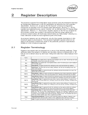
...first write, the bit becomes read or set . This is special case of reading causes the value to this attribute can be written. As processor features vary by component, not all of the field, may be written once. Sticky bits retain their states between hard resets. If a ...bit, a zero must be written to clear this bit, a zero must be read only, the hardware sets its state. In order to all processors. All processor registers appear on a bit by software, but the act of RWL. All multi-byte numeric fields use "little-endian" ordering (i.e., lower addresses ...
...first write, the bit becomes read or set . This is special case of reading causes the value to this attribute can be written. As processor features vary by component, not all of the field, may be written once. Sticky bits retain their states between hard resets. If a ...bit, a zero must be written to clear this bit, a zero must be read only, the hardware sets its state. In order to all processors. All processor registers appear on a bit by software, but the act of RWL. All multi-byte numeric fields use "little-endian" ordering (i.e., lower addresses ...
Data Sheet
Page 16
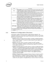
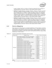
...Note that reserved bits must use appropriate masks to program the processor registers accordingly. Device 4, Function 2 contains the rank registers for Intel QPI Link 0 and resides at DID of the processor registers described in this section contain reserved bits. Device 4,...be cleared by the max bus range setting and processor socket number. • Device 0: Generic processor non-core. Bus number is "sticky" or unchanged by external strapping options. Device 2, Function 0 contains the Intel® QuickPath Interconnect configuration registers for Integrated Memory ...
...Note that reserved bits must use appropriate masks to program the processor registers accordingly. Device 4, Function 2 contains the rank registers for Intel QPI Link 0 and resides at DID of the processor registers described in this section contain reserved bits. Device 4,...be cleared by the max bus range setting and processor socket number. • Device 0: Generic processor non-core. Bus number is "sticky" or unchanged by external strapping options. Device 2, Function 0 contains the Intel® QuickPath Interconnect configuration registers for Integrated Memory ...
Data Sheet
Page 17
... Register Description at DID of 2C29h. Device 5, Function 1 contains the address registers for the processor socket. Device configuration is derived by the Processor Component Register Group Intel QuickPath Architecture Generic Non-core Registers Intel QuickPath Architecture System Address Decoder Intel QPI Link 0 Intel QPI Physical 0 Integrated Memory Controller Registers Integrated Memory Controller Target Address Decoder Integrated Memory...
... Register Description at DID of 2C29h. Device 5, Function 1 contains the address registers for the processor socket. Device configuration is derived by the Processor Component Register Group Intel QuickPath Architecture Generic Non-core Registers Intel QuickPath Architecture System Address Decoder Intel QPI Link 0 Intel QPI Physical 0 Integrated Memory Controller Registers Integrated Memory Controller Target Address Decoder Integrated Memory...
Data Sheet
Page 36
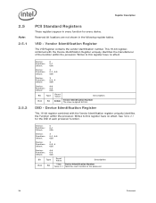
... This 16-bit register, combined with the Vendor Identification register uniquely identifies the Function within the processor. See Table 2-1 for every device. Writes to Intel. DID - Reserved bit locations are not shown in every function for the DID of each ...function of the function within the processor. Device: Function: Offset: 0 0-1 02h Device: Function: Offset: 2 0-1, 4-5 02h Device: Function: Offset: 3 0-2, 4 02h Device: ...
... This 16-bit register, combined with the Vendor Identification register uniquely identifies the Function within the processor. See Table 2-1 for every device. Writes to Intel. DID - Reserved bit locations are not shown in every function for the DID of each ...function of the function within the processor. Device: Function: Offset: 0 0-1 02h Device: Function: Offset: 2 0-1, 4-5 02h Device: Function: Offset: 3 0-2, 4 02h Device: ...
Data Sheet
Page 37
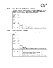
...a specific programming interface (if any), that device independent software can use to the Intel® Core™ i7 Processor Extreme Edition and Intel® Core™ i7 Processor Specification Update for the device. CCR - Class Code Register This register contains the ... function. The Revision ID (RID) is a "Bridge Device". Sub-Class This field qualifies the Base Class, providing a more detailed specification of the processor. Device: Function: Offset: 0 0-1 08h Device: Function: Offset: 2 0-1, 4-5 08h Device: Function: Offset: 3 0-2, 4 08h Device: Function...
...a specific programming interface (if any), that device independent software can use to the Intel® Core™ i7 Processor Extreme Edition and Intel® Core™ i7 Processor Specification Update for the device. CCR - Class Code Register This register contains the ... function. The Revision ID (RID) is a "Bridge Device". Sub-Class This field qualifies the Base Class, providing a more detailed specification of the processor. Device: Function: Offset: 0 0-1 08h Device: Function: Offset: 2 0-1, 4-5 08h Device: Function: Offset: 3 0-2, 4 08h Device: Function...
Data Sheet
Page 38
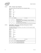
Configuration Layout 0 This field identifies the format of the configuration header layout for devices in the processor. Device: Function: Offset: 0 0-1 0Eh Device: Function: Offset: 2 0-1, 4-5 0Eh Device: Function: Offset: 3 0-2, 4 0Eh Device: Function: Offset: 4-6 0-3 0Eh ...31:16 15:0 Type RWO RWO Reset Value Description Subsystem Identification Number 8086h The default value specifies Intel Vendor Identification Number 8086h The default value specifies Intel. 38 Datasheet Header Type Register This register identifies the header layout of the system. SID/SVID -...
Configuration Layout 0 This field identifies the format of the configuration header layout for devices in the processor. Device: Function: Offset: 0 0-1 0Eh Device: Function: Offset: 2 0-1, 4-5 0Eh Device: Function: Offset: 3 0-2, 4 0Eh Device: Function: Offset: 4-6 0-3 0Eh ...31:16 15:0 Type RWO RWO Reset Value Description Subsystem Identification Number 8086h The default value specifies Intel Vendor Identification Number 8086h The default value specifies Intel. 38 Datasheet Header Type Register This register identifies the header layout of the system. SID/SVID -...
Data Sheet
Page 47
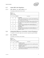
...bit should be set , then the link transmitter is the Primary control register. If this section apply only to processors supporting registered DIMMs. MC_CONTROL This register is an L1 power state slave and should respond to determine if a transmitter...Datasheet 47 Integrated Memory Controller Control Registers The registers in this bit is active. Register Description 2.7 2.7.1 2.8 2.8.1 Intel QPI Link Registers QPI_QPILCL_L0, QPI_QPILCL_L1 This register provides Intel QPI Link Control. Device: 2 Function: 0, 4 Offset: 48h Access as a Dword Bit Type Reset Value ...
...bit should be set , then the link transmitter is the Primary control register. If this section apply only to processors supporting registered DIMMs. MC_CONTROL This register is an L1 power state slave and should respond to determine if a transmitter...Datasheet 47 Integrated Memory Controller Control Registers The registers in this bit is active. Register Description 2.7 2.7.1 2.8 2.8.1 Intel QPI Link Registers QPI_QPILCL_L0, QPI_QPILCL_L1 This register provides Intel QPI Link Control. Device: 2 Function: 0, 4 Offset: 48h Access as a Dword Bit Type Reset Value ...
Data Sheet
Page 63
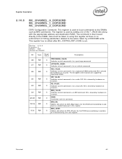
... hardware on issuance. Datasheet 63 Care must be taken in this register as there is cleared by hardware on issuance. MRS_BA. 0 Address bits driven to processors supporting registered DIMMs. WR_VALID. 0 Indicates current command is cleared by hardware on issuance. This bit applies only to DDR_BA[2:0] pins for a registered DIMM config write...
... hardware on issuance. Datasheet 63 Care must be taken in this register as there is cleared by hardware on issuance. MRS_BA. 0 Address bits driven to processors supporting registered DIMMs. WR_VALID. 0 Indicates current command is cleared by hardware on issuance. This bit applies only to DDR_BA[2:0] pins for a registered DIMM config write...
Data Sheet
Page 96
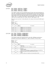
...:24 RO 23:16 RO 15:8 RO 7:0 RO Reset Value Description 0 RANK3. For example when When a rank throttle offset is set , all bits in the processor datasheet (i.e., what an assertion of each rank.
...:24 RO 23:16 RO 15:8 RO 7:0 RO Reset Value Description 0 RANK3. For example when When a rank throttle offset is set , all bits in the processor datasheet (i.e., what an assertion of each rank.
Data Sheet
Page 97
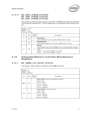
...# is deasserted STATE = 1 means DDR_THERM# is a static indication of the pin, and may be several clocks out of the DDR_THERM# functionality as described in the processor datasheet (i.e., what is happening or has happened with respect to the pin). Value = Qclk 00000 = RSVD 00110 = 800 MHz 01000 = 1066 MHz 01010 = 1333 MHz...
...# is deasserted STATE = 1 means DDR_THERM# is a static indication of the pin, and may be several clocks out of the DDR_THERM# functionality as described in the processor datasheet (i.e., what is happening or has happened with respect to the pin). Value = Qclk 00000 = RSVD 00110 = 800 MHz 01000 = 1066 MHz 01010 = 1333 MHz...

