Data Sheet
Page 2
... will vary depending on whether your hardware and software configurations. Over time processor numbers will not operate (including 32-bit operation) without notice. Enabling Execute Disable Bit functionality requires a PC with a processor with your product order. Intel, Pentium, Intel Core, Intel SpeedStep, and the Intel logo are not a measure of any particular feature. Not all specified units...
... will vary depending on whether your hardware and software configurations. Over time processor numbers will not operate (including 32-bit operation) without notice. Enabling Execute Disable Bit functionality requires a PC with a processor with your product order. Intel, Pentium, Intel Core, Intel SpeedStep, and the Intel logo are not a measure of any particular feature. Not all specified units...
Data Sheet
Page 3
... 2.6.4 Die Voltage Validation 21 2.7 Signaling Specifications 21 2.7.1 FSB Signal Groups 22 2.7.2 CMOS and Open Drain Signals 23 2.7.3 Processor DC Specifications 24 2.7.3.1 Platform Environment Control Interface (PECI) DC Specifications 25 2.7.3.2 GTL+ Front Side Bus Specifications 26 2.8 Clock... Specifications 27 2.8.1 Front Side Bus Clock (BCLK[1:0]) and Processor Clocking 27 2.8.2 FSB Frequency Select Signals (BSEL[2:0 28 2.8.3 Phase Lock Loop (PLL) and Filter 29 2.8.4 BCLK[1:0] Specifications 29...
... 2.6.4 Die Voltage Validation 21 2.7 Signaling Specifications 21 2.7.1 FSB Signal Groups 22 2.7.2 CMOS and Open Drain Signals 23 2.7.3 Processor DC Specifications 24 2.7.3.1 Platform Environment Control Interface (PECI) DC Specifications 25 2.7.3.2 GTL+ Front Side Bus Specifications 26 2.8 Clock... Specifications 27 2.8.1 Front Side Bus Clock (BCLK[1:0]) and Processor Clocking 27 2.8.2 FSB Frequency Select Signals (BSEL[2:0 28 2.8.3 Phase Lock Loop (PLL) and Filter 29 2.8.4 BCLK[1:0] Specifications 29...
Data Sheet
Page 4
... 88 6.2.6 Deep Sleep State 89 6.2.7 Deeper Sleep State 89 6.2.8 Enhanced Intel SpeedStep® Technology 90 6.3 Processor Power Status Indicator (PSI) Signal 90 7 Boxed Processor Specifications 91 7.1 Introduction ...91 7.2 Mechanical Specifications 92 7.2.1 Boxed Processor Cooling Solution Dimensions 92 7.2.2 Boxed Processor Fan Heatsink Weight 93 7.2.3 Boxed Processor Retention Mechanism and Heatsink Attach Clip Assembly 93 7.3 Electrical Requirements 93...
... 88 6.2.6 Deep Sleep State 89 6.2.7 Deeper Sleep State 89 6.2.8 Enhanced Intel SpeedStep® Technology 90 6.3 Processor Power Status Indicator (PSI) Signal 90 7 Boxed Processor Specifications 91 7.1 Introduction ...91 7.2 Mechanical Specifications 92 7.2.1 Boxed Processor Cooling Solution Dimensions 92 7.2.2 Boxed Processor Fan Heatsink Weight 93 7.2.3 Boxed Processor Retention Mechanism and Heatsink Attach Clip Assembly 93 7.3 Electrical Requirements 93...

Data Sheet
Page 5
...31 5 Processor Package Assembly Sketch 33 6 Processor Package Drawing Sheet 1 of 3 34 7 Processor Package Drawing Sheet 2 of 3 35 8 Processor Package Drawing Sheet 3 of the Boxed Processor 91 19 Space Requirements for the Boxed Processor (Side View 92 20 Space Requirements for the Boxed Processor (Top ... 23 Baseboard Power Header Placement Relative to Processor Socket 95 24 Boxed Processor Fan Heatsink Airspace Keepout Requirements (side 1 view 96 25 Boxed Processor Fan Heatsink Airspace Keepout Requirements (side 2 view 96 26 Boxed Processor Fan Heatsink Set Points 97 Datasheet 5...
...31 5 Processor Package Assembly Sketch 33 6 Processor Package Drawing Sheet 1 of 3 34 7 Processor Package Drawing Sheet 2 of 3 35 8 Processor Package Drawing Sheet 3 of the Boxed Processor 91 19 Space Requirements for the Boxed Processor (Side View 92 20 Space Requirements for the Boxed Processor (Top ... 23 Baseboard Power Header Placement Relative to Processor Socket 95 24 Boxed Processor Fan Heatsink Airspace Keepout Requirements (side 1 view 96 25 Boxed Processor Fan Heatsink Airspace Keepout Requirements (side 2 view 96 26 Boxed Processor Fan Heatsink Set Points 97 Datasheet 5...

Data Sheet
Page 6
...1 References ...11 2 Voltage Identification Definition 15 3 Absolute Maximum and Minimum Ratings 17 4 Voltage and Current Specifications 18 5 Processor VCC Static and Transient Tolerance 19 6 VCC Overshoot Specifications 20 7 FSB Signal Groups ...22 8 Signal Characteristics 23 9 Signal... Side Bus Differential BCLK Specifications 29 18 FSB Differential Clock Specifications (800 MHz FSB 30 19 Processor Loading Specifications 37 20 Package Handling Guidelines 37 21 Processor Materials 38 22 Alphabetical Land Assignments 44 23 Numerical Land Assignment 54 24 Signal Description...64 25...
...1 References ...11 2 Voltage Identification Definition 15 3 Absolute Maximum and Minimum Ratings 17 4 Voltage and Current Specifications 18 5 Processor VCC Static and Transient Tolerance 19 6 VCC Overshoot Specifications 20 7 FSB Signal Groups ...22 8 Signal Characteristics 23 9 Signal... Side Bus Differential BCLK Specifications 29 18 FSB Differential Clock Specifications (800 MHz FSB 30 19 Processor Loading Specifications 37 20 Package Handling Guidelines 37 21 Processor Materials 38 22 Alphabetical Land Assignments 44 23 Numerical Land Assignment 54 24 Signal Description...64 25...
Data Sheet
Page 7
... line • Advance Dynamic Execution • Very deep out-of the Intel 64 architecture. Intel® Pentium® Dual-Core Processor E5000 Series Features • Available at 2.66 GHz, 2.50 GHz • Enhanced Intel Speedstep® Technology • Supports Intel® 64Φ architecture • Supports Execute Disable Bit capability • FSB frequency at 800 MHz • Binary...
... line • Advance Dynamic Execution • Very deep out-of the Intel 64 architecture. Intel® Pentium® Dual-Core Processor E5000 Series Features • Available at 2.66 GHz, 2.50 GHz • Enhanced Intel Speedstep® Technology • Supports Intel® 64Φ architecture • Supports Execute Disable Bit capability • FSB frequency at 800 MHz • Binary...
Data Sheet
Page 9
...), Streaming SIMD Extensions 3 (SSE3), and Supplemental Streaming SIMD Extension 3 (SSSE3). In this document, unless otherwise specified, the Intel® Pentium® dual-core processor E5000 series refers to as a "double-clocked" or 2X address bus. In the case of signals where the name does ... but describes part of L2 cache. Datasheet 9 In this document, the Intel® Pentium® dual-core processor E5000 series may be referred to the Intel® Pentium® dual-core processor E5200 and E5300. The processor features an 800 MHz front side bus (FSB) and 2 MB of ...
...), Streaming SIMD Extensions 3 (SSE3), and Supplemental Streaming SIMD Extension 3 (SSSE3). In this document, unless otherwise specified, the Intel® Pentium® dual-core processor E5000 series refers to as a "double-clocked" or 2X address bus. In the case of signals where the name does ... but describes part of L2 cache. Datasheet 9 In this document, the Intel® Pentium® dual-core processor E5000 series may be referred to the Intel® Pentium® dual-core processor E5200 and E5300. The processor features an 800 MHz front side bus (FSB) and 2 MB of ...
Data Sheet
Page 10
...heatsink attach, a retention mechanism is the generic form of the Intel® Pentium® dual-core processor E5000 series. • Voltage Regulator Design Guide - Also referred to : http://www.intel.com/technology/architecture/ coremicro/ • Keep-out zone - For... or receive any mechanical features for clarification: • Intel® Pentium® dual-core processor E5000 series - Processor die with the processor at the IHS surface. • Retention mechanism (RM) - Under these conditions, processor lands should attach to "free air"(i.e., unsealed packaging or ...
...heatsink attach, a retention mechanism is the generic form of the Intel® Pentium® dual-core processor E5000 series. • Voltage Regulator Design Guide - Also referred to : http://www.intel.com/technology/architecture/ coremicro/ • Keep-out zone - For... or receive any mechanical features for clarification: • Intel® Pentium® dual-core processor E5000 series - Processor die with the processor at the IHS surface. • Retention mechanism (RM) - Under these conditions, processor lands should attach to "free air"(i.e., unsealed packaging or ...
Data Sheet
Page 11
... average power consumption (in conjunction with OS support). • Platform Environment Control Interface (PECI) - References Document Location Intel® Pentium® Dual-Core Processor E5000 Series Specification Update Intel® Core™2 Duo processor E8000 and E7000 Series, and Intel® Pentium® Dual-Core Processor E5000 Series Thermal and Mechanical Design Guidelines Voltage Regulator-Down (VRD) 11...
... average power consumption (in conjunction with OS support). • Platform Environment Control Interface (PECI) - References Document Location Intel® Pentium® Dual-Core Processor E5000 Series Specification Update Intel® Core™2 Duo processor E8000 and E7000 Series, and Intel® Pentium® Dual-Core Processor E5000 Series Thermal and Mechanical Design Guidelines Voltage Regulator-Down (VRD) 11...
Data Sheet
Page 13
...series resistance (ESR) to filter high frequency content generated by the front side bus and processor activity. The motherboard must be sized to the processor remains within specifications during longer lasting changes in timing violations or reduced lifetime of transistors ...and high internal clock speeds, the processor is not adequate. Contact your Intel field representative for further information. VTT Decoupling Decoupling must be considered including regulator type, power plane ...
...series resistance (ESR) to filter high frequency content generated by the front side bus and processor activity. The motherboard must be sized to the processor remains within specifications during longer lasting changes in timing violations or reduced lifetime of transistors ...and high internal clock speeds, the processor is not adequate. Contact your Intel field representative for further information. VTT Decoupling Decoupling must be considered including regulator type, power plane ...
Data Sheet
Page 14
...the VID Range values provided in Table 4. Bulk decoupling must be delivered to the Intel® Pentium® dual-core Processor E5000 Series Specification Update for further details on the processor package. The voltage set by the new VID. This will represent a DC ...be calibrated during a power management event (Thermal Monitor 2, Enhanced Intel SpeedStep® technology, or Extended HALT State). Refer to the processor VCC lands (see Chapter 2.6.3 for each processor frequency is defined by the processor during manufacturing such that this table refers to a high voltage ...
...the VID Range values provided in Table 4. Bulk decoupling must be delivered to the Intel® Pentium® dual-core Processor E5000 Series Specification Update for further details on the processor package. The voltage set by the new VID. This will represent a DC ...be calibrated during a power management event (Thermal Monitor 2, Enhanced Intel SpeedStep® technology, or Extended HALT State). Refer to the processor VCC lands (see Chapter 2.6.3 for each processor frequency is defined by the processor during manufacturing such that this table refers to a high voltage ...

Data Sheet
Page 16
...pull-up resistor is 50 Ω, then a value between 40 Ω and 60 Ω should have a resistance value within the processor silicon. Inputs and utilized outputs must be used for TESTHI[12,10:0] lands should be used. cannot be grouped with other TESTHI signals ...individually connected to prevent booting under mismatched power requirement situations. For optimum noise margin, all RESERVED lands. For example, a 130 W TDP processor installed in use pull-up resistor which matches the nominal trace impedance. See Chapter 4 for front side bus signals. For unused GTL+ input...
...pull-up resistor is 50 Ω, then a value between 40 Ω and 60 Ω should have a resistance value within the processor silicon. Inputs and utilized outputs must be used for TESTHI[12,10:0] lands should be used. cannot be grouped with other TESTHI signals ...individually connected to prevent booting under mismatched power requirement situations. For optimum noise margin, all RESERVED lands. For example, a 130 W TDP processor installed in use pull-up resistor which matches the nominal trace impedance. See Chapter 4 for front side bus signals. For unused GTL+ input...
Data Sheet
Page 17
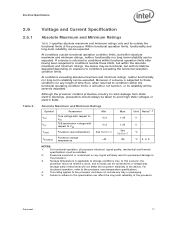
...to conditions within absolute maximum and minimum ratings, neither functionality nor long-term reliability can be expected. For functional operation, all processor electrical, signal quality, mechanical and thermal specifications must not receive a clock, and no lands can be satisfied. 2. This ...rating applies to storage conditions only. Although the processor contains protective circuitry to resist damage from static electric discharge, precautions should always be severely degraded. Storage within these limits, ...
...to conditions within absolute maximum and minimum ratings, neither functionality nor long-term reliability can be expected. For functional operation, all processor electrical, signal quality, mechanical and thermal specifications must not receive a clock, and no lands can be satisfied. 2. This ...rating applies to storage conditions only. Although the processor contains protective circuitry to resist damage from static electric discharge, precautions should always be severely degraded. Storage within these limits, ...
Data Sheet
Page 18
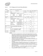
...Min Typ Max Unit Notes2, 10 VID Range VID 0.8500 - 1.3625 V 1 Core VCC Processor Number (2 MB Cache): E5200 E5300 VCC for 775_VR_CONFIG_06: 2.50 GHz 2.66 GHz Refer to any VCC and ICC combination wherein VCC exceeds VCC_MAX for more information. 4. See Section ...4, 5 VCC_BOOT VCCPLL ICC Default VCC voltage for initial power up PLL VCC Processor Number (2 MB Cache): VCC for 775_VR_CONFIG_06: E5200 2.50 GHz E5300 2.66 GHz - - 5% - 1.10 1.50 - + 5% - 75 75 V V A6 FSB termination voltage on Intel 3 series Chipset family boards 1.045 1.1 1.155 VTT (DC + AC ...
...Min Typ Max Unit Notes2, 10 VID Range VID 0.8500 - 1.3625 V 1 Core VCC Processor Number (2 MB Cache): E5200 E5300 VCC for 775_VR_CONFIG_06: 2.50 GHz 2.66 GHz Refer to any VCC and ICC combination wherein VCC exceeds VCC_MAX for more information. 4. See Section ...4, 5 VCC_BOOT VCCPLL ICC Default VCC voltage for initial power up PLL VCC Processor Number (2 MB Cache): VCC for 775_VR_CONFIG_06: E5200 2.50 GHz E5300 2.66 GHz - - 5% - 1.10 1.50 - + 5% - 75 75 V V A6 FSB termination voltage on Intel 3 series Chipset family boards 1.045 1.1 1.155 VTT (DC + AC ...

Data Sheet
Page 19
...table is not tested. 10. Voltage regulation feedback for socket loadline guidelines and VR implementation details. 4. Refer to ensure reliable processor operation. Electrical Specifications Table 5. 7. This is measured at the VCC_SENSE and VSS_SENSE lands. The loadlines specify voltage limits at... the die measured at the land. 8. VTT must be connected to determine the total ITT drawn by only the processor. This specification is the maximum total current drawn from VID Setting (V)1, 2, 3, 4 Maximum Voltage 1.65 mΩ Typical Voltage 1.73 ...
...table is not tested. 10. Voltage regulation feedback for socket loadline guidelines and VR implementation details. 4. Refer to ensure reliable processor operation. Electrical Specifications Table 5. 7. This is measured at the VCC_SENSE and VSS_SENSE lands. The loadlines specify voltage limits at... the die measured at the land. 8. VTT must be connected to determine the total ITT drawn by only the processor. This specification is the maximum total current drawn from VID Setting (V)1, 2, 3, 4 Maximum Voltage 1.65 mΩ Typical Voltage 1.73 ...

Data Sheet
Page 20
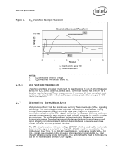
... at the die measured at the VCC_SENSE and VSS_SENSE lands. This overshoot cannot exceed VID + VOS_MAX (VOS_MAX is required to ensure reliable processor operation. 20 Datasheet The time duration of VCC overshoot above VID - 25 µs 2 1 NOTES: 1. Electrical Specifications Figure 1. ...guidelines and VR implementation details. These specifications apply to these specifications is the maximum allowable overshoot voltage). Adherence to the processor die voltage as shown in Section 2.6.3. 2. This loadline specification shows the deviation from a high to the Voltage Regulator...
... at the die measured at the VCC_SENSE and VSS_SENSE lands. This overshoot cannot exceed VID + VOS_MAX (VOS_MAX is required to ensure reliable processor operation. 20 Datasheet The time duration of VCC overshoot above VID - 25 µs 2 1 NOTES: 1. Electrical Specifications Figure 1. ...guidelines and VR implementation details. These specifications apply to these specifications is the maximum allowable overshoot voltage). Adherence to the processor die voltage as shown in Section 2.6.3. 2. This loadline specification shows the deviation from a high to the Voltage Regulator...
Data Sheet
Page 21
... technology. This configuration allows for GTLREF specifications). GTLREF must be generated on the processor silicon and are provided on the motherboard (see Table 14 for improved noise tolerance as VTT. Intel chipsets will also provide on-die termination, thus eliminating the need to determine if... 25 Time [us] TOS: Overshoot time above VID VOS: Overshoot above VID. Die Voltage Validation Overshoot events on the motherboard for each processor (and chipset), separate VCC and VTT supplies are < 10 ns in Table 6 when measured across the VCC_SENSE and VSS_SENSE lands. The GTL...
... technology. This configuration allows for GTLREF specifications). GTLREF must be generated on the processor silicon and are provided on the motherboard (see Table 14 for improved noise tolerance as VTT. Intel chipsets will also provide on-die termination, thus eliminating the need to determine if... 25 Time [us] TOS: Overshoot time above VID VOS: Overshoot above VID. Die Voltage Validation Overshoot events on the motherboard for each processor (and chipset), separate VCC and VTT supplies are < 10 ns in Table 6 when measured across the VCC_SENSE and VSS_SENSE lands. The GTL...

Data Sheet
Page 22
... BCLK[1:0] Synchronous to the GTL+ output group as well as the rising edge of BCLK0. Refer to BCLK[1:0] Clock ADSTB[1:0]#, DSTBP[3:0]#, DSTBN[3:0]# A20M#, DPRSTP#. In processor systems where no connects. 22 Datasheet Similarly, "GTL+ Output" refers to BCLK[1:0] BPRI#, DEFER#, RESET#, RS[2:0]#, TRDY# ADS#, BNR#, BPM[5:0]#, BR0#3, DBSY#, DRDY#, HIT#, HITM...
... BCLK[1:0] Synchronous to the GTL+ output group as well as the rising edge of BCLK0. Refer to BCLK[1:0] Clock ADSTB[1:0]#, DSTBP[3:0]#, DSTBN[3:0]# A20M#, DPRSTP#. In processor systems where no connects. 22 Datasheet Similarly, "GTL+ Output" refers to BCLK[1:0] BPRI#, DEFER#, RESET#, RS[2:0]#, TRDY# ADS#, BNR#, BPM[5:0]#, BR0#3, DBSY#, DRDY#, HIT#, HITM...

Data Sheet
Page 23
... FCx NOTES: 1. Signals that do not have RTT, nor are required to be asserted/deasserted for at least eight BCLKs in order for the processor to their high-voltage level. See Section 2.7.3 for details. 4. Table 8. See Section 6.1 for the DC specifications. Signal Reference Voltages GTLREF BPM...edge of the CMOS and Open Drain signals are actively driven to recognize the proper signal state. All of RESET# defines the processor configuration options. Electrical Specifications . PROCHOT# signal type is open drain output and CMOS input. See Table 11 for entering and ...
... FCx NOTES: 1. Signals that do not have RTT, nor are required to be asserted/deasserted for at least eight BCLKs in order for the processor to their high-voltage level. See Section 2.7.3 for details. 4. Table 8. See Section 6.1 for the DC specifications. Signal Reference Voltages GTLREF BPM...edge of the CMOS and Open Drain signals are actively driven to recognize the proper signal state. All of RESET# defines the processor configuration options. Electrical Specifications . PROCHOT# signal type is open drain output and CMOS input. See Table 11 for entering and ...

Data Sheet
Page 24
...100 µA 6 Output Leakage Current N/A ± 100 µA 7 Buffer On Resistance 7.49 9.16 Ω NOTES: 1. Leakage to all processor frequencies. 2. Measured at a receiving agent that will be interpreted as a logical high value. 4. The VTT referred to in this table apply to ... Table 11. VIH is the instantaneous VTT. 6. VIH and VOH may experience excursions above VTT. 5. Unless otherwise noted, all processor frequencies. 2. GTL+ Signal Group DC Specifications Symbol Parameter Min Max Unit Notes1 VIL VIH VOH IOL ILI ILO RON Input Low ...
...100 µA 6 Output Leakage Current N/A ± 100 µA 7 Buffer On Resistance 7.49 9.16 Ω NOTES: 1. Leakage to all processor frequencies. 2. Measured at a receiving agent that will be interpreted as a logical high value. 4. The VTT referred to in this table apply to ... Table 11. VIH is the instantaneous VTT. 6. VIH and VOH may experience excursions above VTT. 5. Unless otherwise noted, all processor frequencies. 2. GTL+ Signal Group DC Specifications Symbol Parameter Min Max Unit Notes1 VIL VIH VOH IOL ILI ILO RON Input Low ...

