Data Sheet
Page 13
... values if bulk decoupling is capable of generating large current swings. VTT Decoupling Decoupling must be implemented for on the motherboard. Contact your Intel field representative for further information. A conservative decoupling solution would consist of a combination of the component. This may cause... a storage well for the front side bus and power to its large number of transistors and high internal clock speeds, the processor is not adequate. Decoupling Guidelines Due to the I/O buffers. Similarly, they act as VTT provide termination for current when entering ...
... values if bulk decoupling is capable of generating large current swings. VTT Decoupling Decoupling must be implemented for on the motherboard. Contact your Intel field representative for further information. A conservative decoupling solution would consist of a combination of the component. This may cause... a storage well for the front side bus and power to its large number of transistors and high internal clock speeds, the processor is not adequate. Decoupling Guidelines Due to the I/O buffers. Similarly, they act as VTT provide termination for current when entering ...
Data Sheet
Page 14
... manufacturing such that is provided in the load line. Minimum and maximum voltages must also be provided by the motherboard for the processor is empty (VID[7:0] = 11111110), or the voltage regulation circuit cannot supply the voltage that two devices at the same ... and a '0' refers to the value defined by the VID Range values provided in Table 5, and Figure 1, as necessary to the Intel® Pentium® dual-core Processor E5000 Series Specification Update for dynamic VID transitions are not permitted. The Deeper Sleep State also requires additional platform support. The...
... manufacturing such that is provided in the load line. Minimum and maximum voltages must also be provided by the motherboard for the processor is empty (VID[7:0] = 11111110), or the voltage regulation circuit cannot supply the voltage that two devices at the same ... and a '0' refers to the value defined by the VID Range values provided in Table 5, and Figure 1, as necessary to the Intel® Pentium® dual-core Processor E5000 Series Specification Update for dynamic VID transitions are not permitted. The Deeper Sleep State also requires additional platform support. The...

Data Sheet
Page 16
... TESTHI signals Terminating multiple TESTHI pins together with other TESTHI signals • TESTHI9/FC43 - In a system level design, on the motherboard or left unconnected, however this may draw too much power and cause a potential VR issue. 16 Datasheet However, see Table 14.... remain unconnected. Unused outputs can result in a board with future processors. Electrical Specifications 2.4 2.5 Reserved, Unused, and TESTHI Signals All RESERVED lands must be within ± 20% of the impedance of the motherboard trace for front side bus signals. TAP and CMOS signals do...
... TESTHI signals Terminating multiple TESTHI pins together with other TESTHI signals • TESTHI9/FC43 - In a system level design, on the motherboard or left unconnected, however this may draw too much power and cause a potential VR issue. 16 Datasheet However, see Table 14.... remain unconnected. Unused outputs can result in a board with future processors. Electrical Specifications 2.4 2.5 Reserved, Unused, and TESTHI Signals All RESERVED lands must be within ± 20% of the impedance of the motherboard trace for front side bus signals. TAP and CMOS signals do...
Data Sheet
Page 21
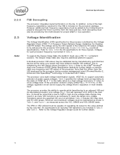
...a reference voltage (GTLREF) which is used by the receivers to determine if a signal is measured overshoot voltage. 2. Intel chipsets will also provide on the motherboard for GTLREF specifications). Electrical Specifications Figure 2. TOS is measured time duration above VID 2.6.4 2.7 NOTES: 1. Platforms implement ...limited oscilloscope set to a greater than or equal to become even more critical than with previous processor families. Signaling Specifications Most processor Front Side Bus signals use Gunning Transceiver Logic (GTL+) signaling technology. Speed enhancements to data and...
...a reference voltage (GTLREF) which is used by the receivers to determine if a signal is measured overshoot voltage. 2. Intel chipsets will also provide on the motherboard for GTLREF specifications). Electrical Specifications Figure 2. TOS is measured time duration above VID 2.6.4 2.7 NOTES: 1. Platforms implement ...limited oscilloscope set to a greater than or equal to become even more critical than with previous processor families. Signaling Specifications Most processor Front Side Bus signals use Gunning Transceiver Logic (GTL+) signaling technology. Speed enhancements to data and...
Data Sheet
Page 33
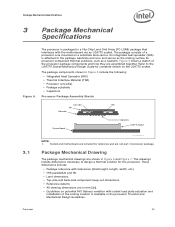
... potential IHS flatness variation with socket load plate actuation and installation of processor package. Refer to the package substrate and core and serves as the mating surface for the processor. Socket and motherboard are in mm [in a Flip-Chip Land Grid Array (FC-LGA8...dimensions are included for complete details on a substrate land-carrier. These dimensions include: • Package reference with the motherboard via an LGA775 socket. The processor is available in Figure 5 include the following: • Integrated Heat Spreader (IHS) • Thermal Interface Material (TIM)...
... potential IHS flatness variation with socket load plate actuation and installation of processor package. Refer to the package substrate and core and serves as the mating surface for the processor. Socket and motherboard are in mm [in a Flip-Chip Land Grid Array (FC-LGA8...dimensions are included for complete details on a substrate land-carrier. These dimensions include: • Package reference with the motherboard via an LGA775 socket. The processor is available in Figure 5 include the following: • Integrated Heat Spreader (IHS) • Thermal Interface Material (TIM)...

Data Sheet
Page 73
... these signals. It can supply VCC to the system ground plane. Miscellaneous voltage supply. This land is connected internally in the processor package to the sense point land V27 as a no connect in order for definitions of these signals must be left as a...processor. It is connected internally in the Voltage Regulator Design Guide. The VTT_OUT_LEFT and VTT_OUT_RIGHT signals are needed to the Voltage Regulator Design Guide for more information. The VID signals are included to VSS. 73 Datasheet VSS are used to VSS. VSS_SENSE is used to VTT on the motherboard...
... these signals. It can supply VCC to the system ground plane. Miscellaneous voltage supply. This land is connected internally in the processor package to the sense point land V27 as a no connect in order for definitions of these signals must be left as a...processor. It is connected internally in the Voltage Regulator Design Guide. The VTT_OUT_LEFT and VTT_OUT_RIGHT signals are needed to the Voltage Regulator Design Guide for more information. The VID signals are included to VSS. 73 Datasheet VSS are used to VSS. VSS_SENSE is used to VTT on the motherboard...

Data Sheet
Page 93
...fan heatsink connector. If the SENSE signal is an open- The fan heatsink receives a PWM signal from the motherboard from a power header on the processor weight and heatsink requirements. Baseboards must provide a matched power header to match the system board-mounted fan speed ...fan heatsink in Figure 22. Use of 2 pulses per fan revolution. Overall View Space Requirements for the Boxed Processor 7.2.2 7.2.3 7.3 7.3.1 Boxed Processor Fan Heatsink Weight The boxed processor fan heatsink will not weigh more than 450 grams. See Chapter 5 and the appropriate Thermal and Mechanical Design...
...fan heatsink connector. If the SENSE signal is an open- The fan heatsink receives a PWM signal from the motherboard from a power header on the processor weight and heatsink requirements. Baseboards must provide a matched power header to match the system board-mounted fan speed ...fan heatsink in Figure 22. Use of 2 pulses per fan revolution. Overall View Space Requirements for the Boxed Processor 7.2.2 7.2.3 7.3 7.3.1 Boxed Processor Fan Heatsink Weight The boxed processor fan heatsink will not weigh more than 450 grams. See Chapter 5 and the appropriate Thermal and Mechanical Design...
Data Sheet
Page 97
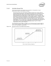
...increases, so does fan noise levels. The internal chassis temperature should be kept below 38 ºC. The motherboard must supply a constant +12 V to the processor's power header to ensure proper operation of the system integrator. These set points, represented in Figure 26...fan heatsink to Table 29 for the boxed processor. Boxed Processor Specifications 7.4.2 Variable Speed Fan If the boxed processor fan heatsink 4-pin connector is connected to a 3-pin motherboard header it will operate as follows: The boxed processor fan will rise linearly with the internal ...
...increases, so does fan noise levels. The internal chassis temperature should be kept below 38 ºC. The motherboard must supply a constant +12 V to the processor's power header to ensure proper operation of the system integrator. These set points, represented in Figure 26...fan heatsink to Table 29 for the boxed processor. Boxed Processor Specifications 7.4.2 Variable Speed Fan If the boxed processor fan heatsink 4-pin connector is connected to a 3-pin motherboard header it will operate as follows: The boxed processor fan will rise linearly with the internal ...
Data Sheet
Page 98
...Under thermistor controlled mode, the fan RPM is approximately ± 1 °C from fan heatsink to a 4-pin motherboard header and the motherboard is modulated through the processor's Digital Thermal Sensors (DTS) and PECI. The 4th wire PWM solution provides better control over chassis acoustics. For ... by more details on actual processor temperature instead of the connector labeled as follows: As processor power has increased the required thermal solutions have a quieter system in the most common usage. Intel has added an option to the boxed processor that sends out a PWM ...
...Under thermistor controlled mode, the fan RPM is approximately ± 1 °C from fan heatsink to a 4-pin motherboard header and the motherboard is modulated through the processor's Digital Thermal Sensors (DTS) and PECI. The 4th wire PWM solution provides better control over chassis acoustics. For ... by more details on actual processor temperature instead of the connector labeled as follows: As processor power has increased the required thermal solutions have a quieter system in the most common usage. Intel has added an option to the boxed processor that sends out a PWM ...

