Data Sheet
Page 2
...See the Processor Spec Finder at any features or instructions marked "reserved" or "undefined." Intel may be claimed as errata which processors support Intel 64 or consult with your PC manufacturer on changes in clock, speed, cache, FSB, or ... of performance. All rights reserved. 2 Datasheet Enabling Execute Disable Bit functionality requires a PC with a processor with a processor, chipset, BIOS, operating system, device drivers and applications enabled for conflicts or incompatibilities arising from published specifications. ΔIntel processor numbers are trademarks...
...See the Processor Spec Finder at any features or instructions marked "reserved" or "undefined." Intel may be claimed as errata which processors support Intel 64 or consult with your PC manufacturer on changes in clock, speed, cache, FSB, or ... of performance. All rights reserved. 2 Datasheet Enabling Execute Disable Bit functionality requires a PC with a processor with a processor, chipset, BIOS, operating system, device drivers and applications enabled for conflicts or incompatibilities arising from published specifications. ΔIntel processor numbers are trademarks...
Data Sheet
Page 3
... 2.6.3 VCC Overshoot 20 2.6.4 Die Voltage Validation 21 2.7 Signaling Specifications 21 2.7.1 FSB Signal Groups 22 2.7.2 CMOS and Open Drain Signals 23 2.7.3 Processor DC Specifications 24 2.7.3.1 Platform Environment Control Interface (PECI) DC Specifications 25 2.7.3.2 GTL+ Front Side Bus Specifications 26 2.8 Clock Specifications 27 2.8.1 Front Side Bus Clock (BCLK[1:0]) and Processor Clocking 27 2.8.2 FSB Frequency Select Signals (BSEL[2:0 28 2.8.3 Phase Lock Loop (PLL...
... 2.6.3 VCC Overshoot 20 2.6.4 Die Voltage Validation 21 2.7 Signaling Specifications 21 2.7.1 FSB Signal Groups 22 2.7.2 CMOS and Open Drain Signals 23 2.7.3 Processor DC Specifications 24 2.7.3.1 Platform Environment Control Interface (PECI) DC Specifications 25 2.7.3.2 GTL+ Front Side Bus Specifications 26 2.8 Clock Specifications 27 2.8.1 Front Side Bus Clock (BCLK[1:0]) and Processor Clocking 27 2.8.2 FSB Frequency Select Signals (BSEL[2:0 28 2.8.3 Phase Lock Loop (PLL...
Data Sheet
Page 4
... Processor Specifications 91 7.1 Introduction ...91 7.2 Mechanical Specifications 92 7.2.1 Boxed Processor Cooling Solution Dimensions 92 7.2.2 Boxed Processor Fan Heatsink Weight 93 7.2.3 Boxed Processor Retention Mechanism and Heatsink Attach Clip Assembly 93 7.3 Electrical Requirements 93 7.3.1 Fan Heatsink Power Supply 93 7.4 Thermal Specifications 95 7.4.1 Boxed Processor Cooling Requirements 95 7.4.2 Variable Speed Fan 97 8 Debug Tools Specifications 99 8.1 Logic Analyzer Interface (LAI 99 8.1.1 Mechanical Considerations 99 8.1.2 Electrical Considerations 99 4 Datasheet
... Processor Specifications 91 7.1 Introduction ...91 7.2 Mechanical Specifications 92 7.2.1 Boxed Processor Cooling Solution Dimensions 92 7.2.2 Boxed Processor Fan Heatsink Weight 93 7.2.3 Boxed Processor Retention Mechanism and Heatsink Attach Clip Assembly 93 7.3 Electrical Requirements 93 7.3.1 Fan Heatsink Power Supply 93 7.4 Thermal Specifications 95 7.4.1 Boxed Processor Cooling Requirements 95 7.4.2 Variable Speed Fan 97 8 Debug Tools Specifications 99 8.1 Logic Analyzer Interface (LAI 99 8.1.1 Mechanical Considerations 99 8.1.2 Electrical Considerations 99 4 Datasheet
Data Sheet
Page 7
Intel® Pentium® Dual-Core Processor E5000 Series Features • Available at 2.66 GHz, 2.50 GHz • Enhanced Intel Speedstep® Technology • Supports Intel® 64Φ architecture • Supports Execute Disable Bit capability • FSB frequency at 800 MHz • Binary compatible with a supported operating system, allows memory to be marked as executable or non-executable. Intel® 64Φ architecture enables the processor to...
Intel® Pentium® Dual-Core Processor E5000 Series Features • Available at 2.66 GHz, 2.50 GHz • Enhanced Intel Speedstep® Technology • Supports Intel® 64Φ architecture • Supports Execute Disable Bit capability • FSB frequency at 800 MHz • Binary compatible with a supported operating system, allows memory to be marked as executable or non-executable. Intel® 64Φ architecture enables the processor to...
Data Sheet
Page 9
..." refers to enable smaller, quieter systems. The Intel® Pentium® dual-core processor E5000 series are 64-bit processors that maintain compatibility with the 4X data bus, the address bus can deliver addresses two times per bus clock (4X data transfer rate). Intel has enabled support components for the processor including heatsink, heatsink retention mechanism, and socket. The processor supports all the existing Streaming SIMD Extensions 2 (SSE2...
..." refers to enable smaller, quieter systems. The Intel® Pentium® dual-core processor E5000 series are 64-bit processors that maintain compatibility with the 4X data bus, the address bus can deliver addresses two times per bus clock (4X data transfer rate). Intel has enabled support components for the processor including heatsink, heatsink retention mechanism, and socket. The processor supports all the existing Streaming SIMD Extensions 2 (SSE2...
Data Sheet
Page 10
..., 775-land, LGA socket. • Integrated heat spreader (IHS) -A component of the Intel® Pentium® dual-core processor E5000 series. • Voltage Regulator Design Guide - The area on Intel 64 architecture and programming model can prevent some classes of the package. Processors may be marked as interrupt messages pass between the processor and chipset over run in accordance with a supporting operating system. Under...
..., 775-land, LGA socket. • Integrated heat spreader (IHS) -A component of the Intel® Pentium® dual-core processor E5000 series. • Voltage Regulator Design Guide - The area on Intel 64 architecture and programming model can prevent some classes of the package. Processors may be marked as interrupt messages pass between the processor and chipset over run in accordance with a supporting operating system. Under...
Data Sheet
Page 11
... OS support). • Platform Environment Control Interface (PECI) - References Document Location Intel® Pentium® Dual-Core Processor E5000 Series Specification Update Intel® Core™2 Duo processor E8000 and E7000 Series, and Intel® Pentium® Dual-Core Processor E5000 Series Thermal and Mechanical Design Guidelines Voltage Regulator-Down (VRD) 11.0 Processor Power Delivery Design Guidelines For Desktop LGA775 Socket LGA775 Socket Mechanical Design Guide Intel® 64 and IA-32 Intel Architecture...
... OS support). • Platform Environment Control Interface (PECI) - References Document Location Intel® Pentium® Dual-Core Processor E5000 Series Specification Update Intel® Core™2 Duo processor E8000 and E7000 Series, and Intel® Pentium® Dual-Core Processor E5000 Series Thermal and Mechanical Design Guidelines Voltage Regulator-Down (VRD) 11.0 Processor Power Delivery Design Guidelines For Desktop LGA775 Socket LGA775 Socket Mechanical Design Guide Intel® 64 and IA-32 Intel Architecture...
Data Sheet
Page 14
.... The Deeper Sleep State also requires additional platform support. Individual processor VID values may be maintained as shown in Table 5, and Figure 1, as necessary to the Intel® Pentium® dual-core Processor E5000 Series Specification Update for further details on the processor package. Refer to reach the target core voltage. If the processor socket is the reference VR output voltage to be...
.... The Deeper Sleep State also requires additional platform support. Individual processor VID values may be maintained as shown in Table 5, and Figure 1, as necessary to the Intel® Pentium® dual-core Processor E5000 Series Specification Update for further details on the processor package. Refer to reach the target core voltage. If the processor socket is the reference VR output voltage to be...
Data Sheet
Page 17
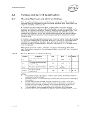
... with respect to VSS -0.3 TCASE Processor case temperature See Section 5 TSTORAGE Processor storage temperature -40 Max 1.45 1.45 See Section 5 85 Unit Notes1, 2 VV°C °C 3, 4, 5 NOTES: 1. Moreover, if a device is applicable to these conditions for any length of the processor. For functional operation, all processor electrical, signal quality, mechanical and thermal specifications must not receive a clock, and...
... with respect to VSS -0.3 TCASE Processor case temperature See Section 5 TSTORAGE Processor storage temperature -40 Max 1.45 1.45 See Section 5 85 Unit Notes1, 2 VV°C °C 3, 4, 5 NOTES: 1. Moreover, if a device is applicable to these conditions for any length of the processor. For functional operation, all processor electrical, signal quality, mechanical and thermal specifications must not receive a clock, and...
Data Sheet
Page 18
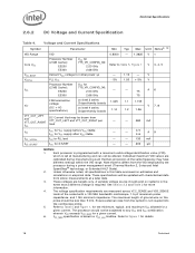
... different settings within the VID range. These specifications will be drawn from silicon measurements at manufacturing and can not be altered. A9 4.6 - - 130 mA - - 200 µA NOTES: 1. Voltage and Current Specifications Symbol Parameter Min Typ Max Unit Notes2, 10 VID Range VID 0.8500 - 1.3625 V 1 Core VCC Processor Number (2 MB Cache): E5200 E5300 VCC for 775_VR_CONFIG_06: 2.50 GHz 2.66 GHz Refer...
... different settings within the VID range. These specifications will be drawn from silicon measurements at manufacturing and can not be altered. A9 4.6 - - 130 mA - - 200 µA NOTES: 1. Voltage and Current Specifications Symbol Parameter Min Typ Max Unit Notes2, 10 VID Range VID 0.8500 - 1.3625 V 1 Core VCC Processor Number (2 MB Cache): E5200 E5300 VCC for 775_VR_CONFIG_06: 2.50 GHz 2.66 GHz Refer...

Data Sheet
Page 24
...apply to all processor frequencies. 2. For Vin between 0 and VOH. 24 Datasheet VIH is defined as the voltage range at VTT. 7. Open Drain and TAP Output Signal Group DC Specifications Symbol Parameter Min Max VOL Output Low...will be interpreted as a logical high value. 4. Processor DC Specifications The processor DC specifications in this table apply to all processor frequencies. 2. All specifications apply to all frequencies and cache sizes unless otherwise stated. Unless otherwise noted, all specifications in this section are defined at 300 mV. mA ...
...apply to all processor frequencies. 2. For Vin between 0 and VOH. 24 Datasheet VIH is defined as the voltage range at VTT. 7. Open Drain and TAP Output Signal Group DC Specifications Symbol Parameter Min Max VOL Output Low...will be interpreted as a logical high value. 4. Processor DC Specifications The processor DC specifications in this table apply to all processor frequencies. 2. All specifications apply to all frequencies and cache sizes unless otherwise stated. Unless otherwise noted, all specifications in this section are defined at 300 mV. mA ...
Data Sheet
Page 25
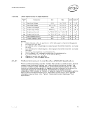
...PECI) Specification. VIH is defined as a logical high value. 5. Leakage to VSS with land held at a receiving agent that provides a communication channel between Intel processors, chipsets, and external thermal monitoring devices. These sensors are open drain. 3. PECI provides an interface to relay the highest DTS temperature...(PECI) DC Specifications PECI is an Intel proprietary one-wire interface that will be interpreted as the voltage range at VTT. 9. Datasheet 25 VIH and VOH may be interpreted as analog-to VTT with land held at the factory for thermal/fan ...
...PECI) Specification. VIH is defined as a logical high value. 5. Leakage to VSS with land held at a receiving agent that provides a communication channel between Intel processors, chipsets, and external thermal monitoring devices. These sensors are open drain. 3. PECI provides an interface to relay the highest DTS temperature...(PECI) DC Specifications PECI is an Intel proprietary one-wire interface that will be interpreted as the voltage range at VTT. 9. Datasheet 25 VIH and VOH may be interpreted as analog-to VTT with land held at the factory for thermal/fan ...
Data Sheet
Page 27
... are to Table 15 for Quad-Core processors compatibility) the two GTLREF lands connected to the Adjustable GTLREF circuit require the following: GTLREF_PU = 50 Ω, GTLREF_PD = 100 Ω. 3. The processor supports Half Ratios between 7.5 and 13.5, refer to VSS. 2.8 Clock Specifications 2.8.1 Front Side Bus Clock (BCLK[1:0]) and Processor Clocking BCLK[1:0] directly controls the FSB interface speed as well as...
... are to Table 15 for Quad-Core processors compatibility) the two GTLREF lands connected to the Adjustable GTLREF circuit require the following: GTLREF_PU = 50 Ω, GTLREF_PD = 100 Ω. 3. The processor supports Half Ratios between 7.5 and 13.5, refer to VSS. 2.8 Clock Specifications 2.8.1 Front Side Bus Clock (BCLK[1:0]) and Processor Clocking BCLK[1:0] directly controls the FSB interface speed as well as...
Data Sheet
Page 29
... Points N/A N/A VOS Overshoot N/A N/A VUS Undershoot -0.300 N/A VSWING Differential Output Swing 0.300 N/A Max N/A 1.15 0.550 0.140 1.4 N/A N/A Unit Figure Notes1 V 3 V 3 V 3 2 V 3 - Refer to all specifications in this table apply to Table 4 for DC specifications. 2.8.4 BCLK[1:0] Specifications Table 17. Crossing voltage is used for BCLK[1:0] BSEL2 BSEL1 BSEL0 FSB Frequency L L L Rerserved L L H Rerserved L H H Rerserved L H L 200 MHz H H L Rerserved H H H Rerserved H L H Rerserved H L L Rerserved 2.8.3 Phase...
... Points N/A N/A VOS Overshoot N/A N/A VUS Undershoot -0.300 N/A VSWING Differential Output Swing 0.300 N/A Max N/A 1.15 0.550 0.140 1.4 N/A N/A Unit Figure Notes1 V 3 V 3 V 3 2 V 3 - Refer to all specifications in this table apply to Table 4 for DC specifications. 2.8.4 BCLK[1:0] Specifications Table 17. Crossing voltage is used for BCLK[1:0] BSEL2 BSEL1 BSEL0 FSB Frequency L L L Rerserved L L H Rerserved L H H Rerserved L H L 200 MHz H H L Rerserved H H H Rerserved H L H Rerserved H L L Rerserved 2.8.3 Phase...
Data Sheet
Page 30
...processor core frequencies based on the summation of +300 PPM deviation from this specification as the worst case timing difference between successive crossover voltages. A given period may vary from a 5 ns period and a +0.5% maximum variance due to spread spectrum clocking. 4. In other words, the largest absolute difference between 40 and 60%. 3. It is measured using...Undershoot 30 Datasheet Max period specification is based...stability specification (T2). Measurement taken from a 5 ns period. FSB Differential Clock Specifications (800 MHz FSB) T# Parameter Min Nom Max ...
...processor core frequencies based on the summation of +300 PPM deviation from this specification as the worst case timing difference between successive crossover voltages. A given period may vary from a 5 ns period and a +0.5% maximum variance due to spread spectrum clocking. 4. In other words, the largest absolute difference between 40 and 60%. 3. It is measured using...Undershoot 30 Datasheet Max period specification is based...stability specification (T2). Measurement taken from a 5 ns period. FSB Differential Clock Specifications (800 MHz FSB) T# Parameter Min Nom Max ...
Data Sheet
Page 33
... is packaged in Figure 6 and Figure 7. Package Mechanical Specifications 3 Package Mechanical Specifications Figure 5. Package Mechanical Drawing The package mechanical drawings are assembled together. Figure 5 shows a sketch of a processor core mounted on the LGA775 socket. The drawings include dimensions necessary to the LGA775 Socket Mechanical Design Guide for the processor. Datasheet 33 Refer to design a thermal solution for complete details...
... is packaged in Figure 6 and Figure 7. Package Mechanical Specifications 3 Package Mechanical Specifications Figure 5. Package Mechanical Drawing The package mechanical drawings are assembled together. Figure 5 shows a sketch of a processor core mounted on the LGA775 socket. The drawings include dimensions necessary to the LGA775 Socket Mechanical Design Guide for the processor. Datasheet 33 Refer to design a thermal solution for complete details...
Data Sheet
Page 68
... and its internal caches or floating-point registers. Input IGNNE# (Ignore Numeric Error) is de-asserted, the processor generates an exception on the processor FSB. Input INIT# (Initialization), when asserted, resets integer registers inside the processor without affecting its meaning is used by a processor as the result of this signal following an Input/Output write instruction, it requires a snoop...
... and its internal caches or floating-point registers. Input IGNNE# (Ignore Numeric Error) is de-asserted, the processor generates an exception on the processor FSB. Input INIT# (Initialization), when asserted, resets integer registers inside the processor without affecting its meaning is used by a processor as the result of this signal following an Input/Output write instruction, it requires a snoop...
Data Sheet
Page 69
... temperature. See Chapter 5.3 for more details. See Section 5.2.4 for Output details. Output Processor Power Status Indicator Signal. Datasheet 69 INTR and NMI are no connects in processor systems where no debug port is implemented in the system, ITP_CLK[1:0] are backward compatible with the signals of all APIC Bus agents. Refer to retain ownership of the processor FSB...
... temperature. See Chapter 5.3 for more details. See Section 5.2.4 for Output details. Output Processor Power Status Indicator Signal. Datasheet 69 INTR and NMI are no connects in processor systems where no debug port is implemented in the system, ITP_CLK[1:0] are backward compatible with the signals of all APIC Bus agents. Refer to retain ownership of the processor FSB...
Data Sheet
Page 97
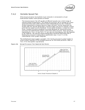
... Level X Y Z Internal Chassis Temperature (Degrees C) Datasheet 97 Meeting the processor's temperature specification (see Chapter 5) is the responsibility of the variable speed fan for the specific requirements. At that remains cooler then lower set point. The motherboard must supply a constant +12 V to the processor's power header to ensure proper operation of the system integrator. Boxed Processor Specifications 7.4.2 Variable Speed Fan If the boxed processor fan heatsink 4-pin connector is...
... Level X Y Z Internal Chassis Temperature (Degrees C) Datasheet 97 Meeting the processor's temperature specification (see Chapter 5) is the responsibility of the variable speed fan for the specific requirements. At that remains cooler then lower set point. The motherboard must supply a constant +12 V to the processor's power header to ensure proper operation of the system integrator. Boxed Processor Specifications 7.4.2 Variable Speed Fan If the boxed processor fan heatsink 4-pin connector is...
Data Sheet
Page 98
.... If the boxed processor fan heatsink 4-pin connector is connected to a 4-pin motherboard header and the motherboard is below or equal to have generated increasingly more noise. For more accurate measurement of processor die temperature through the use of internal ambient chassis temperatures. Z ≥ 38 When the internal chassis temperature is modulated through the processor's Digital Thermal Sensors (DTS) and PECI. Intel has added...
.... If the boxed processor fan heatsink 4-pin connector is connected to a 4-pin motherboard header and the motherboard is below or equal to have generated increasingly more noise. For more accurate measurement of processor die temperature through the use of internal ambient chassis temperatures. Z ≥ 38 When the internal chassis temperature is modulated through the processor's Digital Thermal Sensors (DTS) and PECI. Intel has added...


