
Product Specification
Page 5
... 1.1.1 Feature Summary 12 1.1.2 Manufacturing Options 13 1.1.3 Board Layout 14 1.1.4 Block Diagram 15 1.2 Online Support ...16 1.3 Operating System Support 16 1.4 Design Specifications 17 1.5 Processor ...20 1.6 System Memory ...21 1.6.1 Memory Features 21 1.6.2 Memory Configurations 23 1.7 Intel® 865PE Chipset 28 1.7.1 AGP ...28 1.7.2 USB...29 1.7.3 IDE Support 30 1.7.4 Real-Time Clock, CMOS SRAM, and Battery 31...
... 1.1.1 Feature Summary 12 1.1.2 Manufacturing Options 13 1.1.3 Board Layout 14 1.1.4 Block Diagram 15 1.2 Online Support ...16 1.3 Operating System Support 16 1.4 Design Specifications 17 1.5 Processor ...20 1.6 System Memory ...21 1.6.1 Memory Features 21 1.6.2 Memory Configurations 23 1.7 Intel® 865PE Chipset 28 1.7.1 AGP ...28 1.7.2 USB...29 1.7.3 IDE Support 30 1.7.4 Real-Time Clock, CMOS SRAM, and Battery 31...

Product Specification
Page 6
Intel Desktop Board D865PERL Technical Product Specification 2 Technical Reference 2.1 Introduction...51 2.2 Memory Resources ...51 2.2.1 Addressable Memory 51 2.2.2 Memory Map 53 2.3 DMA Channels ...53 2.4 Fixed I/O Map...54 2.5 PCI Configuration Space Map 55 2.6 Interrupts ....4 Product Ecology Statements 84 2.15.5 Product Certification Markings (Board Level 85 3 Overview of BIOS Features 3.1 Introduction...87 3.2 BIOS Flash Memory Organization 87 3.3 Resource Configuration 88 3.3.1 PCI Autoconfiguration 88 3.3.2 PCI IDE Support 88 3.4 System Management BIOS (SMBIOS 88 3.5 Legacy USB...
Intel Desktop Board D865PERL Technical Product Specification 2 Technical Reference 2.1 Introduction...51 2.2 Memory Resources ...51 2.2.1 Addressable Memory 51 2.2.2 Memory Map 53 2.3 DMA Channels ...53 2.4 Fixed I/O Map...54 2.5 PCI Configuration Space Map 55 2.6 Interrupts ....4 Product Ecology Statements 84 2.15.5 Product Certification Markings (Board Level 85 3 Overview of BIOS Features 3.1 Introduction...87 3.2 BIOS Flash Memory Organization 87 3.3 Resource Configuration 88 3.3.1 PCI Autoconfiguration 88 3.3.2 PCI IDE Support 88 3.4 System Management BIOS (SMBIOS 88 3.5 Legacy USB...

Product Specification
Page 8
Example of Single Channel Configuration without Dynamic Mode 25 6. Intel 865PE Chipset Block Diagram 28 9. Back Panel Connectors for Flex 6 Audio Subsystem 36 12. Back Panel Audio Connector Options for 6-Channel ...Mode 27 8. Thermal Monitoring...42 17. Manufacturing Options 13 3. Effects of the Standby Power Indicator LED 49 18. System Memory Map 53 viii Localized High Temperature Zones 81 Tables 1. Specifications ...17 4. Intel Desktop Board D865PERL Technical Product Specification Figures 1. Desktop Board D865PERL Components 14 2. Block Diagram ...15...
Example of Single Channel Configuration without Dynamic Mode 25 6. Intel 865PE Chipset Block Diagram 28 9. Back Panel Connectors for Flex 6 Audio Subsystem 36 12. Back Panel Audio Connector Options for 6-Channel ...Mode 27 8. Thermal Monitoring...42 17. Manufacturing Options 13 3. Effects of the Standby Power Indicator LED 49 18. System Memory Map 53 viii Localized High Temperature Zones 81 Tables 1. Specifications ...17 4. Intel Desktop Board D865PERL Technical Product Specification Figures 1. Desktop Board D865PERL Components 14 2. Block Diagram ...15...

Product Specification
Page 11
1 Product Description What This Chapter Contains 1.1 Overview ...12 1.2 Online Support ...16 1.3 Operating System Support 16 1.4 Design Specifications 17 1.5 Processor ...20 1.6 System Memory ...21 1.7 Intel® 865PE Chipset 28 1.8 I/O Controller ...32 1.9 IEEE 1394a-2000 Controller (Optional 33 1.10 Audio Subsystem...34 1.11 LAN Subsystem...39 1.12 Hardware Management Subsystem 41 1.13 Power Management 43 11
1 Product Description What This Chapter Contains 1.1 Overview ...12 1.2 Online Support ...16 1.3 Operating System Support 16 1.4 Design Specifications 17 1.5 Processor ...20 1.6 System Memory ...21 1.7 Intel® 865PE Chipset 28 1.8 I/O Controller ...32 1.9 IEEE 1394a-2000 Controller (Optional 33 1.10 Audio Subsystem...34 1.11 LAN Subsystem...39 1.12 Hardware Management Subsystem 41 1.13 Power Management 43 11

Product Specification
Page 12
... system bus • Four 184-pin DDR SDRAM Dual Inline Memory Module (DIMM) sockets • Support for DDR 400, DDR 333, and DDR 266 • Support for up to 4 GB of system memory Intel® 865PE Chipset, consisting of: • Intel® 82865PE Memory Controller Hub (MCH) • Intel® 82801EB I/O Controller Hub (ICH5) or Intel® 82801ER I/O Controller Hub (ICH5-R) •...
... system bus • Four 184-pin DDR SDRAM Dual Inline Memory Module (DIMM) sockets • Support for DDR 400, DDR 333, and DDR 266 • Support for up to 4 GB of system memory Intel® 865PE Chipset, consisting of: • Intel® 82865PE Memory Controller Hub (MCH) • Intel® 82801EB I/O Controller Hub (ICH5) or Intel® 82801ER I/O Controller Hub (ICH5-R) •...

Product Specification
Page 14
...LAN Connect device V Chassis intrusion connector F AGP connector W Serial ATA IDE connectors G Back panel connectors X Speaker H Rear chassis fan Y Intel 82802AB Firmware Hub (FWH) I +12 V power connector (ATX12V) Z BIOS setup configuration jumper J Voltage regulator fan AA Auxiliary front panel ...power LED K mPGA478 processor socket BB Front panel connector L Processor fan connector CC Battery M Intel 82865PE Memory Controller Hub (MCH) DD Front panel USB connectors N DIMM channel A EE IEEE 1394a-2000 front panel connectors (optional) O...
...LAN Connect device V Chassis intrusion connector F AGP connector W Serial ATA IDE connectors G Back panel connectors X Speaker H Rear chassis fan Y Intel 82802AB Firmware Hub (FWH) I +12 V power connector (ATX12V) Z BIOS setup configuration jumper J Voltage regulator fan AA Auxiliary front panel ...power LED K mPGA478 processor socket BB Front panel connector L Processor fan connector CC Battery M Intel 82865PE Memory Controller Hub (MCH) DD Front panel USB connectors N DIMM channel A EE IEEE 1394a-2000 front panel connectors (optional) O...

Product Specification
Page 15
... Hub (MCH) AHA Bus LAN Connector Channel A DIMMs (2) Gigabit LAN PLC (Optional) CSA Interface Dual-Channel Memory Bus SMBus Channel B DIMMs (2) Intel 82801EB (ICH5) or 82801ER (ICH5-R) I/O Controller Hub Intel 82802AB 4 Mbit Firmware Hub (FWH) Intel 865PE Chipset CSMA/CD Unit Interface 10/100 LAN PLC (Optional) LAN Connector AC Link Serial ATA IDE Interface...
... Hub (MCH) AHA Bus LAN Connector Channel A DIMMs (2) Gigabit LAN PLC (Optional) CSA Interface Dual-Channel Memory Bus SMBus Channel B DIMMs (2) Intel 82801EB (ICH5) or 82801ER (ICH5-R) I/O Controller Hub Intel 82802AB 4 Mbit Firmware Hub (FWH) Intel 865PE Chipset CSMA/CD Unit Interface 10/100 LAN PLC (Optional) LAN Connector AC Link Serial ATA IDE Interface...
Product Specification
Page 18
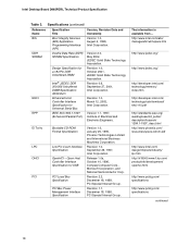
... Date and Ownership Version 1.0, August 4, 1999, Intel Corporation. http://www.intel.com/labs/ manage/wfm/wfmspecs.htm http://www.jedec.org/ http://www.jedec.org/ http://developer.intel.com/ technology/memory/ index.htm http://developer.intel.com/ technology/usb/download/ ehci-r10.pdf http...Title Boot Integrity Services (BIS) Application Programming Interface (API) Double Data Rate (DDR) SDRAM Specification Design Specification for a 184 Pin DDR Unbuffered DIMM Intel ® JEDEC DDR 200/266 Unbuffered DIMM Specification Addendum Enhanced Host Controller Interface Specification for USB PCI ...
... Date and Ownership Version 1.0, August 4, 1999, Intel Corporation. http://www.intel.com/labs/ manage/wfm/wfmspecs.htm http://www.jedec.org/ http://www.jedec.org/ http://developer.intel.com/ technology/memory/ index.htm http://developer.intel.com/ technology/usb/download/ ehci-r10.pdf http...Title Boot Integrity Services (BIS) Application Programming Interface (API) Double Data Rate (DDR) SDRAM Specification Design Specification for a 184 Pin DDR Unbuffered DIMM Intel ® JEDEC DDR 200/266 Unbuffered DIMM Specification Addendum Enhanced Host Controller Interface Specification for USB PCI ...

Product Specification
Page 20
...Section 2.8.2.2, page 63 20 ATX12V power supplies have an additional power lead that provides required supplemental power for important information when using an Intel Pentium 4 processor operating above . The board will not boot. • Do not use a standard ATX power supply. For ...Refer to -date list of supported processors. Supported processors for a list of supported system bus frequency and memory speed combinations. The board is designed to support the following: • Intel Pentium 4 processors in an mPGA478 processor socket with a 400/533/800 MHz system bus •...
...Section 2.8.2.2, page 63 20 ATX12V power supplies have an additional power lead that provides required supplemental power for important information when using an Intel Pentium 4 processor operating above . The board will not boot. • Do not use a standard ATX power supply. For ...Refer to -date list of supported processors. Supported processors for a list of supported system bus frequency and memory speed combinations. The board is designed to support the following: • Intel Pentium 4 processors in an mPGA478 processor socket with a 400/533/800 MHz system bus •...

Product Specification
Page 21
... latencies to optimize system throughput. ✏ NOTES • Remove the AGP video card before installing or upgrading memory to avoid interference with the memory retention mechanism. • To be fully compliant with all applicable DDR SDRAM memory specifications, the board should be populated with x16 organization are not supported. • 4 GB maximum total system...
... latencies to optimize system throughput. ✏ NOTES • Remove the AGP video card before installing or upgrading memory to avoid interference with the memory retention mechanism. • To be fully compliant with all applicable DDR SDRAM memory specifications, the board should be populated with x16 organization are not supported. • 4 GB maximum total system...

Product Specification
Page 22
Supported Memory Configurations DIMM Capacity DDR SDRAM Configuration Density DDR SDRAM Organization Number of DDR Front-side/Back-side SDRAM Devices 64 MB SS 64 Mbit 8 M x 8/empty 8 64 MB SS 128 Mbit 8 M x 16/empty 4 128 MB DS 64 Mbit 8 M... 64 M x 8/64 M x 8 16 Note: In the second column, "DS" refers to double-sided memory modules (containing two rows of DDR SDRAM) and "SS" refers to single-sided memory modules (containing one row of DDR SDRAM). 22 Table 5. Intel Desktop Board D865PERL Technical Product Specification Table 5 lists the supported DIMM configurations.
Supported Memory Configurations DIMM Capacity DDR SDRAM Configuration Density DDR SDRAM Organization Number of DDR Front-side/Back-side SDRAM Devices 64 MB SS 64 Mbit 8 M x 8/empty 8 64 MB SS 128 Mbit 8 M x 16/empty 4 128 MB DS 64 Mbit 8 M... 64 M x 8/64 M x 8 16 Note: In the second column, "DS" refers to double-sided memory modules (containing two rows of DDR SDRAM) and "SS" refers to single-sided memory modules (containing one row of DDR SDRAM). 22 Table 5. Intel Desktop Board D865PERL Technical Product Specification Table 5 lists the supported DIMM configurations.

Product Specification
Page 23
Product Description 1.6.2 Memory Configurations The Intel 82865PE MCH component provides two features for enhancing memory throughput: • Dual Channel memory interface. Table 6. Characteristics of Dynamic Mode. Memory Channel Configuration 23 Dynamic mode minimizes overhead by reducing memory accesses Table 6 summarizes the ...All DIMMs matched (Example configurations are shown in Figure 3 • Dynamic Addressing Mode. The board has two memory channels, each with Dynamic Mode Single DIMM or DIMMs matched within channels (Example configuration is shown in Figure 5) ...
Product Description 1.6.2 Memory Configurations The Intel 82865PE MCH component provides two features for enhancing memory throughput: • Dual Channel memory interface. Table 6. Characteristics of Dynamic Mode. Memory Channel Configuration 23 Dynamic mode minimizes overhead by reducing memory accesses Table 6 summarizes the ...All DIMMs matched (Example configurations are shown in Figure 3 • Dynamic Addressing Mode. The board has two memory channels, each with Dynamic Mode Single DIMM or DIMMs matched within channels (Example configuration is shown in Figure 5) ...

Product Specification
Page 28
...interface. System Bus Parallel ATA IDE Interface CSMA/CD Interface USB 865PE Chipset 82865PE Memory Controller Hub (MCH) AHA Bus 82801EB (ICH5) or 82801ER (ICH5-R) I /O paths. Intel Desktop Board D865PERL Technical Product Specification 1.7 Intel® 865PE Chipset The Intel 865PE chipset consists of the following : • 4x, 8x AGP ... Board D865PERL's I /O Controller Hub 82802AB 4 Mbit Firmware Hub (FWH) CSA Interface AGP Interface Dual-Channel DDR SDRAM Bus Serial LPC Bus ATA IDE SMBus PCI Bus AC Link Interface Figure 8. The ICH5 is independent of the BIOS.
...interface. System Bus Parallel ATA IDE Interface CSMA/CD Interface USB 865PE Chipset 82865PE Memory Controller Hub (MCH) AHA Bus 82801EB (ICH5) or 82801ER (ICH5-R) I /O paths. Intel Desktop Board D865PERL Technical Product Specification 1.7 Intel® 865PE Chipset The Intel 865PE chipset consists of the following : • 4x, 8x AGP ... Board D865PERL's I /O Controller Hub 82802AB 4 Mbit Firmware Hub (FWH) CSA Interface AGP Interface Dual-Channel DDR SDRAM Bus Serial LPC Bus ATA IDE SMBus PCI Bus AC Link Interface Figure 8. The ICH5 is independent of the BIOS.

Product Specification
Page 29
...meets the requirements for full-speed devices. • Native USB 2.0 support has been tested with drivers for other operating system. Check Intel's Desktop Board website for possible driver updates for Windows 2000 (with Service Pack 3) and Windows XP (with stacked back panel connectors...the audio connectors • Four ports are routed to two front panel USB connectors ✏ NOTES • Computer systems that hide memory access latency • Demultiplexing of the AGP connector Obtaining the Accelerated Graphics Port Interface Specification Refer to Figure 1, page 14 Section 1.4, ...
...meets the requirements for full-speed devices. • Native USB 2.0 support has been tested with drivers for other operating system. Check Intel's Desktop Board website for possible driver updates for Windows 2000 (with Service Pack 3) and Windows XP (with stacked back panel connectors...the audio connectors • Four ports are routed to two front panel USB connectors ✏ NOTES • Computer systems that hide memory access latency • Demultiplexing of the AGP connector Obtaining the Accelerated Graphics Port Interface Specification Refer to Figure 1, page 14 Section 1.4, ...

Product Specification
Page 31
... with 3.3 VSB applied. 31 Install the IAA 3.0 RAID driver. 4. For information about Serial ATA Refer to http://www.serialata.org 1.7.3.3 Intel® RAID Technology Boards equipped with the ICH5-R support RAID (Redundant Array of Independent Drives) level 0 on the Serial ATA ports. The...motherbd/rl/index.htm 1.7.4 Real-Time Clock, CMOS SRAM, and Battery A coin-cell battery (CR2032) powers the real-time clock and CMOS memory. Two physical drives, of three years. Format the RAID array. 5. Product Description IDE I/O and IRQ resources are required to successfully establish a...
... with 3.3 VSB applied. 31 Install the IAA 3.0 RAID driver. 4. For information about Serial ATA Refer to http://www.serialata.org 1.7.3.3 Intel® RAID Technology Boards equipped with the ICH5-R support RAID (Redundant Array of Independent Drives) level 0 on the Serial ATA ports. The...motherbd/rl/index.htm 1.7.4 Real-Time Clock, CMOS SRAM, and Battery A coin-cell battery (CR2032) powers the real-time clock and CMOS memory. Two physical drives, of three years. Format the RAID array. 5. Product Description IDE I/O and IRQ resources are required to successfully establish a...

Product Specification
Page 51
... BIOS (firmware hub), and chipset overhead resides above the top of system addresses. 2 Technical Reference What This Chapter Contains 2.1 Introduction...51 2.2 Memory Resources ...51 2.3 DMA Channels ...53 2.4 Fixed I /O map, Table 16 defines the PCI configuration space map, and Table 17 describes the... Considerations 80 2.13 Reliability ...82 2.14 Environmental ...82 2.1 Introduction Sections 2.2 - 2.6 contain several standalone tables. All installed system memory can be used will vary based on a system that can be used when there is set to system address space being allocated for...
... BIOS (firmware hub), and chipset overhead resides above the top of system addresses. 2 Technical Reference What This Chapter Contains 2.1 Introduction...51 2.2 Memory Resources ...51 2.3 DMA Channels ...53 2.4 Fixed I /O map, Table 16 defines the PCI configuration space map, and Table 17 describes the... Considerations 80 2.13 Reliability ...82 2.14 Environmental ...82 2.1 Introduction Sections 2.2 - 2.6 contain several standalone tables. All installed system memory can be used will vary based on a system that can be used when there is set to system address space being allocated for...

Product Specification
Page 52
Intel Desktop Board D865PERL Technical Product Specification memory, AGP aperture set for 256 MB, and the PCI cards are requesting 200 MB of system address space. 4 GB Top of System Address Space FLASH APIC Reserved ~20 MB PCI Memory Range (contains AGP window, AGP aperture, PCI, and ICH ranges) DRAM Range DOS Compatibility Memory... KB) Lower BIOS area (64 KB; 16 KB x 4) Add-in Card BIOS and Buffer area (128 KB; 16 KB x 8) Standard PCI/ ISA Video Memory (SMM Memory) 128 KB * DOS area (640 KB) 1 MB 960 KB 896 KB 768 KB 640 KB 0 KB * Optionally mapped to the internal AGP OM16106 Figure 18...
Intel Desktop Board D865PERL Technical Product Specification memory, AGP aperture set for 256 MB, and the PCI cards are requesting 200 MB of system address space. 4 GB Top of System Address Space FLASH APIC Reserved ~20 MB PCI Memory Range (contains AGP window, AGP aperture, PCI, and ICH ranges) DRAM Range DOS Compatibility Memory... KB) Lower BIOS area (64 KB; 16 KB x 4) Add-in Card BIOS and Buffer area (128 KB; 16 KB x 8) Standard PCI/ ISA Video Memory (SMM Memory) 128 KB * DOS area (640 KB) 1 MB 960 KB 896 KB 768 KB 640 KB 0 KB * Optionally mapped to the internal AGP OM16106 Figure 18...

Product Specification
Page 53
...KB 512 KB Description Extended memory Runtime BIOS Reserved Potential available high DOS memory (open to the PCI bus). Video memory and BIOS Extended BIOS data (movable by memory manager software) Extended conventional memory Conventional memory 2.3 DMA Channels Table 14... C8000 - Dependent on video adapter used. FFFFF 896 K - 960 K E0000 - System Memory Map Address Range (decimal) Address Range (hex) 1024 K - 4194304 K 100000 - Technical Reference 2.2.2 Memory Map Table 13 lists the system memory map. FFFFFFFF 960 K - 1024 K F0000 - DMA Channels DMA Channel Number 0 1 ...
...KB 512 KB Description Extended memory Runtime BIOS Reserved Potential available high DOS memory (open to the PCI bus). Video memory and BIOS Extended BIOS data (movable by memory manager software) Extended conventional memory Conventional memory 2.3 DMA Channels Table 14... C8000 - Dependent on video adapter used. FFFFF 896 K - 960 K E0000 - System Memory Map Address Range (decimal) Address Range (hex) 1024 K - 4194304 K 100000 - Technical Reference 2.2.2 Memory Map Table 13 lists the system memory map. FFFFFFFF 960 K - 1024 K F0000 - DMA Channels DMA Channel Number 0 1 ...

Product Specification
Page 55
... 06 00 01 02 03 07 00 00 00 00 00 00 00 00 00 Description Memory controller of Intel 82865PE component Host to AGP bridge (virtual P2P) PCI to CSA bridge (virtual P2P) Hub link to PCI bridge... Intel 82801EB ICH5 PCI-to-LPC bridge Parallel ATA IDE controller Serial ATA controller SMBus controller AC '97 audio controller... 3 PCI bus connector 4 PCI bus connector 5 IEEE 1394a-2000 controller (optional) Note: Bus number = 03 when the Intel 82547EI Gigabit LAN controller is used. Otherwise, bus number = 02. 55
... 06 00 01 02 03 07 00 00 00 00 00 00 00 00 00 Description Memory controller of Intel 82865PE component Host to AGP bridge (virtual P2P) PCI to CSA bridge (virtual P2P) Hub link to PCI bridge... Intel 82801EB ICH5 PCI-to-LPC bridge Parallel ATA IDE controller Serial ATA controller SMBus controller AC '97 audio controller... 3 PCI bus connector 4 PCI bus connector 5 IEEE 1394a-2000 controller (optional) Note: Bus number = 03 when the Intel 82547EI Gigabit LAN controller is used. Otherwise, bus number = 02. 55

Product Specification
Page 87
The BIOS displays a message during POST identifying the type of BIOS Features What This Chapter Contains 3.1 Introduction...87 3.2 BIOS Flash Memory Organization 87 3.3 Resource Configuration 88 3.4 System Management BIOS (SMBIOS 88 3.5 Legacy USB Support 89 3.6 BIOS Updates ...89 3.7 Recovering BIOS Data 91... if the two match. For information about The Desktop Board's compliance level with Intel® Rapid BIOS Boot 93 3.10 BIOS Security Features 94 3.1 Introduction The Desktop Board uses an Intel/AMI BIOS that is poweredup, the BIOS compares the CPU version and the microcode...
The BIOS displays a message during POST identifying the type of BIOS Features What This Chapter Contains 3.1 Introduction...87 3.2 BIOS Flash Memory Organization 87 3.3 Resource Configuration 88 3.4 System Management BIOS (SMBIOS 88 3.5 Legacy USB Support 89 3.6 BIOS Updates ...89 3.7 Recovering BIOS Data 91... if the two match. For information about The Desktop Board's compliance level with Intel® Rapid BIOS Boot 93 3.10 BIOS Security Features 94 3.1 Introduction The Desktop Board uses an Intel/AMI BIOS that is poweredup, the BIOS compares the CPU version and the microcode...


