Product Specification
Page 6
... 79 3.2 BIOS Flash Memory Organization 80 3.3 Resource Configuration 80 3.3.1 PCI Autoconfiguration 80 3.3.2 PCI IDE Support 81 3.4 System Management BIOS (SMBIOS 81 3.5 Legacy USB Support 82 3.6 BIOS Updates 82 3.6.1 Language Support 83 3.6.2 Custom Splash Screen 83 3.7 BIOS Recovery 83 3.8 Boot Options 84 3.8.1 CD-ROM Boot 84 3.8.2 Network Boot 84 3.8.3 Booting Without Attached Devices 84 3.8.4 Changing the Default Boot Device During POST 84 3.9 Adjusting Boot Speed 85 3.9.1 Peripheral Selection and Configuration 85 3.9.2 BIOS Boot Optimizations 85 3.10 BIOS Security...
... 79 3.2 BIOS Flash Memory Organization 80 3.3 Resource Configuration 80 3.3.1 PCI Autoconfiguration 80 3.3.2 PCI IDE Support 81 3.4 System Management BIOS (SMBIOS 81 3.5 Legacy USB Support 82 3.6 BIOS Updates 82 3.6.1 Language Support 83 3.6.2 Custom Splash Screen 83 3.7 BIOS Recovery 83 3.8 Boot Options 84 3.8.1 CD-ROM Boot 84 3.8.2 Network Boot 84 3.8.3 Booting Without Attached Devices 84 3.8.4 Changing the Default Boot Device During POST 84 3.9 Adjusting Boot Speed 85 3.9.1 Peripheral Selection and Configuration 85 3.9.2 BIOS Boot Optimizations 85 3.10 BIOS Security...
Product Specification
Page 7
Memory Channel Configuration and DIMM Configuration 21 4. Single Channel (Asymmetric) Mode Configuration with Three DIMMs ......... 22 6. LAN Connector LED Locations 37 12. Back Panel Connectors 57 16. Location of the Onboard Power Indicator LEDs 47 14. I /O Shield Dimensions for Boards with IEEE-1394a and PS/2 Connectors 70 23. Connection Diagram for Front Panel USB Headers 66 19. Major Board Components 14 2. Dual Channel (Interleaved) Mode Configuration with One DIMM .......... 24 8. Flex Mode Configuration with Four DIMMs 23 7. Location of the Jumper...
Memory Channel Configuration and DIMM Configuration 21 4. Single Channel (Asymmetric) Mode Configuration with Three DIMMs ......... 22 6. LAN Connector LED Locations 37 12. Back Panel Connectors 57 16. Location of the Onboard Power Indicator LEDs 47 14. I /O Shield Dimensions for Boards with IEEE-1394a and PS/2 Connectors 70 23. Connection Diagram for Front Panel USB Headers 66 19. Major Board Components 14 2. Dual Channel (Interleaved) Mode Configuration with One DIMM .......... 24 8. Flex Mode Configuration with Four DIMMs 23 7. Location of the Jumper...
Product Specification
Page 8
.... Main Power Connector 63 27. Auxiliary Front Panel Power LED Header 65 31. Beep Codes 87 43. Board Components Shown in Figure 16 59 18. BIOS Setup Configuration Jumper Settings 67 32. Compatible I /O Map 52 14. Fan Header Current Capability 73 35. BIOS Setup Program Function Keys 80 39. Port 80h POST Codes 89 46. PCI Interrupt Routing Map 55 17. BIOS Error Messages 87 44. Feature Summary 12 2. Manufacturing Options 13 3. Memory Operating Frequencies 19 6. DMA Channels 51 13. Boot Device Menu Options 84...
.... Main Power Connector 63 27. Auxiliary Front Panel Power LED Header 65 31. Beep Codes 87 43. Board Components Shown in Figure 16 59 18. BIOS Setup Configuration Jumper Settings 67 32. Compatible I /O Map 52 14. Fan Header Current Capability 73 35. BIOS Setup Program Function Keys 80 39. Port 80h POST Codes 89 46. PCI Interrupt Routing Map 55 17. BIOS Error Messages 87 44. Feature Summary 12 2. Manufacturing Options 13 3. Memory Operating Frequencies 19 6. DMA Channels 51 13. Boot Device Menu Options 84...
Product Specification
Page 15
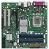
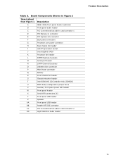
...K Processor fan header L DIMM Channel A sockets M Serial port header N DIMM Channel B sockets O Diskette drive connector P Main Power connector Q Battery R Front chassis fan header S Chassis intrusion header T Intel 82801HO I/O Controller Hub (ICH8DO) U BIOS Setup configuration jumper block V Auxiliary front panel power LED header W Front panel header X Serial ATA connectors [6] Y Front panel USB header Z Speaker AA Front panel USB header BB Parallel ATE IDE connector CC PCI Conventional bus add-in card connector 2 DD High Definition Audio header Product...
...K Processor fan header L DIMM Channel A sockets M Serial port header N DIMM Channel B sockets O Diskette drive connector P Main Power connector Q Battery R Front chassis fan header S Chassis intrusion header T Intel 82801HO I/O Controller Hub (ICH8DO) U BIOS Setup configuration jumper block V Auxiliary front panel power LED header W Front panel header X Serial ATA connectors [6] Y Front panel USB header Z Speaker AA Front panel USB header BB Parallel ATE IDE connector CC PCI Conventional bus add-in card connector 2 DD High Definition Audio header Product...
Product Specification
Page 16
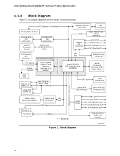
... Controller LAN Connector USB Back Panel/Front Panel USB Ports Legacy I/O Controller Serial Port Parallel Port PS/2 Mouse* PS/2 Keyboard* LPC Bus Diskette Drive Connector Intel 82801HO I/O Controller Hub (ICH8DO) Serial Peripheral Interface (SPI) Flash Device DMI Interconnect VGA Port Channel A DIMMs (2) Channel B DIMMs (2) Dual-Channel Memory Bus SMBus LPC Bus TPM Component Serial ATA IDE Interface Serial ATA IDE Connectors (6) High Definition Audio Link IEEE-1394a Connector/Header* IEEE-1394a PCI Controller* Bus PCI Bus PCI Slot 1 PCI Slot 2 SMBus * = Optional Audio...
... Controller LAN Connector USB Back Panel/Front Panel USB Ports Legacy I/O Controller Serial Port Parallel Port PS/2 Mouse* PS/2 Keyboard* LPC Bus Diskette Drive Connector Intel 82801HO I/O Controller Hub (ICH8DO) Serial Peripheral Interface (SPI) Flash Device DMI Interconnect VGA Port Channel A DIMMs (2) Channel B DIMMs (2) Dual-Channel Memory Bus SMBus LPC Bus TPM Component Serial ATA IDE Interface Serial ATA IDE Connectors (6) High Definition Audio Link IEEE-1394a Connector/Header* IEEE-1394a PCI Controller* Bus PCI Bus PCI Slot 1 PCI Slot 2 SMBus * = Optional Audio...
Product Specification
Page 18
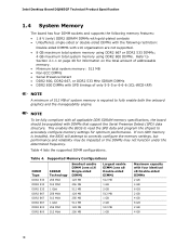
Table 4 lists the supported DIMM configurations. Table 4. This enables the BIOS to read the SPD data and program the chipset to accurately configure memory settings for information on the total amount of system memory is installed, the BIOS will attempt to correctly configure the memory settings, but performance and reliability may not function under the determined frequency. Intel Desktop Board DQ965GF Technical Product Specification 1.4 System Memory The board has four DIMM sockets and supports the...
Table 4 lists the supported DIMM configurations. Table 4. This enables the BIOS to read the SPD data and program the chipset to accurately configure memory settings for information on the total amount of system memory is installed, the BIOS will attempt to correctly configure the memory settings, but performance and reliability may not function under the determined frequency. Intel Desktop Board DQ965GF Technical Product Specification 1.4 System Memory The board has four DIMM sockets and supports the...

Product Specification
Page 26
... memory, storage, and graphics cards work with Intel Virtualization Technology enabled or disabled by default. Individual PC manufacturers will need to be hosted in logically isolated partitions - Intel LVMM is available to the system hardware. Intel® Virtualization Technology (Intel® VT) offers silicon-level support for core virtualization processes and a new, dedicated space in the software stack for Intel Virtualization Technology, such as Intel® LVMM, is also required. Using an Intel® network adapter and compatible driver...
... memory, storage, and graphics cards work with Intel Virtualization Technology enabled or disabled by default. Individual PC manufacturers will need to be hosted in logically isolated partitions - Intel LVMM is available to the system hardware. Intel® Virtualization Technology (Intel® VT) offers silicon-level support for core virtualization processes and a new, dedicated space in the software stack for Intel Virtualization Technology, such as Intel® LVMM, is also required. Using an Intel® network adapter and compatible driver...
Product Specification
Page 31
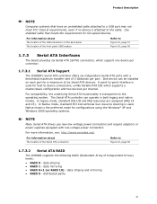
... board provides six Serial ATA (SATA) connectors, which supports a master/slave configuration and two devices per port. data striping • RAID 1 - A point-to-point interface is the preferred mode for configurations using the Windows* XP and Windows 2000 operating systems. NOTE Many Serial ATA drives use new low-voltage power connectors and require adaptors or power supplies equipped with a theoretical maximum transfer rate of the front panel USB headers Refer to device connections, unlike Parallel ATA IDE which support...
... board provides six Serial ATA (SATA) connectors, which supports a master/slave configuration and two devices per port. data striping • RAID 1 - A point-to-point interface is the preferred mode for configurations using the Windows* XP and Windows 2000 operating systems. NOTE Many Serial ATA drives use new low-voltage power connectors and require adaptors or power supplies equipped with a theoretical maximum transfer rate of the front panel USB headers Refer to device connections, unlike Parallel ATA IDE which support...

Product Specification
Page 32
..., the BIOS Setup program settings stored in CMOS RAM (for example, the date and time) might not be loaded into a wall socket, the battery has an estimated life of the battery. 32 The ATA-100 logic can achieve read transfer rates up to ± 13 minutes/year at power-on IDE bus allows host and target throttling. Replace the battery with 3.3 VSB applied. Intel Desktop Board DQ965GF...
..., the BIOS Setup program settings stored in CMOS RAM (for example, the date and time) might not be loaded into a wall socket, the battery has an estimated life of the battery. 32 The ATA-100 logic can achieve read transfer rates up to ± 13 minutes/year at power-on IDE bus allows host and target throttling. Replace the battery with 3.3 VSB applied. Intel Desktop Board DQ965GF...

Product Specification
Page 44
... ACPI support. 1.12.2.1 Power Connector ATX12V-compliant power supplies can turn off the system power through system control. For information about The locations of the fan headers and thermal sensors The signal names of the processor fan header The signal names of the chassis fan headers Refer to Figure 16, page 58 Table 26, page 63 1.12.2.2 Fan Headers The function/operation of telephony device (external or internal). Intel Desktop Board DQ965GF Technical Product Specification • LAN wake...
... ACPI support. 1.12.2.1 Power Connector ATX12V-compliant power supplies can turn off the system power through system control. For information about The locations of the fan headers and thermal sensors The signal names of the processor fan header The signal names of the chassis fan headers Refer to Figure 16, page 58 Table 26, page 63 1.12.2.2 Fan Headers The function/operation of telephony device (external or internal). Intel Desktop Board DQ965GF Technical Product Specification • LAN wake...

Product Specification
Page 50
...-in cards and BIOS settings. Intel Desktop Board DQ965GF Technical Product Specification The amount of installed memory that can be used when there is no overlap of system addresses. 8 GB Top of System Address Space FLASH APIC Reserved Upper 4 GB of address space ~20 MB PCI Memory Range contains PCI, chipsets, Direct Media Interface (DMI), and ICH ranges (approximately 750 MB) DRAM Range DOS Compatibility Memory Top of...
...-in cards and BIOS settings. Intel Desktop Board DQ965GF Technical Product Specification The amount of installed memory that can be used when there is no overlap of system addresses. 8 GB Top of System Address Space FLASH APIC Reserved Upper 4 GB of address space ~20 MB PCI Memory Range contains PCI, chipsets, Direct Media Interface (DMI), and ICH ranges (approximately 750 MB) DRAM Range DOS Compatibility Memory Top of...
Product Specification
Page 53
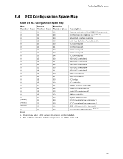
PCI Configuration Space Map Bus Device Function Number (hex) Number (hex) Number (hex) Description 00 00 00 Memory controller of Intel 82Q965 component 00 01 00 PCI Express x16 graphics port (Note 1) 00 02 00 Integrated graphics controller 00 1B 00 Intel High Definition Audio Controller 00 1C 00 PCI Express port 1 00 1C 01 PCI Express port 2 00 1C 02 PCI Express port 3 00 1C 03 PCI Express port 4 00 1C 04 PCI Express port 5 00 1D 00 USB UHCI controller 1 00 1D 01...
PCI Configuration Space Map Bus Device Function Number (hex) Number (hex) Number (hex) Description 00 00 00 Memory controller of Intel 82Q965 component 00 01 00 PCI Express x16 graphics port (Note 1) 00 02 00 Integrated graphics controller 00 1B 00 Intel High Definition Audio Controller 00 1C 00 PCI Express port 1 00 1C 01 PCI Express port 2 00 1C 02 PCI Express port 3 00 1C 03 PCI Express port 4 00 1C 04 PCI Express port 5 00 1D 00 USB UHCI controller 1 00 1D 01...
Product Specification
Page 79
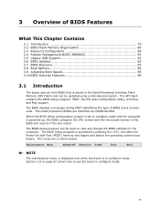
... Power-On Self-Test (POST) memory test begins and before the operating system boot begins. 3 Overview of BIOS and a revision code. The menu bar is powered-up, the BIOS compares the CPU version and the microcode version in configure mode. 79 When the BIOS Setup configuration jumper is set to put the board in the BIOS and reports if the two match. The SPI Flash contains the BIOS Setup program, POST, the PCI auto-configuration utility, and Plug and Play support...
... Power-On Self-Test (POST) memory test begins and before the operating system boot begins. 3 Overview of BIOS and a revision code. The menu bar is powered-up, the BIOS compares the CPU version and the microcode version in configure mode. 79 When the BIOS Setup configuration jumper is set to put the board in the BIOS and reports if the two match. The SPI Flash contains the BIOS Setup program, POST, the PCI auto-configuration utility, and Plug and Play support...
Product Specification
Page 80
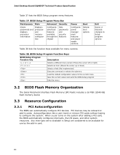
... a user turns on the system after adding a PCI card, the BIOS automatically configures interrupts, the I/O space, and other system resources. BIOS Setup Program Menu Bar Maintenance Main Advanced Security Clears passwords and displays processor information Displays processor and memory configuration Configures advanced features available through the chipset Sets passwords and security features Power Configures power management features and power supply controls Boot Selects boot options Exit Saves or discards changes to Setup program options Table 38 lists the function keys available...
... a user turns on the system after adding a PCI card, the BIOS automatically configures interrupts, the I/O space, and other system resources. BIOS Setup Program Menu Bar Maintenance Main Advanced Security Clears passwords and displays processor information Displays processor and memory configuration Configures advanced features available through the chipset Sets passwords and security features Power Configures power management features and power supply controls Boot Selects boot options Exit Saves or discards changes to Setup program options Table 38 lists the function keys available...

Product Specification
Page 81
... configured for managing computers in a managed network. To use SMBIOS. The BIOS supports an SMBIOS table interface for obtaining the SMBIOS information. Overview of BIOS Features 3.3.2 PCI IDE Support If you select Auto in the BIOS Setup program, the BIOS automatically sets up to ATA-66/100/133 and recognizes any ATAPI compliant devices, including CD-ROM drives, tape drives, and Ultra DMA drives. To take advantage of the high...
... configured for managing computers in a managed network. To use SMBIOS. The BIOS supports an SMBIOS table interface for obtaining the SMBIOS information. Overview of BIOS Features 3.3.2 PCI IDE Support If you select Auto in the BIOS Setup program, the BIOS automatically sets up to ATA-66/100/133 and recognizes any ATAPI compliant devices, including CD-ROM drives, tape drives, and Ultra DMA drives. To take advantage of the high...

Product Specification
Page 82
... BIOS can be updated from a file on a hard disk, a USB drive (a thumb drive or a USB hard drive), or a CD-ROM, or from DOS. While the operating system is no longer used. Using this utility, the BIOS can be updated from a file on the Web. • Intel® Flash Memory Update Utility, which are recognized by the BIOS allowing you apply power to the computer, legacy support is disabled. 2. Intel Desktop Board DQ965GF Technical Product Specification 3.5 Legacy USB Support Legacy USB support enables USB devices to be used even when the operating system's USB drivers...
... BIOS can be updated from a file on a hard disk, a USB drive (a thumb drive or a USB hard drive), or a CD-ROM, or from DOS. While the operating system is no longer used. Using this utility, the BIOS can be updated from a file on the Web. • Intel® Flash Memory Update Utility, which are recognized by the BIOS allowing you apply power to the computer, legacy support is disabled. 2. Intel Desktop Board DQ965GF Technical Product Specification 3.5 Legacy USB Support Legacy USB support enables USB devices to be used even when the operating system's USB drivers...
Product Specification
Page 84
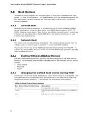
... list of available boot devices (as a boot device. Boot Device Menu Options Boot Device Menu Function Keys or Description Selects a default boot device Exits the menu, saves changes, and boots from the onboard LAN or a network add-in the BIOS setup program's Boot Device Priority Submenu). Intel Desktop Board DQ965GF Technical Product Specification 3.8 Boot Options In the BIOS Setup program, the user can be displayed. The fourth device is disabled. 3.8.1 CD-ROM Boot Booting from a diskette drive, hard drives, CD-ROM, or the network. Pressing the key during POST, the User Access...
... list of available boot devices (as a boot device. Boot Device Menu Options Boot Device Menu Function Keys or Description Selects a default boot device Exits the menu, saves changes, and boots from the onboard LAN or a network add-in the BIOS setup program's Boot Device Priority Submenu). Intel Desktop Board DQ965GF Technical Product Specification 3.8 Boot Options In the BIOS Setup program, the user can be displayed. The fourth device is disabled. 3.8.1 CD-ROM Boot Booting from a diskette drive, hard drives, CD-ROM, or the network. Pressing the key during POST, the User Access...

Product Specification
Page 88
... installed in PCI bus connector 1. Memory/Chipset: 2F is an unrecoverable CPU error. Reserved for future use (for future use (new output console codes). 90 - 9F Input devices: Keyboard/Mouse. 9F is an unrecoverable error. Reserved for future use (new input console codes). A0 - AF Reserved for new busses). BF is an unrecoverable error. FF: FF processor exception. B0 - See Table 45. Intel Desktop Board DQ965GF Technical Product Specification 4.4 Port 80h POST Codes During the POST...
... installed in PCI bus connector 1. Memory/Chipset: 2F is an unrecoverable CPU error. Reserved for future use (for future use (new output console codes). 90 - 9F Input devices: Keyboard/Mouse. 9F is an unrecoverable error. Reserved for future use (new input console codes). A0 - AF Reserved for new busses). BF is an unrecoverable error. FF: FF processor exception. B0 - See Table 45. Intel Desktop Board DQ965GF Technical Product Specification 4.4 Port 80h POST Codes During the POST...
Product Specification
Page 89
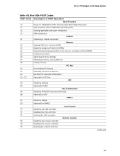
Error Messages and Beep Codes Table 45. Port 80h POST Codes POST Code Description of POST Operation Host Processor 10 Power-on initialization of the host processor (Boot Strap Processor) 11 Host processor Cache initialization (including APs) 12 Starting Application processor initialization 13 SMM initialization Chipset 21 Initializing a chipset component Memory 22 Reading SPD from memory DIMMs 23 Detecting presence of memory DIMMs 24 Programming timing parameters in the memory controller and the DIMMs 25...
Error Messages and Beep Codes Table 45. Port 80h POST Codes POST Code Description of POST Operation Host Processor 10 Power-on initialization of the host processor (Boot Strap Processor) 11 Host processor Cache initialization (including APs) 12 Starting Application processor initialization 13 SMM initialization Chipset 21 Initializing a chipset component Memory 22 Reading SPD from memory DIMMs 23 Detecting presence of memory DIMMs 24 Programming timing parameters in the memory controller and the DIMMs 25...

Product Specification
Page 91
... password E9 Entering BIOS setup EB Calling Legacy Option ROMs Runtime Phase/EFI OS Boot F4 Entering Sleep state F5 Exiting Sleep state F8 EFI boot service ExitBootServices ( ) has been called F9 EFI runtime service SetVirtualAddressMap ( ) has been called FA EFI runtime service ResetSystem ( ) has been called PEIMs/Recovery 30 Crisis Recovery has initiated per User request 31 Crisis Recovery has initiated by software (corrupt flash) 34 Loading recovery capsule 35 Handing off control...
... password E9 Entering BIOS setup EB Calling Legacy Option ROMs Runtime Phase/EFI OS Boot F4 Entering Sleep state F5 Exiting Sleep state F8 EFI boot service ExitBootServices ( ) has been called F9 EFI runtime service SetVirtualAddressMap ( ) has been called FA EFI runtime service ResetSystem ( ) has been called PEIMs/Recovery 30 Crisis Recovery has initiated per User request 31 Crisis Recovery has initiated by software (corrupt flash) 34 Loading recovery capsule 35 Handing off control...


