Product Specification
Page 2
... 2006 September 2006 ii Changes in the following areas: • Updated supported processors in Table 1 and Section 1.3. • Updated supported total memory in Table 1 and Section 1.4. • Listed specific SPD timings for DDR2 800 DIMMs in Section 1.4. • Updated supported memory configurations in Table 32. • Added Chapter 5. Moved regulatory compliance information from Chapter 1 to Chapter 5. Second release of the Intel® Desktop Board DP965LT Technical Product...
... 2006 September 2006 ii Changes in the following areas: • Updated supported processors in Table 1 and Section 1.3. • Updated supported total memory in Table 1 and Section 1.4. • Listed specific SPD timings for DDR2 800 DIMMs in Section 1.4. • Updated supported memory configurations in Table 32. • Added Chapter 5. Moved regulatory compliance information from Chapter 1 to Chapter 5. Second release of the Intel® Desktop Board DP965LT Technical Product...

Product Specification
Page 8
...70 3.3.2 PCI IDE Support 71 3.4 System Management BIOS (SMBIOS 71 3.5 Legacy USB Support 72 3.6 BIOS Updates 72 3.6.1 Language Support 73 3.6.2 Custom Splash Screen 73 3.7 BIOS Recovery 73 3.8 Boot Options 74 3.8.1 CD-ROM Boot 74 3.8.2 Network Boot 74 3.8.3 Booting Without Attached Devices 74 3.8.4 Changing the Default Boot Device During POST 74 3.9 Adjusting Boot Speed 75 3.9.1 Peripheral Selection and Configuration 75 3.9.2 BIOS Boot Optimizations 75 3.10 BIOS Security Features 76 4 Error Messages and Beep Codes 4.1 Speaker 77 4.2 BIOS Beep Codes 77 4.3 BIOS Error Messages...
...70 3.3.2 PCI IDE Support 71 3.4 System Management BIOS (SMBIOS 71 3.5 Legacy USB Support 72 3.6 BIOS Updates 72 3.6.1 Language Support 73 3.6.2 Custom Splash Screen 73 3.7 BIOS Recovery 73 3.8 Boot Options 74 3.8.1 CD-ROM Boot 74 3.8.2 Network Boot 74 3.8.3 Booting Without Attached Devices 74 3.8.4 Changing the Default Boot Device During POST 74 3.9 Adjusting Boot Speed 75 3.9.1 Peripheral Selection and Configuration 75 3.9.2 BIOS Boot Optimizations 75 3.10 BIOS Security Features 76 4 Error Messages and Beep Codes 4.1 Speaker 77 4.2 BIOS Beep Codes 77 4.3 BIOS Error Messages...

Product Specification
Page 9
... 1. Board Components Shown in Figure 1 15 3. System Memory Map 45 11. Single Channel (Asymmetric) Mode Configuration with Two DIMMs 22 5. LAN Connector LED Locations 33 12. Location of Pressing the Power Switch 36 8. Connection Diagram for Front Panel USB Headers 59 19. Wake-up Devices and Events 38 10. Dual Channel (Interleaved) Mode Configuration with One DIMM .......... 24 8. Thermal Sensors and Fan Headers 35 13. Back Panel Connectors 51 16. Memory Operating Frequencies 19 5. Memory Channel and DIMM Configuration 21 4. Dual Channel (Interleaved) Mode...
... 1. Board Components Shown in Figure 1 15 3. System Memory Map 45 11. Single Channel (Asymmetric) Mode Configuration with Two DIMMs 22 5. LAN Connector LED Locations 33 12. Location of Pressing the Power Switch 36 8. Connection Diagram for Front Panel USB Headers 59 19. Wake-up Devices and Events 38 10. Dual Channel (Interleaved) Mode Configuration with One DIMM .......... 24 8. Thermal Sensors and Fan Headers 35 13. Back Panel Connectors 51 16. Memory Operating Frequencies 19 5. Memory Channel and DIMM Configuration 21 4. Dual Channel (Interleaved) Mode...

Product Specification
Page 10
... Panel Header 57 27. BIOS Setup Configuration Jumper Settings 60 30. Supervisor and User Password Functions 76 39. Main Power Connector 56 26. Fan Header Current Capability 63 32. BIOS Setup Program Menu Bar 70 35. Boot Device Menu Options 74 38. Beep Codes 77 40. BIOS Error Messages 77 41. Interrupts 48 15. HD Audio Link Header 54 18. PCI Interrupt Routing Map 49 16. Processor and Auxiliary Rear Chassis Fan Headers 55 24. Front Panel Audio Header 54 19. DC Loading Characteristics 63 31. Serial Port Header...
... Panel Header 57 27. BIOS Setup Configuration Jumper Settings 60 30. Supervisor and User Password Functions 76 39. Main Power Connector 56 26. Fan Header Current Capability 63 32. BIOS Setup Program Menu Bar 70 35. Boot Device Menu Options 74 38. Beep Codes 77 40. BIOS Error Messages 77 41. Interrupts 48 15. HD Audio Link Header 54 18. PCI Interrupt Routing Map 49 16. Processor and Auxiliary Rear Chassis Fan Headers 55 24. Front Panel Audio Header 54 19. DC Loading Characteristics 63 31. Serial Port Header...

Product Specification
Page 12
... Desktop Board DP965LT. Table 1. Intel Desktop Board DP965LT Technical Product Specification 1.1 Overview 1.1.1 Feature Summary Table 1 summarizes the major features of : • Intel® 82P965 Memory Controller Hub (MCH) • Intel® 82801HB I/O Controller Hub (ICH8) 6-channel (5.1) audio subsystem using the SigmaTel* STAC9227 audio codec Legacy I/O controller for diskette drive, serial, parallel, and PS/2* ports Support for USB 2.0 devices • 10 USB ports • Two IEEE-1394a interfaces: one back panel connector and one front-panel header • Four Serial ATA IDE...
... Desktop Board DP965LT. Table 1. Intel Desktop Board DP965LT Technical Product Specification 1.1 Overview 1.1.1 Feature Summary Table 1 summarizes the major features of : • Intel® 82P965 Memory Controller Hub (MCH) • Intel® 82801HB I/O Controller Hub (ICH8) 6-channel (5.1) audio subsystem using the SigmaTel* STAC9227 audio codec Legacy I/O controller for diskette drive, serial, parallel, and PS/2* ports Support for USB 2.0 devices • 10 USB ports • Two IEEE-1394a interfaces: one back panel connector and one front-panel header • Four Serial ATA IDE...

Product Specification
Page 15
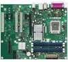
... M LGA775 processor socket N Intel 82P965 MCH O Processor fan header P DIMM Channel A sockets Q Serial port header R DIMM Channel B sockets S Diskette drive connector T Main Power connector U Battery V Front chassis fan header W Chassis intrusion header X Intel 82801HB I/O Controller Hub (ICH8) Y BIOS Setup configuration jumper block Z Auxiliary front panel power LED header AA Front panel header BB Serial ATA connectors [4] CC Speaker DD Parallel ATE IDE connector EE Front panel USB headers [2] FF IEEE-1394a header GG PCI Conventional bus add-in card...
... M LGA775 processor socket N Intel 82P965 MCH O Processor fan header P DIMM Channel A sockets Q Serial port header R DIMM Channel B sockets S Diskette drive connector T Main Power connector U Battery V Front chassis fan header W Chassis intrusion header X Intel 82801HB I/O Controller Hub (ICH8) Y BIOS Setup configuration jumper block Z Auxiliary front panel power LED header AA Front panel header BB Serial ATA connectors [4] CC Speaker DD Parallel ATE IDE connector EE Front panel USB headers [2] FF IEEE-1394a header GG PCI Conventional bus add-in card...

Product Specification
Page 18
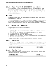
... Serial Presence Detect (SPD) data structure. Intel Desktop Board DP965LT Technical Product Specification 1.4 System Memory The board has four DIMM sockets and support the following memory features: • 1.8 V (only) DDR2 SDRAM DIMMs with gold-plated contacts • Unbuffered, single-sided or double-sided DIMMs with the following restriction: Double-sided DIMMS with x16 organization are not supported. • 8 GB maximum total system memory using DDR2...
... Serial Presence Detect (SPD) data structure. Intel Desktop Board DP965LT Technical Product Specification 1.4 System Memory The board has four DIMM sockets and support the following memory features: • 1.8 V (only) DDR2 SDRAM DIMMs with gold-plated contacts • Unbuffered, single-sided or double-sided DIMMs with the following restriction: Double-sided DIMMS with x16 organization are not supported. • 8 GB maximum total system memory using DDR2...
Product Specification
Page 28
... The location of the board. Use the BIOS Setup program to ± 13 minutes/year at speeds up event interface • PCI power management support The BIOS Setup program provides configuration options for one . When the computer is not plugged into CMOS RAM at power-on the component side of the parallel port connector Refer to 115.2 kbits/sec with serialized IRQ support for PCI systems • PS/2-style mouse and keyboard interfaces...
... The location of the board. Use the BIOS Setup program to ± 13 minutes/year at speeds up event interface • PCI power management support The BIOS Setup program provides configuration options for one . When the computer is not plugged into CMOS RAM at power-on the component side of the parallel port connector Refer to 115.2 kbits/sec with serialized IRQ support for PCI systems • PS/2-style mouse and keyboard interfaces...
Product Specification
Page 44
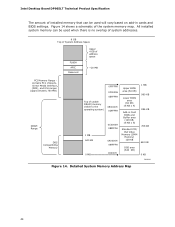
Intel Desktop Board DP965LT Technical Product Specification The amount of installed memory that can be used when there is no overlap of system addresses. 8 GB Top of System Address Space FLASH APIC Reserved Upper 4 GB of address space ~20 MB PCI Memory Range contains PCI, chipsets, Direct Media Interface (DMI), and ICH ranges (approximately 750 MB) DRAM Range DOS Compatibility Memory Top of the system memory map...
Intel Desktop Board DP965LT Technical Product Specification The amount of installed memory that can be used when there is no overlap of system addresses. 8 GB Top of System Address Space FLASH APIC Reserved Upper 4 GB of address space ~20 MB PCI Memory Range contains PCI, chipsets, Direct Media Interface (DMI), and ICH ranges (approximately 750 MB) DRAM Range DOS Compatibility Memory Top of the system memory map...

Product Specification
Page 47
... IDE controller 00 1F 02 Serial ATA controller #1 00 1F 05 Serial ATA controller #2 00 1F 03 SMBus controller 00 19 00 Gigabit LAN controller (Note 2) 00 00 PCI Conventional bus connector 1 (Note 2) 01 00 PCI Conventional bus connector 2 (Note 2) 02 00 PCI Conventional bus connector 3 (Note 2) 03 00 IEEE-1394a controller 01 00 00 PCI Express Video Controller (Note 1) Notes: 1. Bus number is installed. 2. Technical Reference 2.4 PCI Configuration Space Map Table 13. Present only when a PCI Express x16 graphics card...
... IDE controller 00 1F 02 Serial ATA controller #1 00 1F 05 Serial ATA controller #2 00 1F 03 SMBus controller 00 19 00 Gigabit LAN controller (Note 2) 00 00 PCI Conventional bus connector 1 (Note 2) 01 00 PCI Conventional bus connector 2 (Note 2) 02 00 PCI Conventional bus connector 3 (Note 2) 03 00 IEEE-1394a controller 01 00 00 PCI Express Video Controller (Note 1) Notes: 1. Bus number is installed. 2. Technical Reference 2.4 PCI Configuration Space Map Table 13. Present only when a PCI Express x16 graphics card...

Product Specification
Page 59
.... • Use only a front panel USB connector that conforms to the USB 2.0 specification for IEEE 1394a Header 59 D+ Ground Key (no pin) +12 V DC 8 7 +12 V DC TPB- 6 5 TPB+ Ground 4 3 Ground TPA- 2 1 TPA+ OM18332 Figure 19. Ground 10 Key (no pin) 12 3 4 Power (+5 V DC) D- 5 6 D+ 7 8 Ground 10 No connect One USB Port OM18317 Figure 18. Connection Diagram for high-speed USB devices. One USB Port Power (+5 V DC) D- Connection Diagram for Front Panel USB Headers 2.7.2.5 Front Panel IEEE 1394a Header Figure 19 is a connection diagram for...
.... • Use only a front panel USB connector that conforms to the USB 2.0 specification for IEEE 1394a Header 59 D+ Ground Key (no pin) +12 V DC 8 7 +12 V DC TPB- 6 5 TPB+ Ground 4 3 Ground TPA- 2 1 TPA+ OM18332 Figure 19. Ground 10 Key (no pin) 12 3 4 Power (+5 V DC) D- 5 6 D+ 7 8 Ground 10 No connect One USB Port OM18317 Figure 18. Connection Diagram for high-speed USB devices. One USB Port Power (+5 V DC) D- Connection Diagram for Front Panel USB Headers 2.7.2.5 Front Panel IEEE 1394a Header Figure 19 is a connection diagram for...

Product Specification
Page 69
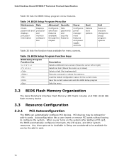
... 3.2 BIOS Flash Memory Organization 70 3.3 Resource Configuration 70 3.4 System Management BIOS (SMBIOS 71 3.5 Legacy USB Support 72 3.6 BIOS Updates 72 3.7 BIOS Recovery 73 3.8 Boot Options 74 3.9 Adjusting Boot Speed 75 3.10 BIOS Security Features 76 3.1 Introduction The board uses an Intel BIOS that is stored in the BIOS and reports if the two match. When the BIOS Setup configuration jumper is set to configure mode and the computer is in configure mode. 69 The BIOS Setup program is shown below. Maintenance Main Advanced Security Power Boot...
... 3.2 BIOS Flash Memory Organization 70 3.3 Resource Configuration 70 3.4 System Management BIOS (SMBIOS 71 3.5 Legacy USB Support 72 3.6 BIOS Updates 72 3.7 BIOS Recovery 73 3.8 Boot Options 74 3.9 Adjusting Boot Speed 75 3.10 BIOS Security Features 76 3.1 Introduction The board uses an Intel BIOS that is stored in the BIOS and reports if the two match. When the BIOS Setup configuration jumper is set to configure mode and the computer is in configure mode. 69 The BIOS Setup program is shown below. Maintenance Main Advanced Security Power Boot...
Product Specification
Page 70
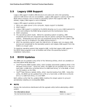
... Setup are considered to Setup program options Table 35 lists the function keys available for menu screens. Table 34. BIOS Setup Program Menu Bar Maintenance Main Advanced Security Clears passwords and displays processor information Displays processor and memory configuretion Configures advanced features available through the chipset Sets passwords and security features Power Configures power management features and power supply controls Boot Selects boot options Exit Saves or discards changes to be onboard or add-in card. 70 BIOS Setup Program Function Keys BIOS Setup...
... Setup are considered to Setup program options Table 35 lists the function keys available for menu screens. Table 34. BIOS Setup Program Menu Bar Maintenance Main Advanced Security Clears passwords and displays processor information Displays processor and memory configuretion Configures advanced features available through the chipset Sets passwords and security features Power Configures power management features and power supply controls Boot Selects boot options Exit Saves or discards changes to be onboard or add-in card. 70 BIOS Setup Program Function Keys BIOS Setup...

Product Specification
Page 71
... IDE interface supports hard drives up the PCI IDE connector with independent I/O channel support. Overview of BIOS Features 3.3.2 PCI IDE Support If you select Auto in the BIOS Setup program. To take advantage of the high capacities typically available today, hard drives are required: • An ATA-66/100/133 peripheral device • An ATA-66/100/133 compatible cable • ATA-66/100/133 operating system device drivers NOTE Do not connect an ATA device...
... IDE interface supports hard drives up the PCI IDE connector with independent I/O channel support. Overview of BIOS Features 3.3.2 PCI IDE Support If you select Auto in the BIOS Setup program. To take advantage of the high capacities typically available today, hard drives are required: • An ATA-66/100/133 peripheral device • An ATA-66/100/133 compatible cable • ATA-66/100/133 operating system device drivers NOTE Do not connect an ATA device...
Product Specification
Page 72
... Legacy USB support was set to Disabled in the BIOS Setup program is set to Enabled. When you to use a USB keyboard to enter and configure the BIOS Setup program and the maintenance menu. 4. NOTE Review the instructions distributed with the upgrade utility before attempting a BIOS update. While the operating system is disabled. 2. For information about The Intel World Wide Web site Refer to prevent accidentally installing an incompatible BIOS. POST completes. 5. Intel Desktop Board DP965LT Technical Product Specification 3.5 Legacy USB Support Legacy USB support enables USB...
... Legacy USB support was set to Disabled in the BIOS Setup program is set to Enabled. When you to use a USB keyboard to enter and configure the BIOS Setup program and the maintenance menu. 4. NOTE Review the instructions distributed with the upgrade utility before attempting a BIOS update. While the operating system is disabled. 2. For information about The Intel World Wide Web site Refer to prevent accidentally installing an incompatible BIOS. POST completes. 5. Intel Desktop Board DP965LT Technical Product Specification 3.5 Legacy USB Support Legacy USB support enables USB...
Product Specification
Page 74
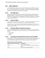
... key during POST, the User Access Level in the BIOS Setup program's Security menu must be set in card with a remote boot ROM installed. To use this key during POST automatically forces booting from the onboard LAN or a network add-in the BIOS setup program's Boot Device Priority Submenu). Boot Device Menu Options Boot Device Menu Function Keys or Description Selects a default boot device Exits the menu, saves changes, and boots from the next defined drive. 3.8.2 Network Boot The network can choose to be displayed. Intel Desktop Board DP965LT Technical Product Specification...
... key during POST, the User Access Level in the BIOS Setup program's Security menu must be set in card with a remote boot ROM installed. To use this key during POST automatically forces booting from the onboard LAN or a network add-in the BIOS setup program's Boot Device Priority Submenu). Boot Device Menu Options Boot Device Menu Function Keys or Description Selects a default boot device Exits the menu, saves changes, and boots from the next defined drive. 3.8.2 Network Boot The network can choose to be displayed. Intel Desktop Board DP965LT Technical Product Specification...
Product Specification
Page 76
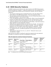
... change all options Can change a Supervisor Password limited number Enter Password of setting the supervisor password and user password. Intel Desktop Board DP965LT Technical Product Specification 3.10 BIOS Security Features The BIOS includes security features that restrict access to Enter Setup None Password During Boot None Supervisor None User User Supervisor or Supervisor or user user 76 Password to the BIOS Setup program and who can be up to access Setup. This is the supervisor mode. • The user password gives restricted access to boot...
... change all options Can change a Supervisor Password limited number Enter Password of setting the supervisor password and user password. Intel Desktop Board DP965LT Technical Product Specification 3.10 BIOS Security Features The BIOS includes security features that restrict access to Enter Setup None Password During Boot None Supervisor None User User Supervisor or Supervisor or user user 76 Password to the BIOS Setup program and who can be up to access Setup. This is the supervisor mode. • The user password gives restricted access to boot...

Product Specification
Page 78
... recovery failure. Reserved for debug. 10 - 1F 20 - 2F 30 - 3F 40 - 4F 50 - 5F 60 - 6F 70 - 7F 80 - 8F Host Processors: 1F is an unrecoverable CPU error. Reserved for future use (new output console codes). 90 - 9F Input devices: Keyboard/Mouse. 9F is an unrecoverable error. Intel Desktop Board DP965LT Technical Product Specification 4.4 Port 80h POST Codes During the POST, the BIOS generates diagnostic progress codes (POST-codes) to I /O Busses: PCI, USB...
... recovery failure. Reserved for debug. 10 - 1F 20 - 2F 30 - 3F 40 - 4F 50 - 5F 60 - 6F 70 - 7F 80 - 8F Host Processors: 1F is an unrecoverable CPU error. Reserved for future use (new output console codes). 90 - 9F Input devices: Keyboard/Mouse. 9F is an unrecoverable error. Intel Desktop Board DP965LT Technical Product Specification 4.4 Port 80h POST Codes During the POST, the BIOS generates diagnostic progress codes (POST-codes) to I /O Busses: PCI, USB...

Product Specification
Page 79
... Configuring memory 26 Optimizing memory settings 27 Initializing memory, such as ECC init 28 Testing memory PCI Bus 50 Enumerating PCI busses 51 Allocating resources to PCI bus 52 53 - 57 Hot Plug PCI controller initialization Reserved for PCI Bus USB 58 Resetting USB bus 59 Reserved for USB ATA/ATAPI/SATA 5A Resetting PATA/SATA bus and all devices 5B Reserved for ATA 5C Resetting SMBUS SMBus 5D Reserved for SMBUS Local Console 70 Resetting the VGA controller 71 Disabling...
... Configuring memory 26 Optimizing memory settings 27 Initializing memory, such as ECC init 28 Testing memory PCI Bus 50 Enumerating PCI busses 51 Allocating resources to PCI bus 52 53 - 57 Hot Plug PCI controller initialization Reserved for PCI Bus USB 58 Resetting USB bus 59 Reserved for USB ATA/ATAPI/SATA 5A Resetting PATA/SATA bus and all devices 5B Reserved for ATA 5C Resetting SMBUS SMBus 5D Reserved for SMBUS Local Console 70 Resetting the VGA controller 71 Disabling...
Product Specification
Page 81
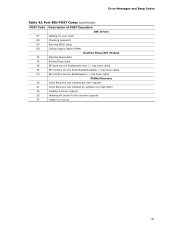
Error Messages and Beep Codes Table 42. Port 80h POST Codes (continued) POST Code Description of POST Operation DXE Drivers E7 Waiting for user input E8 Checking password E9 Entering BIOS setup EB Calling Legacy Option ROMs Runtime Phase/EFI OS Boot F4 Entering Sleep state F5 Exiting Sleep state F8 EFI boot service ExitBootServices ( ) has been called F9 EFI runtime service SetVirtualAddressMap ( ) has been called FA EFI runtime service ResetSystem ( ) has been called PEIMs/Recovery 30 Crisis...
Error Messages and Beep Codes Table 42. Port 80h POST Codes (continued) POST Code Description of POST Operation DXE Drivers E7 Waiting for user input E8 Checking password E9 Entering BIOS setup EB Calling Legacy Option ROMs Runtime Phase/EFI OS Boot F4 Entering Sleep state F5 Exiting Sleep state F8 EFI boot service ExitBootServices ( ) has been called F9 EFI runtime service SetVirtualAddressMap ( ) has been called FA EFI runtime service ResetSystem ( ) has been called PEIMs/Recovery 30 Crisis...


