
Product Specification
Page 5
Contents 1 Product Description 1.1 Overview 9 1.1.1 Feature Summary 9 1.1.2 Board Layout 11 1.1.3 Block Diagram 13 1.2 Legacy Considerations 14 1.3 Online Support 14 1.4 Processor 14 1.5 System Memory 15 1.5.1 Memory Configurations 16 1.6 Intel® P55 Express Chipset 18 1.6.1 USB 18 1.6.2 SATA Interfaces 18 1.7 Real-Time Clock Subsystem 19 1.8 Legacy I/O Controller 20 1.8.1 Consumer Infrared (CIR 20 1.9 Audio Subsystem 21 1.9.1 Audio Subsystem ...
Contents 1 Product Description 1.1 Overview 9 1.1.1 Feature Summary 9 1.1.2 Board Layout 11 1.1.3 Block Diagram 13 1.2 Legacy Considerations 14 1.3 Online Support 14 1.4 Processor 14 1.5 System Memory 15 1.5.1 Memory Configurations 16 1.6 Intel® P55 Express Chipset 18 1.6.1 USB 18 1.6.2 SATA Interfaces 18 1.7 Real-Time Clock Subsystem 19 1.8 Legacy I/O Controller 20 1.8.1 Consumer Infrared (CIR 20 1.9 Audio Subsystem 21 1.9.1 Audio Subsystem ...

Product Specification
Page 7
...15 4. Effects of the Onboard Power Button 35 9. IEEE 1394a Header 43 11. S/PDIF Header 43 14. Processor, Front and Rear Chassis (4-Pin) Fan Headers 44 16. Thermal Sensors and Fan Headers 26 7. Connection Diagram for Front Panel USB Headers 50 14. Localized High Temperature Zones... LED States 24 5. Component-side Connectors and Headers 41 12. Power States and Targeted System Power 28 7. Locations of the Jumper Block 51 16. Back Panel Connectors 40 11. Feature Summary 9 2. System Memory Map 39 9. Front Panel Audio Header 43 12. Connection Diagram for IEEE...
...15 4. Effects of the Onboard Power Button 35 9. IEEE 1394a Header 43 11. S/PDIF Header 43 14. Processor, Front and Rear Chassis (4-Pin) Fan Headers 44 16. Thermal Sensors and Fan Headers 26 7. Connection Diagram for Front Panel USB Headers 50 14. Localized High Temperature Zones... LED States 24 5. Component-side Connectors and Headers 41 12. Power States and Targeted System Power 28 7. Locations of the Jumper Block 51 16. Back Panel Connectors 40 11. Feature Summary 9 2. System Memory Map 39 9. Front Panel Audio Header 43 12. Connection Diagram for IEEE...
Product Specification
Page 9
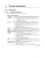
... ports • Six internal Serial ATA (SATA) 3.0 Gb/s interfaces through the Intel P55 PCH with four DIMMs using 2 Gb memory technology • Support for non-ECC memory • Support for PCI Express* Revision 2.0 • Suspend to 16 GB of system memory with RAID support (black) • ...DDR3 1600 MHz, DDR3 1333 MHz, and DDR3 1066 MHz DIMMs • Support for 1 Gb and 2 Gb memory technology • Support for up to RAM support • Wake on PCI, PCI Express, LAN, front panel, CIR, and USB ports continued 9 Feature Summary Form Factor Processor Memory Chipset Audio ATX...
... ports • Six internal Serial ATA (SATA) 3.0 Gb/s interfaces through the Intel P55 PCH with four DIMMs using 2 Gb memory technology • Support for non-ECC memory • Support for PCI Express* Revision 2.0 • Suspend to 16 GB of system memory with RAID support (black) • ...DDR3 1600 MHz, DDR3 1333 MHz, and DDR3 1066 MHz DIMMs • Support for 1 Gb and 2 Gb memory technology • Support for up to RAM support • Wake on PCI, PCI Express, LAN, front panel, CIR, and USB ports continued 9 Feature Summary Form Factor Processor Memory Chipset Audio ATX...

Product Specification
Page 10
Feature Summary (continued) LAN Support Gigabit (10/100/1000 Mbits/s) LAN subsystem using the Intel® 82578DC Gigabit Ethernet Controller Expansion Capabilities • One PCI Express 2.0 x16 (x8 when the PCI Express x8 connector is used) bus add-in card ... headers using PWM control • Two fan sense inputs used to monitor fan activity • Fan speed control using voltage control for 4-pin fan headers (processor and front and rear chassis) with selectable support in BIOS for 3 wire fans • Support for Platform Environmental Control Interface (PECI) 10...
Feature Summary (continued) LAN Support Gigabit (10/100/1000 Mbits/s) LAN subsystem using the Intel® 82578DC Gigabit Ethernet Controller Expansion Capabilities • One PCI Express 2.0 x16 (x8 when the PCI Express x8 connector is used) bus add-in card ... headers using PWM control • Two fan sense inputs used to monitor fan activity • Fan speed control using voltage control for 4-pin fan headers (processor and front and rear chassis) with selectable support in BIOS for 3 wire fans • Support for Platform Environmental Control Interface (PECI) 10...

Product Specification
Page 12
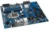
...I PCI Express 2.0 x1 connector J PCI Express 2.0 x16 connector K Battery L Back panel connectors M 12 V processor core voltage connector (2 x 4) N Processor fan header O Processor LED (red) P Voltage regulator LED (red) Q Processor socket R POST code LED display S DIMM Channel A socket T DIMM Channel B socket U Onboard power button ...panel power LED header CC Front chassis fan header DD USB 2.0 headers (2) EE IEEE 1394a header FF Intel P55 Express Chipset GG BIOS configuration jumper block HH Serial ATA connectors II Chassis intrusion header JJ USB 2.0 ...
...I PCI Express 2.0 x1 connector J PCI Express 2.0 x16 connector K Battery L Back panel connectors M 12 V processor core voltage connector (2 x 4) N Processor fan header O Processor LED (red) P Voltage regulator LED (red) Q Processor socket R POST code LED display S DIMM Channel A socket T DIMM Channel B socket U Onboard power button ...panel power LED header CC Front chassis fan header DD USB 2.0 headers (2) EE IEEE 1394a header FF Intel P55 Express Chipset GG BIOS configuration jumper block HH Serial ATA connectors II Chassis intrusion header JJ USB 2.0 ...
Product Specification
Page 14
...: http://www.intel.com/products/motherboard/DP55WG/index.htm http://support.intel.com/support/motherboards/desktop http://www.intel.com/products/motherboard/DP55WG/index.htm http://processormatch.intel.com http://www.intel.com/products/desktop/chipsets/index.htm http://downloadcenter.intel.com http://support.intel.com/support/motherboards/desktop/sb/CS025414.htm http://www.intel.com/support/go/buildit 1.4 Processor The board is...
...: http://www.intel.com/products/motherboard/DP55WG/index.htm http://support.intel.com/support/motherboards/desktop http://www.intel.com/products/motherboard/DP55WG/index.htm http://processormatch.intel.com http://www.intel.com/products/desktop/chipsets/index.htm http://downloadcenter.intel.com http://support.intel.com/support/motherboards/desktop/sb/CS025414.htm http://www.intel.com/support/go/buildit 1.4 Processor The board is...
Product Specification
Page 16
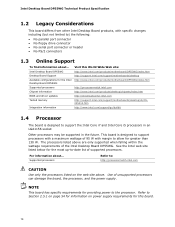
.../motherboards/desktop/sb/cs011965.htm 16 This mode is used when only a single DIMM is enabled when the installed memory capacities of memory organization: • Dual channel (Interleaved) mode. If different speed DIMMs are unequal. For information about... Intel Desktop Board DP55WG Technical Product Specification 1.5.1 Memory Configurations The Intel Core i7 and Intel Core i5 processors...
.../motherboards/desktop/sb/cs011965.htm 16 This mode is used when only a single DIMM is enabled when the installed memory capacities of memory organization: • Dual channel (Interleaved) mode. If different speed DIMMs are unequal. For information about... Intel Desktop Board DP55WG Technical Product Specification 1.5.1 Memory Configurations The Intel Core i7 and Intel Core i5 processors...

Product Specification
Page 18
...XP, Windows Vista*, and Windows 7* operating systems. NOTE Many SATA drives use of 3 Gb/s per port. For information about The Intel P55 Express Chipset Resources used by the chipset Refer to http://www.intel.com/products/desktop/chipsets/index.htm Chapter 2 1.6.1 USB The board supports up to device... for a maximum of the SATA connectors Refer to the processor and the USB, SATA, LPC, LAN, PCI, and PCIe interfaces. The SATA controller can be installed on the back panel The location of the Intel P55 Express Platform Controller Hub (PCH) provides interfaces to Figure 11...
...XP, Windows Vista*, and Windows 7* operating systems. NOTE Many SATA drives use of 3 Gb/s per port. For information about The Intel P55 Express Chipset Resources used by the chipset Refer to http://www.intel.com/products/desktop/chipsets/index.htm Chapter 2 1.6.1 USB The board supports up to device... for a maximum of the SATA connectors Refer to the processor and the USB, SATA, LPC, LAN, PCI, and PCIe interfaces. The SATA controller can be installed on the back panel The location of the Intel P55 Express Platform Controller Hub (PCH) provides interfaces to Figure 11...

Product Specification
Page 25
... all three fans, that can adjust the fan speed or switch the fans on the chassis that detects if the chassis cover is in the processor and PCH • Power supply monitoring of five voltages (+5 V, +12 V, +3.3 VSB, +1.1 V, and +VCCP) to detect levels above or below acceptable ...monitored closed position. The security feature uses a mechanical switch on or off as needed 1.11.2 Fan Monitoring Fan monitoring can be implemented using Intel® Desktop Control Center or third-party software. For information about The location of the fan headers Refer to Section 1.12.2.2, page 31 1....
... all three fans, that can adjust the fan speed or switch the fans on the chassis that detects if the chassis cover is in the processor and PCH • Power supply monitoring of five voltages (+5 V, +12 V, +3.3 VSB, +1.1 V, and +VCCP) to detect levels above or below acceptable ...monitored closed position. The security feature uses a mechanical switch on or off as needed 1.11.2 Fan Monitoring Fan monitoring can be implemented using Intel® Desktop Control Center or third-party software. For information about The location of the fan headers Refer to Section 1.12.2.2, page 31 1....

Product Specification
Page 26
Item A B C D E F Description Rear chassis fan header Processor fan header Thermal diode, located on processor die Front chassis fan header Thermal diode, located on the Intel P55 Express Chipset Auxiliary fan header Figure 6. Thermal Sensors and Fan Headers 26 Intel Desktop Board DP55WG Technical Product Specification 1.11.4 Thermal Monitoring Figure 6 shows the locations of the thermal sensors and fan headers.
Item A B C D E F Description Rear chassis fan header Processor fan header Thermal diode, located on processor die Front chassis fan header Thermal diode, located on the Intel P55 Express Chipset Auxiliary fan header Figure 6. Thermal Sensors and Fan Headers 26 Intel Desktop Board DP55WG Technical Product Specification 1.11.4 Thermal Monitoring Figure 6 shows the locations of the thermal sensors and fan headers.

Product Specification
Page 28
... the standby power consumption of wake-up logic, except when provided by applications. Power States and Targeted System Power Global States Sleeping States Processor States Device States Targeted System Power (Note 1) G0 - Suspend to put the system as a whole into a low-power state.... associated system power targets. Context saved to RAM. Soft off AC power is required. Notes: 1. Context saved to disk. Intel Desktop Board DP55WG Technical Product Specification 1.12.1.1 System States and Power States Under ACPI, the operating system directs all system and...
... the standby power consumption of wake-up logic, except when provided by applications. Power States and Targeted System Power Global States Sleeping States Processor States Device States Targeted System Power (Note 1) G0 - Suspend to put the system as a whole into a low-power state.... associated system power targets. Context saved to RAM. Soft off AC power is required. Notes: 1. Context saved to disk. Intel Desktop Board DP55WG Technical Product Specification 1.12.1.1 System States and Power States Under ACPI, the operating system directs all system and...

Product Specification
Page 33
... 33 Figure 7 shows the location of the standby power indicator LED on the processor that could effect performance • The Voltage Regulator LED indicates an elevated temperature in the processor voltage regulator circuit that could damage the board and any devices connected to be... or removing any attached devices. Failure to the standby power indicator, the board contains three LEDs that indicate the following: • The processor LED indicates an elevated temperature on the board. Product Description 1.12.2.10 +5 V Standby Power Indicator LED and Additional LEDs The +5 V...
... 33 Figure 7 shows the location of the standby power indicator LED on the processor that could effect performance • The Voltage Regulator LED indicates an elevated temperature in the processor voltage regulator circuit that could damage the board and any devices connected to be... or removing any attached devices. Failure to the standby power indicator, the board contains three LEDs that indicate the following: • The processor LED indicates an elevated temperature on the board. Product Description 1.12.2.10 +5 V Standby Power Indicator LED and Additional LEDs The +5 V...

Product Specification
Page 34
Locations of these additional LEDs. Item A B C D Description Processor LED (red) Voltage regulator LED (red) Standby power indicator LED (green) SATA drive activity LED (blue) Figure 7. Intel Desktop Board DP55WG Technical Product Specification Figure 7 shows the location of Indicator LEDs 34
Locations of these additional LEDs. Item A B C D Description Processor LED (red) Voltage regulator LED (red) Standby power indicator LED (green) SATA drive activity LED (blue) Figure 7. Intel Desktop Board DP55WG Technical Product Specification Figure 7 shows the location of Indicator LEDs 34

Product Specification
Page 42
... panel audio header S/PDIF header PCI Express 2.0 x1 connector Rear chassis fan header PCI Express 2.0 x1 connector PCI Express 2.0 x16 connector 12 V processor core voltage connector (2 x 4) Processor fan header Main power connector (2 x 12) Front panel header O Back panel CIR transmitter (output) header P Front panel CIR receiver (input) ...T USB 2.0 header U IEEE 1394a header V Serial ATA connectors W Chassis intrusion header X USB 2.0 header Y Auxiliary PCI Express graphics power connector (SATA-style) 42 Intel Desktop Board DP55WG Technical Product Specification Table 9.
... panel audio header S/PDIF header PCI Express 2.0 x1 connector Rear chassis fan header PCI Express 2.0 x1 connector PCI Express 2.0 x16 connector 12 V processor core voltage connector (2 x 4) Processor fan header Main power connector (2 x 12) Front panel header O Back panel CIR transmitter (output) header P Front panel CIR receiver (input) ...T USB 2.0 header U IEEE 1394a header V Serial ATA connectors W Chassis intrusion header X USB 2.0 header Y Auxiliary PCI Express graphics power connector (SATA-style) 42 Intel Desktop Board DP55WG Technical Product Specification Table 9.

Product Specification
Page 44
... Pin Signal Name 1 Ground 2 LED 3 NC 4 Learn-in 5 5 V standby 6 VCC 7 Key (no pin) 5 Jack detect 1 6 Jack detect 2 Table 21. Table 20. Intel Desktop Board DP55WG Technical Product Specification Table 14. Processor, Front and Rear Chassis (4-Pin) Fan Headers Pin Signal Name 1 Ground (Note) 2 +12 V 3 FAN_TACH 4 FAN_CONTROL Note: These fan headers use Pulse...
... Pin Signal Name 1 Ground 2 LED 3 NC 4 Learn-in 5 5 V standby 6 VCC 7 Key (no pin) 5 Jack detect 1 6 Jack detect 2 Table 21. Table 20. Intel Desktop Board DP55WG Technical Product Specification Table 14. Processor, Front and Rear Chassis (4-Pin) Fan Headers Pin Signal Name 1 Ground (Note) 2 +12 V 3 FAN_TACH 4 FAN_CONTROL Note: These fan headers use Pulse...

Product Specification
Page 46
... to the board and the add-in either 2 x 10 or 2 x 12 main power cables. See Figure 1 for location. Failure to the processor voltage regulator and must be used . The board supports the use of the main power connector, leaving pins 11, 12, 23, and 24 unconnected....Express x16 and the PCI Express x8 bus add-in card connectors, the Auxiliary PCI Express graphics power connector must always be used . Table 16. Intel Desktop Board DP55WG Technical Product Specification 2.2.2.3 Power Supply Connectors The board has the following power supply connectors: • Main power - When using...
... to the board and the add-in either 2 x 10 or 2 x 12 main power cables. See Figure 1 for location. Failure to the processor voltage regulator and must be used . The board supports the use of the main power connector, leaving pins 11, 12, 23, and 24 unconnected....Express x16 and the PCI Express x8 bus add-in card connectors, the Auxiliary PCI Express graphics power connector must always be used . Table 16. Intel Desktop Board DP55WG Technical Product Specification 2.2.2.3 Power Supply Connectors The board has the following power supply connectors: • Main power - When using...

Product Specification
Page 51
... the three modes: normal, configure, and recovery. When the jumper is set to configure mode and the computer is powered-up, the BIOS compares the processor version and the microcode version in the BIOS and reports if the two match. Figure 15 shows the location of the Jumper Block 51 Technical...
... the three modes: normal, configure, and recovery. When the jumper is set to configure mode and the computer is powered-up, the BIOS compares the processor version and the microcode version in the BIOS and reports if the two match. Figure 15 shows the location of the Jumper Block 51 Technical...

Product Specification
Page 54
...ATX form factor specification. • The potential relation between 3.3 V DC and +5 V DC power rails • The current capability of the +5 VSB line • All timing parameters • All voltage tolerances For example, for a system consisting of a supported 95 W processor (see Section 1.4 on page 14 for a list of supported processors), 2 GB DDR3... Current 22 A 20 A 16 A 16 A 0.3 A 5 VSB 1.5 A For information about Selecting an appropriate power supply Refer to do so can damage the power supply. Failure to http://support.intel.com/support/motherboards/desktop/sb /CS-026472.htm...
...ATX form factor specification. • The potential relation between 3.3 V DC and +5 V DC power rails • The current capability of the +5 VSB line • All timing parameters • All voltage tolerances For example, for a system consisting of a supported 95 W processor (see Section 1.4 on page 14 for a list of supported processors), 2 GB DDR3... Current 22 A 20 A 16 A 16 A 0.3 A 5 VSB 1.5 A For information about Selecting an appropriate power supply Refer to do so can damage the power supply. Failure to http://support.intel.com/support/motherboards/desktop/sb /CS-026472.htm...

Product Specification
Page 55
...loaded board (all six expansion slots filled) must be connected to the processor fan header, not to provide 2 A (average) of the fan headers. Technical Reference 2.5.2 Fan Header Current Capability CAUTION The processor fan must not exceed the system's power supply +5 V maximum current or... 14 A in total. 55 Table 23. Connecting the processor fan to a chassis fan header may result in Board Considerations The board...
...loaded board (all six expansion slots filled) must be connected to the processor fan header, not to provide 2 A (average) of the fan headers. Technical Reference 2.5.2 Fan Header Current Capability CAUTION The processor fan must not exceed the system's power supply +5 V maximum current or... 14 A in total. 55 Table 23. Connecting the processor fan to a chassis fan header may result in Board Considerations The board...

Product Specification
Page 56
...the maximum operating temperature, see the environmental specifications in a system with the reader. Use a processor heat sink that have been tested with Intel desktop boards please refer to exceed their maximum case temperature and malfunction. CAUTION Failure to ensure ...exceed the board's maximum operating temperature. Intel Desktop Board DP55WG Technical Product Specification 2.6 Thermal Considerations CAUTION A chassis with a maximum internal ambient temperature of 38 oC at the processor fan inlet is maintained in the processor voltage regulator circuit. CAUTION Ensure that ...
...the maximum operating temperature, see the environmental specifications in a system with the reader. Use a processor heat sink that have been tested with Intel desktop boards please refer to exceed their maximum case temperature and malfunction. CAUTION Failure to ensure ...exceed the board's maximum operating temperature. Intel Desktop Board DP55WG Technical Product Specification 2.6 Thermal Considerations CAUTION A chassis with a maximum internal ambient temperature of 38 oC at the processor fan inlet is maintained in the processor voltage regulator circuit. CAUTION Ensure that ...


