Product Specification
Page 5
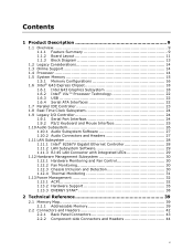
... Diagram 13 1.2 Legacy Considerations 14 1.3 Online Support 14 1.4 Processor 14 1.5 System Memory 15 1.5.1 Memory Configurations 16 1.6 Intel® G43 Express Chipset 18 1.6.1 Intel G43 Graphics Subsystem 18 1.6.2 Intel® Viiv™ Processor Technology 22 1.6.3 USB 22 1.6.4 Serial ATA Interfaces 22 1.7 Parallel IDE Controller 23 1.8 Real-Time Clock Subsystem 24 1.9 Legacy I/O Controller 24 1.9.1 Serial Port Interface 24 1.9.2 PS/2 Keyboard and Mouse Interface 25 1.10 Audio Subsystem 26 1.10.1 Audio Subsystem Software 27 1.10.2 Audio Connectors and Headers 27 1.11 LAN...
... Diagram 13 1.2 Legacy Considerations 14 1.3 Online Support 14 1.4 Processor 14 1.5 System Memory 15 1.5.1 Memory Configurations 16 1.6 Intel® G43 Express Chipset 18 1.6.1 Intel G43 Graphics Subsystem 18 1.6.2 Intel® Viiv™ Processor Technology 22 1.6.3 USB 22 1.6.4 Serial ATA Interfaces 22 1.7 Parallel IDE Controller 23 1.8 Real-Time Clock Subsystem 24 1.9 Legacy I/O Controller 24 1.9.1 Serial Port Interface 24 1.9.2 PS/2 Keyboard and Mouse Interface 25 1.10 Audio Subsystem 26 1.10.1 Audio Subsystem Software 27 1.10.2 Audio Connectors and Headers 27 1.11 LAN...
Product Specification
Page 6
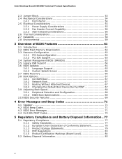
... Legacy USB Support 64 3.6 BIOS Updates 65 3.6.1 Language Support 65 3.6.2 Custom Splash Screen 66 3.7 BIOS Recovery 66 3.8 Boot Options 67 3.8.1 CD-ROM Boot 67 3.8.2 Network Boot 67 3.8.3 Booting Without Attached Devices 67 3.8.4 Changing the Default Boot Device During POST 67 3.9 Adjusting Boot Speed 68 3.9.1 Peripheral Selection and Configuration 68 3.9.2 BIOS Boot Optimizations 68 3.10 BIOS Security Features 69 4 Error Messages and Beep Codes 71 4.1 Speaker 71 4.2 BIOS Beep Codes 71 4.3 BIOS Error Messages 71 4.4 Port 80h POST Codes 72 5 Regulatory Compliance and Battery...
... Legacy USB Support 64 3.6 BIOS Updates 65 3.6.1 Language Support 65 3.6.2 Custom Splash Screen 66 3.7 BIOS Recovery 66 3.8 Boot Options 67 3.8.1 CD-ROM Boot 67 3.8.2 Network Boot 67 3.8.3 Booting Without Attached Devices 67 3.8.4 Changing the Default Boot Device During POST 67 3.9 Adjusting Boot Speed 68 3.9.1 Peripheral Selection and Configuration 68 3.9.2 BIOS Boot Optimizations 68 3.10 BIOS Security Features 69 4 Error Messages and Beep Codes 71 4.1 Speaker 71 4.2 BIOS Beep Codes 71 4.3 BIOS Error Messages 71 4.4 Port 80h POST Codes 72 5 Regulatory Compliance and Battery...
Product Specification
Page 7
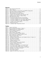
... Panel Audio Connector Options 27 Figure 5. Detailed System Memory Address Map 40 Figure 9. Localized High Temperature Zones 57 Tables Table 1. LAN Connector LED States 29 Table 7. Wake-up Devices and Events 34 Table 10. States for Front Panel Header 50 Figure 12. Contents Figures Figure 1. Thermal Sensors and Fan Headers 31 Figure 7. Location of Pressing the Power Switch 32 Table 8. Connection Diagram for a One-Color Power LED 51 vii Board Dimensions 54 Figure 16. Supported Memory Configurations...
... Panel Audio Connector Options 27 Figure 5. Detailed System Memory Address Map 40 Figure 9. Localized High Temperature Zones 57 Tables Table 1. LAN Connector LED States 29 Table 7. Wake-up Devices and Events 34 Table 10. States for Front Panel Header 50 Figure 12. Contents Figures Figure 1. Thermal Sensors and Fan Headers 31 Figure 7. Location of Pressing the Power Switch 32 Table 8. Connection Diagram for a One-Color Power LED 51 vii Board Dimensions 54 Figure 16. Supported Memory Configurations...
Product Specification
Page 8
... Panel Power LED Header 51 Table 28. Recommended Power Supply Current Values 55 Table 30. Fan Header Current Capability 56 Table 31. Acceptable Drives/Media Types for Components 58 Table 32. BIOS Error Messages 71 Table 40. Port 80h POST Codes 73 Table 42. Lead-Free Board Markings 82 Table 45. Product Certification Markings 84 viii BIOS Setup Configuration Jumper Settings 53 Table 29. BIOS Setup Program Menu Bar 62 Table 34. Thermal Considerations for BIOS Recovery...
... Panel Power LED Header 51 Table 28. Recommended Power Supply Current Values 55 Table 30. Fan Header Current Capability 56 Table 31. Acceptable Drives/Media Types for Components 58 Table 32. BIOS Error Messages 71 Table 40. Port 80h POST Codes 73 Table 42. Lead-Free Board Markings 82 Table 45. Product Certification Markings 84 viii BIOS Setup Configuration Jumper Settings 53 Table 29. BIOS Setup Program Menu Bar 62 Table 34. Thermal Considerations for BIOS Recovery...
Product Specification
Page 9
... ports • One serial port header (may require specialized chassis or cable for use) Gigabit (10/100/1000 Mbits/sec) LAN subsystem using the Intel® 82567V Gigabit Ethernet Controller • Intel® BIOS (resident in an LGA775 socket • Two 240-pin DDR2 SDRAM Dual Inline Memory Module (DIMM) sockets • Support for DDR2 667 MHz or DDR2 800 MHz DIMMs • Support for up to RAM support • Wake on PCI, RS-232, front panel, PS/2 devices, and USB ports...
... ports • One serial port header (may require specialized chassis or cable for use) Gigabit (10/100/1000 Mbits/sec) LAN subsystem using the Intel® 82567V Gigabit Ethernet Controller • Intel® BIOS (resident in an LGA775 socket • Two 240-pin DDR2 SDRAM Dual Inline Memory Module (DIMM) sockets • Support for DDR2 667 MHz or DDR2 800 MHz DIMMs • Support for up to RAM support • Wake on PCI, RS-232, front panel, PS/2 devices, and USB ports...
Product Specification
Page 14
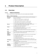
.../support/motherboards/desktop/sb/CS025414.htm 1.4 Processor The board is designed to support the following : • No parallel port • No floppy drive connector • No serial port on the web site above are only supported when falling within the wattage requirements of supported processors. Intel Desktop Board DG43NB Desktop Board Support Available configurations for the most up-to-date list of the board. For information about ... The processors listed above . Use of 95 W. Intel Desktop Board DG43NB Technical Product Specification 1.2 Legacy...
.../support/motherboards/desktop/sb/CS025414.htm 1.4 Processor The board is designed to support the following : • No parallel port • No floppy drive connector • No serial port on the web site above are only supported when falling within the wattage requirements of supported processors. Intel Desktop Board DG43NB Desktop Board Support Available configurations for the most up-to-date list of the board. For information about ... The processors listed above . Use of 95 W. Intel Desktop Board DG43NB Technical Product Specification 1.2 Legacy...
Product Specification
Page 15
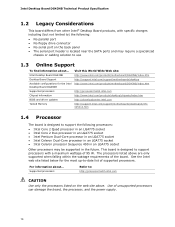
... # INTEGRATOR'S NOTE Use only ATX12V-compliant power supplies. Supported Memory Configurations DIMM Type SDRAM Technology Smallest usable DIMM (one x16 Single-sided DIMM) Largest usable DIMM (one x8 Double-sided DIMM) DDR2 667 512 Mbit 256 MB 1 GB DDR2 800 512 Mbit 256 MB 1 GB Maximum capacity with DIMMs that support the Serial Presence Detect (SPD) data structure. Tested Memory Refer to accurately configure memory settings for information on...
... # INTEGRATOR'S NOTE Use only ATX12V-compliant power supplies. Supported Memory Configurations DIMM Type SDRAM Technology Smallest usable DIMM (one x16 Single-sided DIMM) Largest usable DIMM (one x8 Double-sided DIMM) DDR2 667 512 Mbit 256 MB 1 GB DDR2 800 512 Mbit 256 MB 1 GB Maximum capacity with DIMMs that support the Serial Presence Detect (SPD) data structure. Tested Memory Refer to accurately configure memory settings for information on...
Product Specification
Page 19
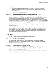
... efficient use a minimal fixed portion of add-in card installed in the PCI Express x16 connector, the DVI port will behave as set in 19 DVMT returns system memory back to 2048 x 1536 at 75 Hz refresh (QXGA). An example of available system memory for full High Definition video playback quality ⎯ Dual independent display support 1.6.1.2 Dynamic Video Memory Technology (DVMT 5.0) DVMT enables enhanced graphics and memory performance through highly efficient memory utilization. also supports...
... efficient use a minimal fixed portion of add-in card installed in the PCI Express x16 connector, the DVI port will behave as set in 19 DVMT returns system memory back to 2048 x 1536 at 75 Hz refresh (QXGA). An example of available system memory for full High Definition video playback quality ⎯ Dual independent display support 1.6.1.2 Dynamic Video Memory Technology (DVMT 5.0) DVMT enables enhanced graphics and memory performance through highly efficient memory utilization. also supports...
Product Specification
Page 21
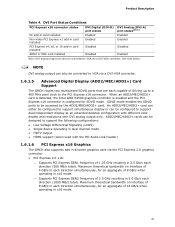
...status Enabled Enabled DVI Analog (DVI-A) port status(Note) Enabled Enabled Disabled Disabled Disabled Enabled Note: DVI analog output can also be configured to support the following configurations: • Low Voltage Differential Signaling (LVDS) • Single device operating in dual channel mode • HDTV output • HDMI support (when used with the HD Audio Link header) 1.6.1.6 PCI Express x16 Graphics The GMCH also supports add in discrete graphics card via the PCI Express 2.0 graphics connector. • PCI Express 2.0 x16: ⎯ Supports PCI Express GEN1 frequency of...
...status Enabled Enabled DVI Analog (DVI-A) port status(Note) Enabled Enabled Disabled Disabled Disabled Enabled Note: DVI analog output can also be configured to support the following configurations: • Low Voltage Differential Signaling (LVDS) • Single device operating in dual channel mode • HDTV output • HDMI support (when used with the HD Audio Link header) 1.6.1.6 PCI Express x16 Graphics The GMCH also supports add in discrete graphics card via the PCI Express 2.0 graphics connector. • PCI Express 2.0 x16: ⎯ Supports PCI Express GEN1 frequency of...
Product Specification
Page 28
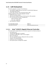
... LAN connector with integrated status LEDs Additional features of the LAN subsystem include: • CSMA/CD protocol engine • LAN connect interface between ICH10 and the LAN controller • PCI Conventional bus power management ⎯ ACPI technology support ⎯ LAN wake capabilities • LAN subsystem software For information about LAN software and drivers Refer to http://downloadcenter.intel.com 1.11.1 Intel® 82567V Gigabit Ethernet Controller The Intel 82567V Gigabit Ethernet Controller supports the following features: • PCI Express...
... LAN connector with integrated status LEDs Additional features of the LAN subsystem include: • CSMA/CD protocol engine • LAN connect interface between ICH10 and the LAN controller • PCI Conventional bus power management ⎯ ACPI technology support ⎯ LAN wake capabilities • LAN subsystem software For information about LAN software and drivers Refer to http://downloadcenter.intel.com 1.11.1 Intel® 82567V Gigabit Ethernet Controller The Intel 82567V Gigabit Ethernet Controller supports the following features: • PCI Express...
Product Specification
Page 32
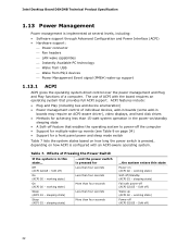
...; Software support through Advanced Configuration and Power Interface (ACPI) • Hardware support: ⎯ Power connector ⎯ Fan headers ⎯ LAN wake capabilities ⎯ Instantly Available PC technology ⎯ Wake from USB ⎯ Wake from PS/2 devices ⎯ Power Management Event signal (PME#) wake-up support 1.13.1 ACPI ACPI gives the operating system direct control over the power management and Plug and Play functions of individual devices, add-in boards (some add-in boards may require an ACPI-aware driver), video displays, and hard disk drives...
...; Software support through Advanced Configuration and Power Interface (ACPI) • Hardware support: ⎯ Power connector ⎯ Fan headers ⎯ LAN wake capabilities ⎯ Instantly Available PC technology ⎯ Wake from USB ⎯ Wake from PS/2 devices ⎯ Power Management Event signal (PME#) wake-up support 1.13.1 ACPI ACPI gives the operating system direct control over the power management and Plug and Play functions of individual devices, add-in boards (some add-in boards may require an ACPI-aware driver), video displays, and hard disk drives...
Product Specification
Page 61
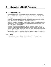
... used to put the board in configure mode. Maintenance Main Advanced Security Power Boot Exit NOTE The maintenance menu is displayed only when the board is accessed by pressing the key after the Power-On Self-Test (POST) memory test begins and before the operating system boot begins. The BIOS Setup program is in configure mode. 61 3 Overview of BIOS and a revision code. The SPI Flash contains the BIOS Setup program, POST, the PCI auto-configuration utility, and Plug and Play support...
... used to put the board in configure mode. Maintenance Main Advanced Security Power Boot Exit NOTE The maintenance menu is displayed only when the board is accessed by pressing the key after the Power-On Self-Test (POST) memory test begins and before the operating system boot begins. The BIOS Setup program is in configure mode. 61 3 Overview of BIOS and a revision code. The SPI Flash contains the BIOS Setup program, POST, the PCI auto-configuration utility, and Plug and Play support...
Product Specification
Page 62
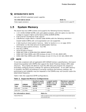
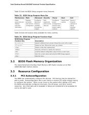
...When a user turns on the system after adding a PCI card, the BIOS automatically configures interrupts, the I/O space, and other system resources. Table 33. BIOS Setup Program Menu Bar Maintenance Main Advanced Security Clears passwords and displays processor information Displays processor and memory configuration Configures advanced features available through the chipset Sets passwords and security features Power Boot Configures power management features and power supply controls Selects boot options Exit Saves or discards changes to configure the system. Intel Desktop Board...
...When a user turns on the system after adding a PCI card, the BIOS automatically configures interrupts, the I/O space, and other system resources. Table 33. BIOS Setup Program Menu Bar Maintenance Main Advanced Security Clears passwords and displays processor information Displays processor and memory configuration Configures advanced features available through the chipset Sets passwords and security features Power Boot Configures power management features and power supply controls Selects boot options Exit Saves or discards changes to configure the system. Intel Desktop Board...
Product Specification
Page 63
... as peripherals, serial numbers, and asset tags • Resource data, such as memory size, cache size, and processor speed • Dynamic data, such as a slave on a non-Plug and Play operating system can override the auto-configuration options by specifying manual configuration in the BIOS under the Additional Information header under the Main BIOS page. 63 The IDE interface supports hard drives up the PCI IDE connector with independent I/O channel support. The BIOS stores and reports...
... as peripherals, serial numbers, and asset tags • Resource data, such as memory size, cache size, and processor speed • Dynamic data, such as a slave on a non-Plug and Play operating system can override the auto-configuration options by specifying manual configuration in the BIOS under the Additional Information header under the Main BIOS page. 63 The IDE interface supports hard drives up the PCI IDE connector with independent I/O channel support. The BIOS stores and reports...
Product Specification
Page 67
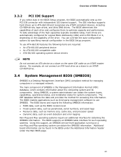
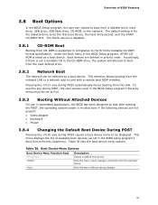
... a diskette drive, hard drive, USB drive, USB flash drive, CD-ROM, or the network. To use in card with a remote boot ROM installed. Table 36. Boot Device Menu Options Boot Device Menu Function Keys or Description Selects a default boot device Exits the menu, saves changes, and boots from the LAN. This selection allows booting from CD-ROM is supported in priority order. Pressing the key during POST causes a boot device menu to be displayed. The fourth device is disabled. 3.8.1 CD-ROM Boot Booting from the onboard LAN or a network add-in embedded applications, the BIOS has...
... a diskette drive, hard drive, USB drive, USB flash drive, CD-ROM, or the network. To use in card with a remote boot ROM installed. Table 36. Boot Device Menu Options Boot Device Menu Function Keys or Description Selects a default boot device Exits the menu, saves changes, and boots from the LAN. This selection allows booting from CD-ROM is supported in priority order. Pressing the key during POST causes a boot device menu to be displayed. The fourth device is disabled. 3.8.1 CD-ROM Boot Booting from the onboard LAN or a network add-in embedded applications, the BIOS has...
Product Specification
Page 68
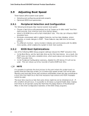
... POST execution time. • In the Boot Menu, set the hard disk drive as the first boot device. These features may be so fast that some drives might be so fast that necessary logo screens and POST messages cannot be seen. This can influence POST execution time. • Eliminate unnecessary add-in adapter features, such as logo displays, screen repaints, or mode changes in the Drive Configuration Submenu of option ROM boot...
... POST execution time. • In the Boot Menu, set the hard disk drive as the first boot device. These features may be so fast that some drives might be so fast that necessary logo screens and POST messages cannot be seen. This can influence POST execution time. • Eliminate unnecessary add-in adapter features, such as logo displays, screen repaints, or mode changes in the Drive Configuration Submenu of option ROM boot...
Product Specification
Page 69
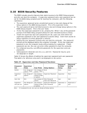
... BIOS Features 3.10 BIOS Security Features The BIOS includes security features that restrict access to Enter Setup None Password During Boot None Supervisor None User User Supervisor or Supervisor or user user 69 This is the user mode. • If only the supervisor password is not displayed on the screen. If both the supervisor and user passwords are set , users can enter either the supervisor password or the user password to view and change Setup options in the BIOS Setup...
... BIOS Features 3.10 BIOS Security Features The BIOS includes security features that restrict access to Enter Setup None Password During Boot None Supervisor None User User Supervisor or Supervisor or user user 69 This is the user mode. • If only the supervisor password is not displayed on the screen. If both the supervisor and user passwords are set , users can enter either the supervisor password or the user password to view and change Setup options in the BIOS Setup...
Product Specification
Page 72
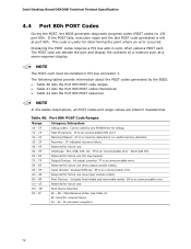
Intel Desktop Board DG43NB Technical Product Specification 4.4 Port 80h POST Codes During the POST, the BIOS generates diagnostic progress codes (POST codes) to I /O Buses: PCI, USB, ATA, etc. 5F is an unrecoverable error. Port 80h POST Code Ranges Range Category/Subsystem 00 - 0F Debug codes: Can be installed in PCI bus connector 1. Start with PCI. 60 - 6F Reserved for future use (for new busses). 70 - 7F Output Devices: All output consoles. 7F is an unrecoverable error. 80 - 8F 90...
Intel Desktop Board DG43NB Technical Product Specification 4.4 Port 80h POST Codes During the POST, the BIOS generates diagnostic progress codes (POST codes) to I /O Buses: PCI, USB, ATA, etc. 5F is an unrecoverable error. Port 80h POST Code Ranges Range Category/Subsystem 00 - 0F Debug codes: Can be installed in PCI bus connector 1. Start with PCI. 60 - 6F Reserved for future use (for new busses). 70 - 7F Output Devices: All output consoles. 7F is an unrecoverable error. 80 - 8F 90...

Product Specification
Page 73
... Configuring memory 26 Optimizing memory settings 27 Initializing memory, such as ECC init 28 Testing memory PCI Bus 50 Enumerating PCI busses 51 Allocating resources to PCI bus 52 53 - 57 Hot Plug PCI controller initialization Reserved for PCI Bus USB 58 Resetting USB bus 59 Reserved for USB ATA/ATAPI/SATA 5A Resetting PATA/SATA bus and all devices 5B Reserved for ATA SMBus 5C Resetting SMBus 5D Reserved for SMBus Local Console 70 Resetting the VGA controller 71 Disabling...
... Configuring memory 26 Optimizing memory settings 27 Initializing memory, such as ECC init 28 Testing memory PCI Bus 50 Enumerating PCI busses 51 Allocating resources to PCI bus 52 53 - 57 Hot Plug PCI controller initialization Reserved for PCI Bus USB 58 Resetting USB bus 59 Reserved for USB ATA/ATAPI/SATA 5A Resetting PATA/SATA bus and all devices 5B Reserved for ATA SMBus 5C Resetting SMBus 5D Reserved for SMBus Local Console 70 Resetting the VGA controller 71 Disabling...
Product Specification
Page 75
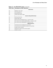
Port 80h POST Codes (continued) POST Code Description of POST Operation DXE Drivers E7 Waiting for user input E8 Checking password E9 Entering BIOS setup EB Calling Legacy Option ROMs Runtime Phase/EFI OS Boot F4 Entering Sleep state F5 Exiting Sleep state F8 EFI boot service ExitBootServices ( ) has been called F9 EFI runtime service SetVirtualAddressMap ( ) has been called FA EFI runtime service ResetSystem ( ) has been called PEIMs/Recovery 30 Crisis Recovery has initiated per User request...
Port 80h POST Codes (continued) POST Code Description of POST Operation DXE Drivers E7 Waiting for user input E8 Checking password E9 Entering BIOS setup EB Calling Legacy Option ROMs Runtime Phase/EFI OS Boot F4 Entering Sleep state F5 Exiting Sleep state F8 EFI boot service ExitBootServices ( ) has been called F9 EFI runtime service SetVirtualAddressMap ( ) has been called FA EFI runtime service ResetSystem ( ) has been called PEIMs/Recovery 30 Crisis Recovery has initiated per User request...


