Product Guide
Page 3
... Intel desktop boards are used in this manual: CAUTION Cautions warn the user about board layout, component installation, BIOS updates, and regulatory requirements for technically qualified personnel. may not be supported without further evaluation by Intel. Document Layout The chapters in this Product Guide are arranged as follows: 1 Desktop Board Features: a summary of product features 2 Installing and Replacing Desktop Board Components: instructions on how to update the BIOS 4 Configuring for RAID: information about configuring your system for installation...
... Intel desktop boards are used in this manual: CAUTION Cautions warn the user about board layout, component installation, BIOS updates, and regulatory requirements for technically qualified personnel. may not be supported without further evaluation by Intel. Document Layout The chapters in this Product Guide are arranged as follows: 1 Desktop Board Features: a summary of product features 2 Installing and Replacing Desktop Board Components: instructions on how to update the BIOS 4 Configuring for RAID: information about configuring your system for installation...
Product Guide
Page 4
... cable • One diskette drive cable • Four Serial ATA cables • One back panel USB 2.0 adapter • One 2x2 to some common terms used in the product guide. Intel Desktop Board D975XBX2 Product Guide Terminology The table below gives descriptions to 2x4 power supply cable adapter • Intel® Express Installer driver CD-ROM • Intel Express Installer software DVD-ROM • One diskette with the Intel® Matrix Storage RAID driver • One diskette with the Marvell* SATA Controller RAID driver • Back panel audio...
... cable • One diskette drive cable • Four Serial ATA cables • One back panel USB 2.0 adapter • One 2x2 to some common terms used in the product guide. Intel Desktop Board D975XBX2 Product Guide Terminology The table below gives descriptions to 2x4 power supply cable adapter • Intel® Express Installer driver CD-ROM • Intel Express Installer software DVD-ROM • One diskette with the Intel® Matrix Storage RAID driver • One diskette with the Marvell* SATA Controller RAID driver • Back panel audio...

Product Guide
Page 5
... 17 LAN Subsystem Software 17 RJ-45 LAN Connector LEDs 17 Hi-Speed USB 2.0 Support 18 Enhanced IDE Interface 18 Serial ATA...18 Expandability...18 BIOS ...19 Serial ATA and IDE Auto Configuration 19 PCI and PCI Express* Auto Configuration 19 Security Passwords 19 Chassis Intrusion 20 Power Management Features 20 ACPI ...20 Fan Connectors 20 Resume on Ring 22 Wake from USB 22 Wake from PS/2* Keyboard/Mouse 22 PME# Wakeup Support 22 Onboard Power Button 23 Speaker...23 Battery ...23 Real-Time Clock 23 2 Installing and Replacing Desktop Board...
... 17 LAN Subsystem Software 17 RJ-45 LAN Connector LEDs 17 Hi-Speed USB 2.0 Support 18 Enhanced IDE Interface 18 Serial ATA...18 Expandability...18 BIOS ...19 Serial ATA and IDE Auto Configuration 19 PCI and PCI Express* Auto Configuration 19 Security Passwords 19 Chassis Intrusion 20 Power Management Features 20 ACPI ...20 Fan Connectors 20 Resume on Ring 22 Wake from USB 22 Wake from PS/2* Keyboard/Mouse 22 PME# Wakeup Support 22 Onboard Power Button 23 Speaker...23 Battery ...23 Real-Time Clock 23 2 Installing and Replacing Desktop Board...
Product Guide
Page 6
... Configuration Jumper 52 Clearing Passwords 53 Back Panel Connectors 54 Replacing the Battery 55 3 BIOS Accessing the BIOS Setup Program 59 Updating the BIOS 59 Updating the BIOS with the Intel® Express BIOS Update Utility 59 Updating the BIOS with the Iflash Memory Update Utility 60 4 Configuring for RAID Requires Microsoft Windows* XP, Windows Vista*, or Windows 2000 and SATA Hard Drive(s) Configuring for RAID using Intel® Matrix Storage Technology 63 Configuring the BIOS 63 Creating Your RAID Set 63 Loading the Intel Matrix Storage Technology RAID Drivers and Software...
... Configuration Jumper 52 Clearing Passwords 53 Back Panel Connectors 54 Replacing the Battery 55 3 BIOS Accessing the BIOS Setup Program 59 Updating the BIOS 59 Updating the BIOS with the Intel® Express BIOS Update Utility 59 Updating the BIOS with the Iflash Memory Update Utility 60 4 Configuring for RAID Requires Microsoft Windows* XP, Windows Vista*, or Windows 2000 and SATA Hard Drive(s) Configuring for RAID using Intel® Matrix Storage Technology 63 Configuring the BIOS 63 Creating Your RAID Set 63 Loading the Intel Matrix Storage Technology RAID Drivers and Software...
Product Guide
Page 7
... Processor Fan Header ..........33 14. Use DDR2 DIMMs 36 18. Location of the BIOS Configuration Jumper Block 52 31. Location of Onboard Power Button 23 5. Location of Other Connectors 51 30. Remove the Processor from the Protective Processor Cover 31 11. Installing a PCI Express x16 Card 40 21. Dual Channel Memory Configuration Example 3 35 17. Back Panel Connectors 54 32. LAN Connector LEDs 17 3. Remove the Protective Socket Cover 31 10. Connecting the Rear Panel USB 2.0 Adapter 47 26. Close the Load Plate 32 13. Connecting the IDE Cable...
... Processor Fan Header ..........33 14. Use DDR2 DIMMs 36 18. Location of the BIOS Configuration Jumper Block 52 31. Location of Onboard Power Button 23 5. Location of Other Connectors 51 30. Remove the Processor from the Protective Processor Cover 31 11. Installing a PCI Express x16 Card 40 21. Dual Channel Memory Configuration Example 3 35 17. Back Panel Connectors 54 32. LAN Connector LEDs 17 3. Remove the Protective Socket Cover 31 10. Connecting the Rear Panel USB 2.0 Adapter 47 26. Close the Load Plate 32 13. Connecting the IDE Cable...

Product Guide
Page 10
... to RAM (STR) • Wake on USB, PCI, PCI Express, PS/2, LAN, and front panel Hardware Management Hardware monitor with: • Four fan sensing inputs used to monitor fan activity • Remote diode temperature sensing • Intel® Precision Cooling Technology fan speed control • Voltage sensing to detect out of range values Related Links For more information about Intel Desktop Board D975XBX2, including the Technical Product Specification (TPS), BIOS updates, and device drivers, go to: http://support.intel.com/support/motherboards/desktop...
... to RAM (STR) • Wake on USB, PCI, PCI Express, PS/2, LAN, and front panel Hardware Management Hardware monitor with: • Four fan sensing inputs used to monitor fan activity • Remote diode temperature sensing • Intel® Precision Cooling Technology fan speed control • Voltage sensing to detect out of range values Related Links For more information about Intel Desktop Board D975XBX2, including the Technical Product Specification (TPS), BIOS updates, and device drivers, go to: http://support.intel.com/support/motherboards/desktop...
Product Guide
Page 13
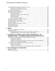
... DIMM 0 sockets Processor fan header (4-pin) DDR 2 DIMM 1 sockets Main power connector (2x12) Diskette drive connector BIOS configuration jumper Chassis intrusion header Onboard power button Battery IDE connector (right angle connector) 3.0-Gigabit/s Serial ATA connectors 0, 1, 2, and 3 (black) Front chassis fan header (3-pin) Alternate front panel power LED header (1x3) USB 2.0 headers (two ports per header) IEEE 1394a header 3.0-Gigabit/s Serial ATA connectors 5, 6, and 7 (blue) 3.0-Gigabit/s Serial ATA connector 4, compatible with external Serial ATA adapter (red) Front panel header Speaker...
... DIMM 0 sockets Processor fan header (4-pin) DDR 2 DIMM 1 sockets Main power connector (2x12) Diskette drive connector BIOS configuration jumper Chassis intrusion header Onboard power button Battery IDE connector (right angle connector) 3.0-Gigabit/s Serial ATA connectors 0, 1, 2, and 3 (black) Front chassis fan header (3-pin) Alternate front panel power LED header (1x3) USB 2.0 headers (two ports per header) IEEE 1394a header 3.0-Gigabit/s Serial ATA connectors 5, 6, and 7 (blue) 3.0-Gigabit/s Serial ATA connector 4, compatible with external Serial ATA adapter (red) Front panel header Speaker...
Product Guide
Page 14
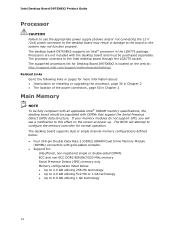
... on the screen at : http://support.intel.com/support/motherboards/desktop/ Related Links Go to 8.0 GB utilizing 1 Gb technology 14 Intel Desktop Board D975XBX2 Product Guide Processor CAUTION Failure to use the appropriate power supply (below) and/or not connecting the 12 V (2x4) power connector to the desktop board may not function properly. The desktop board D975XBX2 supports an Intel® processor in Chapter 2 Main Memory NOTE To be fully compliant with all applicable Intel® SDRAM memory specifications, the desktop board should be...
... on the screen at : http://support.intel.com/support/motherboards/desktop/ Related Links Go to 8.0 GB utilizing 1 Gb technology 14 Intel Desktop Board D975XBX2 Product Guide Processor CAUTION Failure to use the appropriate power supply (below) and/or not connecting the 12 V (2x4) power connector to the desktop board may not function properly. The desktop board D975XBX2 supports an Intel® processor in Chapter 2 Main Memory NOTE To be fully compliant with all applicable Intel® SDRAM memory specifications, the desktop board should be...
Product Guide
Page 18
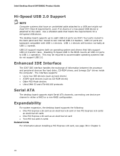
... x16 card or two PCI Express x16 cards as electrical x8 cards • One PCI Express x16 card as CD-ROM drives) • Older PIO Mode devices • Ultra DMA-33 and ATA-66/100 protocols Serial ATA The desktop board supports eight Serial ATA channels, connecting one device per channel in either a RAID or a non-RAID configuration. USB 2.0 support requires both an operating system and drivers that meets the requirements for a full-speed USB device. Intel Desktop Board D975XBX2 Product Guide Hi-Speed USB 2.0 Support NOTE...
... x16 card or two PCI Express x16 cards as electrical x8 cards • One PCI Express x16 card as CD-ROM drives) • Older PIO Mode devices • Ultra DMA-33 and ATA-66/100 protocols Serial ATA The desktop board supports eight Serial ATA channels, connecting one device per channel in either a RAID or a non-RAID configuration. USB 2.0 support requires both an operating system and drivers that meets the requirements for a full-speed USB device. Intel Desktop Board D975XBX2 Product Guide Hi-Speed USB 2.0 Support NOTE...
Product Guide
Page 19
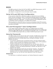
... Setup gives the user restricted access to Setup. • If both passwords are set , you connect a Serial ATA or IDE device (such as a hard drive) to run the BIOS Setup program after installing a Serial ATA or IDE device. You do not need to your desktop board, the PCI/PCI Express auto-configuration utility in the BIOS automatically detects and configures the resources (IRQs, DMA channels, and I/O space) for a password. The password prompt is displayed before the computer is the last boot device by specifying manual configuration...
... Setup gives the user restricted access to Setup. • If both passwords are set , you connect a Serial ATA or IDE device (such as a hard drive) to run the BIOS Setup program after installing a Serial ATA or IDE device. You do not need to your desktop board, the PCI/PCI Express auto-configuration utility in the BIOS automatically detects and configures the resources (IRQs, DMA channels, and I/O space) for a password. The password prompt is displayed before the computer is the last boot device by specifying manual configuration...
Product Guide
Page 20
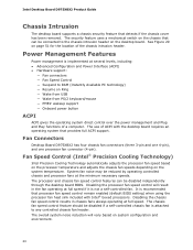
... processor fan speed control remain enabled (default BIOS setting) when using the processor fan heat sink included with Intel® boxed processors. Disabling the chassis fan speed control results in the fan operating at the minimum necessary speeds. Fan Connectors Desktop Board D975XBX2 has four chassis fan connectors (three 3-pin and one 4-pin), and one processor fan connector (4-pin). The overall system noise reduction will result in chassis fans always operating at several levels, including: • Advanced Configuration and Power Interface (ACPI) • Hardware support...
... processor fan speed control remain enabled (default BIOS setting) when using the processor fan heat sink included with Intel® boxed processors. Disabling the chassis fan speed control results in the fan operating at the minimum necessary speeds. Fan Connectors Desktop Board D975XBX2 has four chassis fan connectors (three 3-pin and one 4-pin), and one processor fan connector (4-pin). The overall system noise reduction will result in chassis fans always operating at several levels, including: • Advanced Configuration and Power Interface (ACPI) • Hardware support...
Product Guide
Page 21
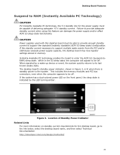
... to be off . The desktop board's standby power indicator, shown in memory. Location of delivering adequate +5 V standby current. When signaled by the LED turning amber. CAUTION Power supplies used with this feature can damage the power supply and/or affect ACPI S3 sleep state functionality. This includes the memory modules and PCI bus connectors, even when the computer appears to RAM (Instantly Available PC Technology) CAUTION For Instantly Available PC...
... to be off . The desktop board's standby power indicator, shown in memory. Location of delivering adequate +5 V standby current. When signaled by the LED turning amber. CAUTION Power supplies used with this feature can damage the power supply and/or affect ACPI S3 sleep state functionality. This includes the memory modules and PCI bus connectors, even when the computer appears to RAM (Instantly Available PC Technology) CAUTION For Instantly Available PC...

Product Guide
Page 23
... 2 starting on page 25 for instructions on the desktop board keeps the values in this section only at integration facilities to remove standby power before making changes to replace the battery. Location of the computer chassis. Battery A battery on how to the system configuration, or for testing purposes. Figure 4. The battery on the desktop board. This button is turned off . The speaker provides audible error code (beep code) information during the Power-On Self-Test (POST...
... 2 starting on page 25 for instructions on the desktop board keeps the values in this section only at integration facilities to remove standby power before making changes to replace the battery. Location of the computer chassis. Battery A battery on how to the system configuration, or for testing purposes. Figure 4. The battery on the desktop board. This button is turned off . The speaker provides audible error code (beep code) information during the Power-On Self-Test (POST...
Product Guide
Page 25
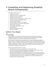
...tells you how to: • Install the I/O shield • Install and remove the desktop board • Install and remove a processor • Install and remove memory • Install and remove a PCI Express x16 add-in card • Connect the IDE and Serial ATA cables • Connect internal headers • Install USB/external Serial ATA adapters • Connect chassis fan and power supply cables • Identify other connectors • Set the BIOS configuration jumper • Clear passwords • Identify back panel connectors • Replace the battery Before You Begin CAUTIONS The...
...tells you how to: • Install the I/O shield • Install and remove the desktop board • Install and remove a processor • Install and remove memory • Install and remove a PCI Express x16 add-in card • Connect the IDE and Serial ATA cables • Connect internal headers • Install USB/external Serial ATA adapters • Connect chassis fan and power supply cables • Identify other connectors • Set the BIOS configuration jumper • Clear passwords • Identify back panel connectors • Replace the battery Before You Begin CAUTIONS The...
Product Guide
Page 52
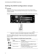
... 9 shows the jumper settings for booting. The BIOS recovers data from the computer before changing the jumper. Location of a failed BIOS update. 52 Figure 30 shows the location of the desktop board's BIOS configuration jumper block. Jumper Settings for the BIOS Setup Program Modes Jumper Setting Mode Normal (default) (1-2) Description The BIOS uses the current configuration and passwords for the Setup program modes. Configure (2-3) Recovery (None) After the Power-On Self-Test (POST) runs, the BIOS displays the Maintenance Menu. Moving the jumper with the power on may result...
... 9 shows the jumper settings for booting. The BIOS recovers data from the computer before changing the jumper. Location of a failed BIOS update. 52 Figure 30 shows the location of the desktop board's BIOS configuration jumper block. Jumper Settings for the BIOS Setup Program Modes Jumper Setting Mode Normal (default) (1-2) Description The BIOS uses the current configuration and passwords for the Setup program modes. Configure (2-3) Recovery (None) After the Power-On Self-Test (POST) runs, the BIOS displays the Maintenance Menu. Moving the jumper with the power on may result...

Product Guide
Page 53
... or power adapter). 3. Find the configuration jumper block (see Figure 30). 5. Setup displays the Maintenance menu. 8. Press and Setup displays a pop-up screen requesting that the board is installed in the computer and the configuration jumper block is set to select Clear Passwords. Replace the cover, plug in the computer, turn it to boot. 7. Setup displays the maintenance menu again. 9. Installing and Replacing Desktop Board Components Clearing Passwords This procedure assumes that you confirm clearing the password. The computer starts the Setup program. Use...
... or power adapter). 3. Find the configuration jumper block (see Figure 30). 5. Setup displays the Maintenance menu. 8. Press and Setup displays a pop-up screen requesting that the board is installed in the computer and the configuration jumper block is set to select Clear Passwords. Replace the cover, plug in the computer, turn it to boot. 7. Setup displays the maintenance menu again. 9. Installing and Replacing Desktop Board Components Clearing Passwords This procedure assumes that you confirm clearing the password. The computer starts the Setup program. Use...
Product Guide
Page 59
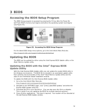
... BIOS updates," and select the Express BIOS Update utility file. 3. Accessing the BIOS Setup Program For the latest BIOS Setup menu options, go to the Intel World Wide Web site: http://support.intel.com/support/motherboards/desktop/ Updating the BIOS The BIOS can also save this file to your hard drive. (You can be rebooted at the last Express BIOS Update window. 59 To update the BIOS with the Intel® Express BIOS Update Utility With the Intel Express BIOS Update utility you are updating the BIOS for multiple identical systems.) 4. This step is useful...
... BIOS updates," and select the Express BIOS Update utility file. 3. Accessing the BIOS Setup Program For the latest BIOS Setup menu options, go to the Intel World Wide Web site: http://support.intel.com/support/motherboards/desktop/ Updating the BIOS The BIOS can also save this file to your hard drive. (You can be rebooted at the last Express BIOS Update window. 59 To update the BIOS with the Intel® Express BIOS Update Utility With the Intel Express BIOS Update utility you are updating the BIOS for multiple identical systems.) 4. This step is useful...
Product Guide
Page 60
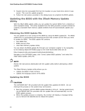
... version of the BIOS Updating the BIOS CAUTION The AUTOEXEC.BAT file provided with the update utility before attempting a BIOS update. Intel Desktop Board D975XBX2 Product Guide 5. The utility available from the Web provides a simple method for creating a bootable flash memory update diskette that contains all the files you can update the system BIOS from the location on the Intel World Wide Web site at: http://support.intel.com/support/motherboards/desktop Navigate to : • Update the BIOS in flash memory...
... version of the BIOS Updating the BIOS CAUTION The AUTOEXEC.BAT file provided with the update utility before attempting a BIOS update. Intel Desktop Board D975XBX2 Product Guide 5. The utility available from the Web provides a simple method for creating a bootable flash memory update diskette that contains all the files you can update the system BIOS from the location on the Intel World Wide Web site at: http://support.intel.com/support/motherboards/desktop Navigate to : • Update the BIOS in flash memory...
Product Guide
Page 64
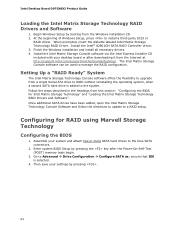
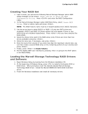
Install the Intel® 82801GH SATA RAID Controller driver. 3. Assemble your system and attach two or more SATA hard drives to manage the RAID configuration. Then save your desktop board or after the Power-On-Self-Test (POST) memory tests begin. 3. The Intel Matrix Storage Console software can be used to the blue SATA connectors. 2. Intel Desktop Board D975XBX2 Product Guide Loading the Intel Matrix Storage Technology RAID Drivers and Software 1. Begin Windows Setup by booting from this section: "Configuring the BIOS for RAID using Marvell Storage Technology Configuring the BIOS...
Install the Intel® 82801GH SATA RAID Controller driver. 3. Assemble your system and attach two or more SATA hard drives to manage the RAID configuration. Then save your desktop board or after the Power-On-Self-Test (POST) memory tests begin. 3. The Intel Matrix Storage Console software can be used to the blue SATA connectors. 2. Intel Desktop Board D975XBX2 Product Guide Loading the Intel Matrix Storage Technology RAID Drivers and Software 1. Begin Windows Setup by booting from this section: "Configuring the BIOS for RAID using Marvell Storage Technology Configuring the BIOS...
Product Guide
Page 65
... to enter the RAID Configuration Utility. Install the Marvell 88SE61XX SATA RAID Controller driver. 3. Configuring for RAID Creating Your RAID Set 1. Select the drives to the EXIT option in English alphanumeric ASCII characters. 3. Press once you can then create a second RAID array on the screen: Press to Create Volume. 8. Enter a volume name and press . Exit the Option ROM user interface by booting from the Windows installation CD. 2. When prompted, insert the diskette labeled Marvell Storage Technology RAID Driver...
... to enter the RAID Configuration Utility. Install the Marvell 88SE61XX SATA RAID Controller driver. 3. Configuring for RAID Creating Your RAID Set 1. Select the drives to the EXIT option in English alphanumeric ASCII characters. 3. Press once you can then create a second RAID array on the screen: Press to Create Volume. 8. Enter a volume name and press . Exit the Option ROM user interface by booting from the Windows installation CD. 2. When prompted, insert the diskette labeled Marvell Storage Technology RAID Driver...


