Product Specification
Page 5
...Summary 9 1.1.2 Board Layout 11 1.1.3 Block Diagram 13 1.2 Legacy Considerations 14 1.3 Online Support 14 1.4 Processor 14 1.5 System Memory 15 1.6 Intel® 945GC Chipset 16 1.6.1 Intel 945GC Graphics Subsystem 16 1.6.2 USB 18 1.6.3 IDE Support 18 1.7 Real-Time Clock Subsystem 19 1.8 S-Video Output 20 1.9 ...Management 28 1.13.1 ACPI 28 1.13.2 Hardware Support 31 1.13.3 ENERGY STAR 35 2 Technical Reference 2.1 Memory Map 37 2.1.1 Addressable Memory 37 2.2 Connectors and Headers 40 2.2.1 Back Panel Connectors 41 2.2.2 Component-side Connectors and Headers 42 2.3 Jumper ...
...Summary 9 1.1.2 Board Layout 11 1.1.3 Block Diagram 13 1.2 Legacy Considerations 14 1.3 Online Support 14 1.4 Processor 14 1.5 System Memory 15 1.6 Intel® 945GC Chipset 16 1.6.1 Intel 945GC Graphics Subsystem 16 1.6.2 USB 18 1.6.3 IDE Support 18 1.7 Real-Time Clock Subsystem 19 1.8 S-Video Output 20 1.9 ...Management 28 1.13.1 ACPI 28 1.13.2 Hardware Support 31 1.13.3 ENERGY STAR 35 2 Technical Reference 2.1 Memory Map 37 2.1.1 Addressable Memory 37 2.2 Connectors and Headers 40 2.2.1 Back Panel Connectors 41 2.2.2 Component-side Connectors and Headers 42 2.3 Jumper ...
Product Specification
Page 6
Intel Desktop Board D945GCLF2 Technical Product Specification 2.5.1 Power Supply Considerations 51 2.5.2 Fan Header Current Capability 51 2.5.3 Add-in Board Considerations 52 2.6 Thermal Considerations 52 2.7 Reliability 54 2.8 Environmental 54 3 Overview of BIOS Features 3.1 Introduction 55 3.2 BIOS Flash Memory Organization 56 3.3 Resource Configuration 56 3.3.1 PCI* Autoconfiguration 56 3.4 System Management BIOS (SMBIOS 57 3.5 Legacy USB Support...
Intel Desktop Board D945GCLF2 Technical Product Specification 2.5.1 Power Supply Considerations 51 2.5.2 Fan Header Current Capability 51 2.5.3 Add-in Board Considerations 52 2.6 Thermal Considerations 52 2.7 Reliability 54 2.8 Environmental 54 3 Overview of BIOS Features 3.1 Introduction 55 3.2 BIOS Flash Memory Organization 56 3.3 Resource Configuration 56 3.3.1 PCI* Autoconfiguration 56 3.4 System Management BIOS (SMBIOS 57 3.5 Legacy USB Support...
Product Specification
Page 7
... Considerations for Front Panel Header 46 11. BIOS Setup Program Menu Bar 56 27. Back Panel Audio Connectors 23 4. LAN Connector LED States 25 6. System Memory Map 39 10. GMCH (3-Pin) Fan Header 44 15. Component-side Connectors and Headers 42 10. ATX12V Power Connector 46 18. Front Panel Header 46... 6. Feature Summary 9 2. Board Components Shown in Figure 9 43 11. Serial ATA Connectors 44 13. Main Power Connector 45 17. Fan Header Current Capability 51 24. Intel Desktop Board D945GCLF2 Environmental Specifications 54 26.
... Considerations for Front Panel Header 46 11. BIOS Setup Program Menu Bar 56 27. Back Panel Audio Connectors 23 4. LAN Connector LED States 25 6. System Memory Map 39 10. GMCH (3-Pin) Fan Header 44 15. Component-side Connectors and Headers 42 10. ATX12V Power Connector 46 18. Front Panel Header 46... 6. Feature Summary 9 2. Board Components Shown in Figure 9 43 11. Serial ATA Connectors 44 13. Main Power Connector 45 17. Fan Header Current Capability 51 24. Intel Desktop Board D945GCLF2 Environmental Specifications 54 26.
Product Specification
Page 9
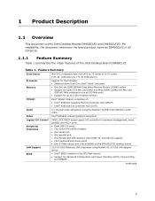
...240-pin DDR2 SDRAM Dual Inline Memory Module (DIMM) socket • Support for DDR2 533 MHz and DDR2 400 MHz DIMMs (DDR2 800 MHz and DDR 667 MHz validated to run at 533 MHz only) • Support for up to 2 GB of system memory Intel® 945GC Chipset, consisting ...of: • Intel® 82945GC Graphics Memory Controller Hub (GMCH) • Intel® 82801GB I/O Controller Hub (ICH7) Audio Video Legacy I/O Control Peripheral Interfaces LAN Support BIOS 5.1-channel...
...240-pin DDR2 SDRAM Dual Inline Memory Module (DIMM) socket • Support for DDR2 533 MHz and DDR2 400 MHz DIMMs (DDR2 800 MHz and DDR 667 MHz validated to run at 533 MHz only) • Support for up to 2 GB of system memory Intel® 945GC Chipset, consisting ...of: • Intel® 82945GC Graphics Memory Controller Hub (GMCH) • Intel® 82801GB I/O Controller Hub (ICH7) Audio Video Legacy I/O Control Peripheral Interfaces LAN Support BIOS 5.1-channel...

Product Specification
Page 15
...or double-sided DIMMs with the following restriction: Double-sided DIMMs with x16 organization are not supported. • 2 GB maximum total system memory • Minimum total system memory: 128 MB • Non-ECC DIMMs • Serial Presence Detect • DDR2 533 MHz or DDR2 400 MHz SDRAM DIMMs (... should be impacted or the DIMMs may not function under the determined frequency. Product Description 1.5 System Memory The board has one row of SDRAM) and "SS" refers to : http://support.intel.com/support/motherboards/desktop/sb/ CS-025414.htm 15 This allows the BIOS to read the SPD data...
...or double-sided DIMMs with the following restriction: Double-sided DIMMs with x16 organization are not supported. • 2 GB maximum total system memory • Minimum total system memory: 128 MB • Non-ECC DIMMs • Serial Presence Detect • DDR2 533 MHz or DDR2 400 MHz SDRAM DIMMs (... should be impacted or the DIMMs may not function under the determined frequency. Product Description 1.5 System Memory The board has one row of SDRAM) and "SS" refers to : http://support.intel.com/support/motherboards/desktop/sb/ CS-025414.htm 15 This allows the BIOS to read the SPD data...
Product Specification
Page 16
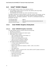
...Intel 945GC Graphics Subsystem 1.6.1.1 Intel® GMA950 Graphics Controller The Intel GMA950 graphics controller features the following devices: • Intel 82945GC Graphics Memory Controller Hub (GMCH) with Direct Media Interface (DMI) interconnect • Intel 82801GB I /O paths. Intel Desktop Board D945GCLF2 Technical Product Specification 1.6 Intel® 945GC Chipset The Intel... ⎯ Anti-aliased lines 16 For information about The Intel 945GC chipset Resources used by the chipset Refer to the CPU, memory, PCI Express, and the DMI interconnect. The component also...
...Intel 945GC Graphics Subsystem 1.6.1.1 Intel® GMA950 Graphics Controller The Intel GMA950 graphics controller features the following devices: • Intel 82945GC Graphics Memory Controller Hub (GMCH) with Direct Media Interface (DMI) interconnect • Intel 82801GB I /O paths. Intel Desktop Board D945GCLF2 Technical Product Specification 1.6 Intel® 945GC Chipset The Intel... ⎯ Anti-aliased lines 16 For information about The Intel 945GC chipset Resources used by the chipset Refer to the CPU, memory, PCI Express, and the DMI interconnect. The component also...

Product Specification
Page 17
... to 128 MB can be allocated to DVMT when less than 512 MB of system memory is installed. NOTE The use of supported modes for the Intel GMA950 graphics controller is no longer required by the graphics subsystem. For information about Obtaining graphics software and utilities Refer to Section ... 24-bit 400 MHz RAMDAC ⎯ Up to 2048 x 1536 at 75 Hz refresh (QXGA) • Dynamic Video Memory Technology (DVMT) support up to 224 MB • Intel® Zoom Utility For information about Supported video modes for the board Refer to Section 1.2, page 14 17 DVMT returns system...
... to 128 MB can be allocated to DVMT when less than 512 MB of system memory is installed. NOTE The use of supported modes for the Intel GMA950 graphics controller is no longer required by the graphics subsystem. For information about Obtaining graphics software and utilities Refer to Section ... 24-bit 400 MHz RAMDAC ⎯ Up to 2048 x 1536 at 75 Hz refresh (QXGA) • Dynamic Video Memory Technology (DVMT) support up to 224 MB • Intel® Zoom Utility For information about Supported video modes for the board Refer to Section 1.2, page 14 17 DVMT returns system...
Product Specification
Page 19
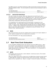
... plugged in CMOS RAM (for host to Figure 9, page 42 1.7 Real-Time Clock Subsystem A coin-cell battery (CR2032) powers the real-time clock and CMOS memory. Figure 1 on each port for configurations using the Windows* XP and Windows Vista* operating systems. NOTE Many Serial ATA drives use new low-voltage power...
... plugged in CMOS RAM (for host to Figure 9, page 42 1.7 Real-Time Clock Subsystem A coin-cell battery (CR2032) powers the real-time clock and CMOS memory. Figure 1 on each port for configurations using the Windows* XP and Windows Vista* operating systems. NOTE Many Serial ATA drives use new low-voltage power...
Product Specification
Page 37
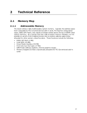
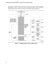
...all of DRAM (total system memory). Typically the address space that is allocated for PCI Conventional bus add-in cards, PCI Express configuration space, BIOS (SPI Flash), and chipset overhead resides above the top of the installed memory due to system address space being... allocated for PCI Conventional add-in cards 37 2 Technical Reference 2.1 Memory Map 2.1.1 Addressable Memory The board utilizes 2 GB of addressable system memory. These functions include the following: • BIOS/ SPI Flash (4 MB) • Local APIC (19 MB) • Direct Media Interface ...
...all of DRAM (total system memory). Typically the address space that is allocated for PCI Conventional bus add-in cards, PCI Express configuration space, BIOS (SPI Flash), and chipset overhead resides above the top of the installed memory due to system address space being... allocated for PCI Conventional add-in cards 37 2 Technical Reference 2.1 Memory Map 2.1.1 Addressable Memory The board utilizes 2 GB of addressable system memory. These functions include the following: • BIOS/ SPI Flash (4 MB) • Local APIC (19 MB) • Direct Media Interface ...
Product Specification
Page 38
Figure 7 shows a schematic of system addresses. Figure 7. All installed system memory can be used will vary based on add-in cards and BIOS settings. Detailed System Memory Address Map 38 Intel Desktop Board D945GCLF2 Technical Product Specification The amount of installed memory that can be used when there is no overlap of the system memory map.
Figure 7 shows a schematic of system addresses. Figure 7. All installed system memory can be used will vary based on add-in cards and BIOS settings. Detailed System Memory Address Map 38 Intel Desktop Board D945GCLF2 Technical Product Specification The amount of installed memory that can be used when there is no overlap of the system memory map.
Product Specification
Page 39
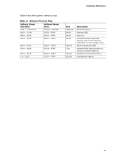
... Table 9. Dependent on video adapter used. FFFFF 896 K - 960 K 800 K - 896 K E0000 - DFFFF 640 K - 800 K 639 K - 640 K 512 K - 639 K 0 K - 512 K A0000 - System Memory Map Address Range (decimal) Address Range (hex) 1024 K - 2097152 K 100000 - FFFFFFFF 960 K - 1024 K F0000 - C7FFF 9FC00 - 9FFFF 80000 - 9FBFF 00000 - 7FFFF Size 2048 MB 64 ...KB 64 KB 96 KB 160 KB 1 KB 127 KB 512 KB Description Extended memory Runtime BIOS Reserved Potential available high DOS memory (open to the PCI bus).
... Table 9. Dependent on video adapter used. FFFFF 896 K - 960 K 800 K - 896 K E0000 - DFFFF 640 K - 800 K 639 K - 640 K 512 K - 639 K 0 K - 512 K A0000 - System Memory Map Address Range (decimal) Address Range (hex) 1024 K - 2097152 K 100000 - FFFFFFFF 960 K - 1024 K F0000 - C7FFF 9FC00 - 9FFFF 80000 - 9FBFF 00000 - 7FFFF Size 2048 MB 64 ...KB 64 KB 96 KB 160 KB 1 KB 127 KB 512 KB Description Extended memory Runtime BIOS Reserved Potential available high DOS memory (open to the PCI bus).

Product Specification
Page 55
.... The BIOS displays a message during POST identifying the type of BIOS Features 3.1 Introduction The board uses an Intel BIOS that is set to put the board in the Serial Peripheral Interface Flash Memory (SPI Flash) and can be updated using a disk-based program. The initial production BIOSs are identified as... EEPROM information, and Plug and Play support. The menu bar is accessed by pressing the key after the Power-On Self-Test (POST) memory test begins and before the operating system boot begins. The BIOS Setup program can be used to view and change the BIOS settings for the...
.... The BIOS displays a message during POST identifying the type of BIOS Features 3.1 Introduction The board uses an Intel BIOS that is set to put the board in the Serial Peripheral Interface Flash Memory (SPI Flash) and can be updated using a disk-based program. The initial production BIOSs are identified as... EEPROM information, and Plug and Play support. The menu bar is accessed by pressing the key after the Power-On Self-Test (POST) memory test begins and before the operating system boot begins. The BIOS Setup program can be used to view and change the BIOS settings for the...
Product Specification
Page 56
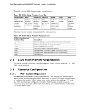
Intel Desktop Board D945GCLF2 Technical Product Specification Table 26 lists the BIOS Setup program menu features. PCI devices may be available for use by the add-... The BIOS can automatically configure PCI devices. BIOS Setup Program Menu Bar Maintenance Main Advanced Security Clears passwords and displays processor information Displays processor and memory configuration Configures advanced features available through the chipset Sets passwords and security features Power Boot Configures power management features and power supply controls Selects boot...
Intel Desktop Board D945GCLF2 Technical Product Specification Table 26 lists the BIOS Setup program menu features. PCI devices may be available for use by the add-... The BIOS can automatically configure PCI devices. BIOS Setup Program Menu Bar Maintenance Main Advanced Security Clears passwords and displays processor information Displays processor and memory configuration Configures advanced features available through the chipset Sets passwords and security features Power Boot Configures power management features and power supply controls Selects boot...
Product Specification
Page 57
...; BIOS data, such as the BIOS revision level • Fixed-system data, such as peripherals, serial numbers, and asset tags • Resource data, such as memory size, cache size, and processor speed • Dynamic data, such as third-party management software to use SMBIOS.
...; BIOS data, such as the BIOS revision level • Fixed-system data, such as peripherals, serial numbers, and asset tags • Resource data, such as memory size, cache size, and processor speed • Dynamic data, such as third-party management software to use SMBIOS.
Product Specification
Page 59
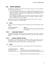
... Language Support The BIOS Setup program and help messages are supported in US English. This splash screen can be updated from DOS. The Intel® Integrator's Toolkit that the updated BIOS matches the target system to create a custom splash screen. Both utilities verify that is displayed ... USB hard drive), or a CD-ROM, or from the file location on the Web. • Intel® Flash Memory Update Utility, which requires booting from a file on the Intel World Wide Web site: • Intel® Express BIOS Update utility, which are available on a hard disk, a USB drive (a flash ...
... Language Support The BIOS Setup program and help messages are supported in US English. This splash screen can be updated from DOS. The Intel® Integrator's Toolkit that the updated BIOS matches the target system to create a custom splash screen. Both utilities verify that is displayed ... USB hard drive), or a CD-ROM, or from the file location on the Web. • Intel® Flash Memory Update Utility, which requires booting from a file on the Intel World Wide Web site: • Intel® Express BIOS Update utility, which are available on a hard disk, a USB drive (a flash ...
Product Specification
Page 65
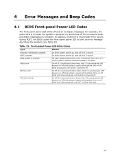
... off and on to blink an error message describing the problem (see Table 32). Table 31. pattern repeats until system is powered off blink pattern; Memory error On-off (0.5 second each) three times, then 3.0 second pause (off) between on -off blinks and 3-second pause) until BIOS update is complete. In addition...
... off and on to blink an error message describing the problem (see Table 32). Table 31. pattern repeats until system is powered off blink pattern; Memory error On-off (0.5 second each) three times, then 3.0 second pause (off) between on -off blinks and 3-second pause) until BIOS update is complete. In addition...
Product Specification
Page 66
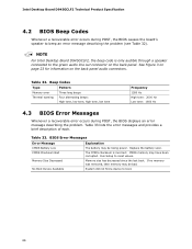
Intel Desktop Board D945GCLF2 Technical Product Specification 4.2 BIOS Beep Codes Whenever a recoverable error ...Table 33. BIOS Error Messages Error Message Explanation CMOS Battery Low CMOS Checksum Bad The battery may be bad. CMOS memory may be losing power. No Boot Device Available System did not find a device to beep an error message describing...the board's speaker to boot. 66 See Figure 3 on page 23 for information on the back panel. Memory Size Decreased Memory size has decreased since the last boot. Run Setup to the green audio line out connector on the back...
Intel Desktop Board D945GCLF2 Technical Product Specification 4.2 BIOS Beep Codes Whenever a recoverable error ...Table 33. BIOS Error Messages Error Message Explanation CMOS Battery Low CMOS Checksum Bad The battery may be bad. CMOS memory may be losing power. No Boot Device Available System did not find a device to beep an error message describing...the board's speaker to boot. 66 See Figure 3 on page 23 for information on the back panel. Memory Size Decreased Memory size has decreased since the last boot. Run Setup to the green audio line out connector on the back...
Product Specification
Page 67
... a POST card. C0 - EE: Miscellaneous codes. Reserved for debug. 10 - 1F Host Processors: 1F is an unrecoverable CPU error. 20 - 2F Memory/Chipset: 2F is no memory detected or no useful memory detected. 30 - 3F 40 - 4F Recovery: 3F indicated recovery failure. BF Reserved for future use . 50 - 5F I /O port 80h. Boot Devices...
... a POST card. C0 - EE: Miscellaneous codes. Reserved for debug. 10 - 1F Host Processors: 1F is an unrecoverable CPU error. 20 - 2F Memory/Chipset: 2F is no memory detected or no useful memory detected. 30 - 3F 40 - 4F Recovery: 3F indicated recovery failure. BF Reserved for future use . 50 - 5F I /O port 80h. Boot Devices...
Product Specification
Page 68
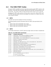
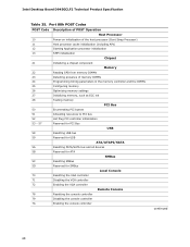
Intel Desktop Board D945GCLF2 Technical Product Specification Table 35. Port 80h POST Codes POST Code Description of POST Operation Host Processor 10 Power-on initialization of ... 13 SMM initialization Chipset 21 Initializing a chipset component Memory 22 Reading SPD from memory DIMMs 23 Detecting presence of memory DIMMs 24 Programming timing parameters in the memory controller and the DIMMs 25 Configuring memory 26 Optimizing memory settings 27 Initializing memory, such as ECC init 28 Testing memory PCI Bus 50 Enumerating PCI busses 51 Allocating resources...
Intel Desktop Board D945GCLF2 Technical Product Specification Table 35. Port 80h POST Codes POST Code Description of POST Operation Host Processor 10 Power-on initialization of ... 13 SMM initialization Chipset 21 Initializing a chipset component Memory 22 Reading SPD from memory DIMMs 23 Detecting presence of memory DIMMs 24 Programming timing parameters in the memory controller and the DIMMs 25 Configuring memory 26 Optimizing memory settings 27 Initializing memory, such as ECC init 28 Testing memory PCI Bus 50 Enumerating PCI busses 51 Allocating resources...

Product Specification
Page 69
.../configuring a removable media BDS Dy Trying boot selection y (y=0 to 15) PEI Core E0 Started dispatching PEIMs (emitted on first report of EFI_SW_PC_INIT_BEGIN EFI_SW_PEI_PC_HANDOFF_TO_NEXT) E2 Permanent memory found E1, E3 Reserved for PEI/PEIMs DXE Core E4 Entered DXE phase E5 Started dispatching drivers E6 Started connecting drivers continued 69 Error Messages...
.../configuring a removable media BDS Dy Trying boot selection y (y=0 to 15) PEI Core E0 Started dispatching PEIMs (emitted on first report of EFI_SW_PC_INIT_BEGIN EFI_SW_PEI_PC_HANDOFF_TO_NEXT) E2 Permanent memory found E1, E3 Reserved for PEI/PEIMs DXE Core E4 Entered DXE phase E5 Started dispatching drivers E6 Started connecting drivers continued 69 Error Messages...


