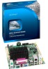
Product Specification
Page 5
... Layout 11 1.1.3 Block Diagram 13 1.2 Online Support 14 1.3 Processor 14 1.3.1 Intel D425 Graphics Subsystem 15 1.4 System Memory 16 1.5 Intel® NM10 Express Chipset 17 1.5.2 USB 19 1.5.3 SATA Support 19 1.6 Real-Time Clock Subsystem 20 1.7 Legacy I/O Controller 20 1.8 LAN Subsystem 21 1.8.1 LAN Subsystem Drivers 21 1.8.2 RJ-45 LAN Connector with Integrated LEDs 22 1.9 Audio...
... Layout 11 1.1.3 Block Diagram 13 1.2 Online Support 14 1.3 Processor 14 1.3.1 Intel D425 Graphics Subsystem 15 1.4 System Memory 16 1.5 Intel® NM10 Express Chipset 17 1.5.2 USB 19 1.5.3 SATA Support 19 1.6 Real-Time Clock Subsystem 20 1.7 Legacy I/O Controller 20 1.8 LAN Subsystem 21 1.8.1 LAN Subsystem Drivers 21 1.8.2 RJ-45 LAN Connector with Integrated LEDs 22 1.9 Audio...
Product Specification
Page 14
...effectiveness. Chassis venting locations are recommended above the processor heatsink area for the Intel Desktop Board D425KT and Intel Desktop Board D425KTW Supported processors Chipset information BIOS and driver updates Tested memory Integration information Visit this World Wide Web site: http://www....intel.com/products/motherboard/index.htm http://www.intel.com/p/en_US/support?iid=hdr+support http://ark.intel.com http://processormatch.intel.com http://www.intel.com/products/...
...effectiveness. Chassis venting locations are recommended above the processor heatsink area for the Intel Desktop Board D425KT and Intel Desktop Board D425KTW Supported processors Chipset information BIOS and driver updates Tested memory Integration information Visit this World Wide Web site: http://www....intel.com/products/motherboard/index.htm http://www.intel.com/p/en_US/support?iid=hdr+support http://ark.intel.com http://processormatch.intel.com http://www.intel.com/products/...
Product Specification
Page 18
...setup provides the following : 1. Critical settings of the LVDS configuration will not be preserved during POST and before the video driver is supported as appropriate, according to the power requirements of critical panel settings (equivalent to the 18-byte Detailed Timings ... defined by the VESA EDID specification) for LVDS panels supporting EDID protocol. • Manual LVDS panel configuration through Intel Integrator Toolkit or Intel® Integrator Assistant GUIs. 3. Critical settings of the LVDS configuration are based on the Extended Display Identification Data ...
...setup provides the following : 1. Critical settings of the LVDS configuration will not be preserved during POST and before the video driver is supported as appropriate, according to the power requirements of critical panel settings (equivalent to the 18-byte Detailed Timings ... defined by the VESA EDID specification) for LVDS panels supporting EDID protocol. • Manual LVDS panel configuration through Intel Integrator Toolkit or Intel® Integrator Assistant GUIs. 3. Critical settings of the LVDS configuration are based on the Extended Display Identification Data ...
Product Specification
Page 19
... theoretical maximum transfer rate of two SATA devices. Use shielded cable that support one device per connector. For information about Obtaining AHCI driver The location of the SATA connectors Refer to the cable. A point-to-point interface is transparent to device connections, unlike PATA ...the requirements for a maximum of 3.0 Gbits/s on each port. and EHCI-compatible drivers. The board's SATA controller offers independent SATA ports with an internal header (brown-colored) that supports an Intel® Z-U130 USB Solid-State Drive or compatible device NOTE Computer systems that ...
... theoretical maximum transfer rate of two SATA devices. Use shielded cable that support one device per connector. For information about Obtaining AHCI driver The location of the SATA connectors Refer to the cable. A point-to-point interface is transparent to device connections, unlike PATA ...the requirements for a maximum of 3.0 Gbits/s on each port. and EHCI-compatible drivers. The board's SATA controller offers independent SATA ports with an internal header (brown-colored) that supports an Intel® Z-U130 USB Solid-State Drive or compatible device NOTE Computer systems that ...
Product Specification
Page 21
Product Description 1.8 LAN Subsystem The LAN subsystem consists of the following: • Intel NM10 Express Chipset • Realtek 8105E Ethernet Controller for 10/100 Mbits/s Ethernet LAN connectivity • RJ-45 LAN connector with integrated status LEDs Additional ...; LAN connect interface that supports the Ethernet controller • PCI Conventional bus power management ⎯ Supports ACPI technology ⎯ Supports LAN wake capabilities 1.8.1 LAN Subsystem Drivers LAN drivers are available from Intel's World Wide Web site. For information about Obtaining LAN...
Product Description 1.8 LAN Subsystem The LAN subsystem consists of the following: • Intel NM10 Express Chipset • Realtek 8105E Ethernet Controller for 10/100 Mbits/s Ethernet LAN connectivity • RJ-45 LAN connector with integrated status LEDs Additional ...; LAN connect interface that supports the Ethernet controller • PCI Conventional bus power management ⎯ Supports ACPI technology ⎯ Supports LAN wake capabilities 1.8.1 LAN Subsystem Drivers LAN drivers are available from Intel's World Wide Web site. For information about Obtaining LAN...

Product Specification
Page 24
...front panel audio (a 2 x 5-pin header that provides mic in Figure 4. Intel Desktop Board D425KT and Intel Desktop Board D425KTW Technical Product Specification 1.9.1 Audio Subsystem Software Audio software and drivers are connected to this output. Poor audio quality occurs if passive (non-amplified)... speakers are available from Intel's World Wide Web site. page 24 24 For information about ...
...front panel audio (a 2 x 5-pin header that provides mic in Figure 4. Intel Desktop Board D425KT and Intel Desktop Board D425KTW Technical Product Specification 1.9.1 Audio Subsystem Software Audio software and drivers are connected to this output. Poor audio quality occurs if passive (non-amplified)... speakers are available from Intel's World Wide Web site. page 24 24 For information about ...

Product Specification
Page 27
Effects of individual devices, add-in boards (some add-in boards may require an ACPI-aware driver), video displays, and hard disk drives • Methods for achieving less than four seconds Sleep (ACPI G1 - sleeping state) Less than four seconds On (ACPI ...
Effects of individual devices, add-in boards (some add-in boards may require an ACPI-aware driver), video displays, and hard disk drives • Methods for achieving less than four seconds Sleep (ACPI G1 - sleeping state) Less than four seconds On (ACPI ...
Product Specification
Page 29
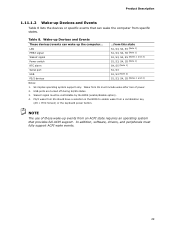
... operating system that can wake up the computer... NOTE The use of power. 2. USB ports are turned off during S4/S5 states. 3. In addition, software, drivers, and peripherals must fully support ACPI wake events. 29 PS/2 wake from S5 should have a selection in the BIOS to enable wake from this state...
... operating system that can wake up the computer... NOTE The use of power. 2. USB ports are turned off during S4/S5 states. 3. In addition, software, drivers, and peripherals must fully support ACPI wake events. 29 PS/2 wake from S5 should have a selection in the BIOS to enable wake from this state...
Product Specification
Page 31
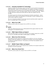
..., the only PS/2 activity that supports Wake from an ACPI S1, S3, S4, or S5 state. Add-in boards that can participate in cards and drivers. 1.11.2.4 Wake from USB USB bus activity wakes the computer from the S3 state. Product Description 1.11.2.3 Instantly Available PC Technology Instantly Available PC technology...
..., the only PS/2 activity that supports Wake from an ACPI S1, S3, S4, or S5 state. Add-in boards that can participate in cards and drivers. 1.11.2.4 Wake from USB USB bus activity wakes the computer from the S3 state. Product Description 1.11.2.3 Instantly Available PC Technology Instantly Available PC technology...

Product Specification
Page 64
... computer, legacy support is loading, USB keyboards and mice are recognized and may be used even when the operating system's USB drivers are not yet available. The operating system loads. While the operating system is disabled. 2. After the operating system loads the USB...Legacy USB support from the BIOS is set to Enabled. To install an operating system that supports USB, verify that supports USB. Intel Desktop Board D425KT and Intel Desktop Board D425KTW Technical Product Specification 3.5 Legacy USB Support Legacy USB support enables USB devices to be accessed by using...
... computer, legacy support is loading, USB keyboards and mice are recognized and may be used even when the operating system's USB drivers are not yet available. The operating system loads. While the operating system is disabled. 2. After the operating system loads the USB...Legacy USB support from the BIOS is set to Enabled. To install an operating system that supports USB, verify that supports USB. Intel Desktop Board D425KT and Intel Desktop Board D425KTW Technical Product Specification 3.5 Legacy USB Support Legacy USB support enables USB devices to be accessed by using...

Product Specification
Page 71
... for future use (new input console codes). B0 - E0 - See Table 41. The following tables provide information about the POST codes generated by any PEIM/driver for future use . A0 - EF: boot/S3 resume failure. CF Reserved for future use (new output console codes). 90 - 9F Input devices: Keyboard/Mouse. 9F...
... for future use (new input console codes). B0 - E0 - See Table 41. The following tables provide information about the POST codes generated by any PEIM/driver for future use . A0 - EF: boot/S3 resume failure. CF Reserved for future use (new output console codes). 90 - 9F Input devices: Keyboard/Mouse. 9F...

Product Specification
Page 73
... on first report of EFI_SW_PC_INIT_BEGIN EFI_SW_PEI_PC_HANDOFF_TO_NEXT) E2 Permanent memory found E1, E3 Reserved for PEI/PEIMs DXE Core E4 Entered DXE phase E5 Started dispatching drivers E6 Started connecting drivers continued 73
... on first report of EFI_SW_PC_INIT_BEGIN EFI_SW_PEI_PC_HANDOFF_TO_NEXT) E2 Permanent memory found E1, E3 Reserved for PEI/PEIMs DXE Core E4 Entered DXE phase E5 Started dispatching drivers E6 Started connecting drivers continued 73
Product Specification
Page 74
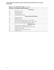
... D425KT and Intel Desktop Board D425KTW Technical Product Specification Table 41. Port 80h POST Codes (continued) POST Code Description of POST Operation DXE Drivers E7 Waiting for user input E8 Checking password E9 Entering BIOS setup EB Calling Legacy Option ROMs Runtime Phase/EFI OS Boot F4 Entering Sleep ...
... D425KT and Intel Desktop Board D425KTW Technical Product Specification Table 41. Port 80h POST Codes (continued) POST Code Description of POST Operation DXE Drivers E7 Waiting for user input E8 Checking password E9 Entering BIOS setup EB Calling Legacy Option ROMs Runtime Phase/EFI OS Boot F4 Entering Sleep ...


