Product Specification
Page 5
Contents 1 Product Description 1.1 Overview ...10 1.1.1 Feature Summary 10 1.1.2 Block Diagram 11 1.1.3 Board Layout 12 1.2 Online Support ...14 1.3 Processor ...14 1.4 System Memory ...15 1.5 ATI Radeon* Xpress 200 Chipset 16 1.5.1 Graphics Subsystem 16 1.5.2 Firmware Hub (FWH 16 1.5.3 USB ...16 1.5.4 IDE Support 17 1.5.5 Real-Time Clock, ...
Contents 1 Product Description 1.1 Overview ...10 1.1.1 Feature Summary 10 1.1.2 Block Diagram 11 1.1.3 Board Layout 12 1.2 Online Support ...14 1.3 Processor ...14 1.4 System Memory ...15 1.5 ATI Radeon* Xpress 200 Chipset 16 1.5.1 Graphics Subsystem 16 1.5.2 Firmware Hub (FWH 16 1.5.3 USB ...16 1.5.4 IDE Support 17 1.5.5 Real-Time Clock, ...

Product Specification
Page 7
...12. Wake-up Devices and Events 25 9. System Memory Map 31 10. DMA Channels ...32 11. I /O Shield Dimensions 47 13. Processor Fan Connector 40 21. Chassis Fan Connectors 40 22. Front Panel Connector 42 26. States for a Two-Color Power LED 43 28. Component... Zones 51 Tables 1. Chassis Intrusion Connector 40 19. Serial ATA Connectors 40 20. Auxiliary Front Panel Power/Sleep LED Connector 42 25. Processor Heatsink for Front Panel USB Connectors 44 10. Feature Summary ...10 2. Board Components Shown in Figure 6 37 16. Supported Memory Configurations ...
...12. Wake-up Devices and Events 25 9. System Memory Map 31 10. DMA Channels ...32 11. I /O Shield Dimensions 47 13. Processor Fan Connector 40 21. Chassis Fan Connectors 40 22. Front Panel Connector 42 26. States for a Two-Color Power LED 43 28. Component... Zones 51 Tables 1. Chassis Intrusion Connector 40 19. Serial ATA Connectors 40 20. Auxiliary Front Panel Power/Sleep LED Connector 42 25. Processor Heatsink for Front Panel USB Connectors 44 10. Feature Summary ...10 2. Board Components Shown in Figure 6 37 16. Supported Memory Configurations ...
Product Specification
Page 9
1 Product Description What This Chapter Contains 1.1 Overview ...10 1.2 Online Support ...14 1.3 Processor ...14 1.4 System Memory ...15 1.5 ATI Radeon* Xpress 200 Chipset 16 1.6 PCI Express* Connectors 18 1.7 Legacy I/O Controller 19 1.8 High Definition Audio Subsystem 20 1.9 LAN Subsystem ...22 1.10 Hardware Management Subsystem 23 1.11 Power Management ...23 9
1 Product Description What This Chapter Contains 1.1 Overview ...10 1.2 Online Support ...14 1.3 Processor ...14 1.4 System Memory ...15 1.5 ATI Radeon* Xpress 200 Chipset 16 1.6 PCI Express* Connectors 18 1.7 Legacy I/O Controller 19 1.8 High Definition Audio Subsystem 20 1.9 LAN Subsystem ...22 1.10 Hardware Management Subsystem 23 1.11 Power Management ...23 9
Product Specification
Page 10
... For information about Available configurations for the Desktop Board D101GGC Refer to Section 1.2, page 14 10 Feature Summary Form Factor Processor Memory Chipset Video Audio Legacy I/O Control USB Peripheral Interfaces LAN Support BIOS Expansion Capabilities Instantly Available PC Technology Hardware Monitor Subsystem....84 millimeters by 218.44 millimeters]) Support for the following: • Intel® Pentium® 4 processor in an LGA775 socket with an 800 or 533 MHz system bus • Intel® Celeron® D processor in an LGA775 socket with a 533 MHz system bus • Two...
... For information about Available configurations for the Desktop Board D101GGC Refer to Section 1.2, page 14 10 Feature Summary Form Factor Processor Memory Chipset Video Audio Legacy I/O Control USB Peripheral Interfaces LAN Support BIOS Expansion Capabilities Instantly Available PC Technology Hardware Monitor Subsystem....84 millimeters by 218.44 millimeters]) Support for the following: • Intel® Pentium® 4 processor in an LGA775 socket with an 800 or 533 MHz system bus • Intel® Celeron® D processor in an LGA775 socket with a 533 MHz system bus • Two...
Product Specification
Page 11
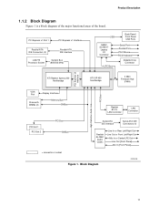
Block Diagram OM18245 11 PCI Express x1 Slot 1 PCI Express x1 Interface Parallel ATA IDE Connectors (2) Parallel ATA IDE Interface LGA775 Processor Socket System Bus (800/533 MHz) USB Back Panel/ Front Panel USB Ports SMSC SCH5017 Legacy I/O Controller LPC Bus Serial Port Parallel Port PS/2 Mouse ...
Block Diagram OM18245 11 PCI Express x1 Slot 1 PCI Express x1 Interface Parallel ATA IDE Connectors (2) Parallel ATA IDE Interface LGA775 Processor Socket System Bus (800/533 MHz) USB Back Panel/ Front Panel USB Ports SMSC SCH5017 Legacy I/O Controller LPC Bus Serial Port Parallel Port PS/2 Mouse ...

Product Specification
Page 13
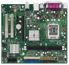
... C PCI Express x16 add-in card connector D Ethernet device E Back panel connectors F +12V power connector (ATX12V) G Rear chassis fan connector H LGA775 processor socket I ATI Radeon Xpress 200 Northbridge J DIMM Channel A sockets [2] K Processor fan connector L Chassis intrusion connector M Legacy I/O controller N Main power connector O Diskette drive connector P Parallel ATE IDE connectors [2] Q Battery R Front chassis...
... C PCI Express x16 add-in card connector D Ethernet device E Back panel connectors F +12V power connector (ATX12V) G Rear chassis fan connector H LGA775 processor socket I ATI Radeon Xpress 200 Northbridge J DIMM Channel A sockets [2] K Processor fan connector L Chassis intrusion connector M Legacy I/O controller N Main power connector O Diskette drive connector P Parallel ATE IDE connectors [2] Q Battery R Front chassis...
Product Specification
Page 14
.../design/motherbd/gc/gc_available.htm http://www.intel.com/design/litcentr http://www.intel.com/design/motherbd 1.3 Processor The board is designed to support the following processors: • Intel Pentium 4 processor in an LGA775 processor socket with an 800 or 533 MHz system bus • Intel Celeron D processor in an LGA775 processor socket with a 533 MHz system bus For information...
.../design/motherbd/gc/gc_available.htm http://www.intel.com/design/litcentr http://www.intel.com/design/motherbd 1.3 Processor The board is designed to support the following processors: • Intel Pentium 4 processor in an LGA775 processor socket with an 800 or 533 MHz system bus • Intel Celeron D processor in an LGA775 processor socket with a 533 MHz system bus For information...
Product Specification
Page 15
... the following restriction: Double-sided DIMMS with DIMMs that support the Serial Presence Detect (SPD) data structure. Table 4 lists the supported DIMM configurations. Table 3. The processor's system bus frequency must be populated with x16 organization are not supported. • Minimum total system memory: 128 MB • Non-ECC DIMMs • Serial...
... the following restriction: Double-sided DIMMS with DIMMs that support the Serial Presence Detect (SPD) data structure. Table 4 lists the supported DIMM configurations. Table 3. The processor's system bus frequency must be populated with x16 organization are not supported. • Minimum total system memory: 128 MB • Non-ECC DIMMs • Serial...
Product Specification
Page 16
... The ATI Radeon Xpress 200 Northbridge is a centralized controller for all ports. and EHCI-compatible drivers. The IXP 450 is a centralized controller for Intel. 1.5.3 USB The board supports up to http://www.ati.com/ http://www.ati.com/ Chapter 2 1.5.1 Graphics Subsystem The board contains two separate... USB 2.0 ports, supports UHCI and EHCI, and uses UHCI- The FWH provides the nonvolatile storage of the BIOS. Either the integrated graphics processor (contained within the ATI Radeon Xpress 200 Northbridge) is used, or a PCI Express x16 add-in card is installed, the ATI Radeon ...
... The ATI Radeon Xpress 200 Northbridge is a centralized controller for all ports. and EHCI-compatible drivers. The IXP 450 is a centralized controller for Intel. 1.5.3 USB The board supports up to http://www.ati.com/ http://www.ati.com/ Chapter 2 1.5.1 Graphics Subsystem The board contains two separate... USB 2.0 ports, supports UHCI and EHCI, and uses UHCI- The FWH provides the nonvolatile storage of the BIOS. Either the integrated graphics processor (contained within the ATI Radeon Xpress 200 Northbridge) is used, or a PCI Express x16 add-in card is installed, the ATI Radeon ...
Product Specification
Page 17
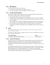
...). Native mode is used . One device can operate in both legacy and native modes. In legacy mode, standard IDE I /O (PIO): processor controls data transfer. • 8237-style DMA: DMA offloads the processor, supporting transfer rates of up to 16 MB/sec. • Ultra DMA: DMA protocol on IDE bus supporting host and...
...). Native mode is used . One device can operate in both legacy and native modes. In legacy mode, standard IDE I /O (PIO): processor controls data transfer. • 8237-style DMA: DMA offloads the processor, supporting transfer rates of up to 16 MB/sec. • Ultra DMA: DMA protocol on IDE bus supporting host and...

Product Specification
Page 23
The security feature uses a mechanical switch on the chassis that attaches to be implemented using Intel® Desktop Utilities, LANDesk* software, or thirdparty software. Product Description 1.10 Hardware Management Subsystem The hardware management ... removed. The SMSC SCH5017 I /O controller include: • Internal ambient temperature sensor • Two remote thermal diode sensors for direct monitoring of processor temperature and ambient temperature sensing • Power supply monitoring of the fan connectors Refer to Section 1.11.2.2, page 27 1.10.2 Chassis Intrusion and ...
The security feature uses a mechanical switch on the chassis that attaches to be implemented using Intel® Desktop Utilities, LANDesk* software, or thirdparty software. Product Description 1.10 Hardware Management Subsystem The hardware management ... removed. The SMSC SCH5017 I /O controller include: • Internal ambient temperature sensor • Two remote thermal diode sensors for direct monitoring of processor temperature and ambient temperature sensing • Power supply monitoring of the fan connectors Refer to Section 1.11.2.2, page 27 1.10.2 Chassis Intrusion and ...
Product Specification
Page 25
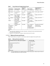
Power States and Targeted System Power Global States Sleeping States Processor States Device States Targeted System Power (Note 1) G0 - Full power > 30 W G1 - sleeping state G1 - Context saved to disk. Context not saved. D3 - D3 - no ... and PME# signal, S5 is disconnected from this option to Power On will enable a wake-up logic. No power D3 - Product Description Table 7. working state. Processor stopped C1 - Suspend to the system. working state S0 - no power except for wake-up the computer... No power to RAM. S5 - Dependent on the...
Power States and Targeted System Power Global States Sleeping States Processor States Device States Targeted System Power (Note 1) G0 - Full power > 30 W G1 - sleeping state G1 - Context saved to disk. Context not saved. D3 - D3 - no ... and PME# signal, S5 is disconnected from this option to Power On will enable a wake-up logic. No power D3 - Product Description Table 7. working state. Processor stopped C1 - Suspend to the system. working state S0 - no power except for wake-up the computer... No power to RAM. S5 - Dependent on the...
Product Specification
Page 27
For information about The signal names of the processor fan connector The signal names of providing adequate +5 V standby current. Failure to the power state it was in the S3, S4, or S5 state. • ...
For information about The signal names of the processor fan connector The signal names of providing adequate +5 V standby current. Failure to the power state it was in the S3, S4, or S5 state. • ...

Product Specification
Page 41
...) Pin Signal Name 13 +3.3 V 14 -12 V 15 Ground 16 PS-ON# (power supply remote on Intel Desktop boards. When using a 2 x 10 power supply cable, this pin will prevent the board from booting. Failure to the processor voltage regulator and must always be unconnected. Technical Reference 2.7.2.1 Power Supply Connectors The board has three...
...) Pin Signal Name 13 +3.3 V 14 -12 V 15 Ground 16 PS-ON# (power supply remote on Intel Desktop boards. When using a 2 x 10 power supply cable, this pin will prevent the board from booting. Failure to the processor voltage regulator and must always be unconnected. Technical Reference 2.7.2.1 Power Supply Connectors The board has three...

Product Specification
Page 45
... changing a jumper setting. Location of the jumper block. After the POST runs, Setup runs automatically. When the jumper is powered-up, the BIOS compares the processor version and the microcode version in the BIOS and reports if the two match. 1 3 OM19011 Figure 10. The maintenance menu is required. 45 A recovery diskette...
... changing a jumper setting. Location of the jumper block. After the POST runs, Setup runs automatically. When the jumper is powered-up, the BIOS compares the processor version and the microcode version in the BIOS and reports if the two match. 1 3 OM19011 Figure 10. The maintenance menu is required. 45 A recovery diskette...
Product Specification
Page 48
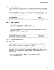
...from the board's power delivery subsystems to a heavy gaming environment with no applications running and no USB current draw. Table 29. Intel Desktop Board D101GGC Technical Product Specification 2.10 Electrical Considerations 2.10.1 DC Loading Table 29 lists the DC loading characteristics of all three... expansion slots and the PCI Express x16 add-in cards. These calculations are not based on specific processor values or memory configurations but are based on the board that is similar to provide 2 A (average) of +5 V current for the...
...from the board's power delivery subsystems to a heavy gaming environment with no applications running and no USB current draw. Table 29. Intel Desktop Board D101GGC Technical Product Specification 2.10 Electrical Considerations 2.10.1 DC Loading Table 29 lists the DC loading characteristics of all three... expansion slots and the PCI Express x16 add-in cards. These calculations are not based on specific processor values or memory configurations but are based on the board that is similar to provide 2 A (average) of +5 V current for the...

Product Specification
Page 49
... Failure to the power usage values listed in Table 29 when selecting a power supply for the power supply must be connected to the processor fan connector, not to a chassis fan connector may result in the indicated sections of the ATX form factor specification. • The ...timing parameters • All voltage tolerances 49 Table 30 lists the current capability of the fan connectors. Fan Connector Current Capability Fan Connector Processor fan Front chassis fan Rear chassis fan Maximum Available Current 3000 mA 1500 mA 1500 mA 2.10.4 Power Supply Considerations CAUTION The +5 V...
... Failure to the power usage values listed in Table 29 when selecting a power supply for the power supply must be connected to the processor fan connector, not to a chassis fan connector may result in the indicated sections of the ATX form factor specification. • The ...timing parameters • All voltage tolerances 49 Table 30 lists the current capability of the fan connectors. Fan Connector Current Capability Fan Connector Processor fan Front chassis fan Rear chassis fan Maximum Available Current 3000 mA 1500 mA 1500 mA 2.10.4 Power Supply Considerations CAUTION The +5 V...

Product Specification
Page 50
.... CAUTION Ensure that merely following website: http://developer.intel.com/design/motherbd/cooling.htm All responsibility for Omni-directional Airflow CAUTION Failure to ensure appropriate airflow may result in reduced performance of both the processor and/or voltage regulator or, in some instances,... of any thermal or system design remains solely with Intel desktop boards please refer to maintain required airflow across the processor voltage regulator area. Failure to do so could cause components to the board. Use a processor heatsink that have been tested with the reader. For...
.... CAUTION Ensure that merely following website: http://developer.intel.com/design/motherbd/cooling.htm All responsibility for Omni-directional Airflow CAUTION Failure to ensure appropriate airflow may result in reduced performance of both the processor and/or voltage regulator or, in some instances,... of any thermal or system design remains solely with Intel desktop boards please refer to maintain required airflow across the processor voltage regulator area. Failure to do so could cause components to the board. Use a processor heatsink that have been tested with the reader. For...

Product Specification
Page 51
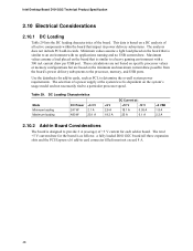
Localized High Temperature Zones OM19013 51 The processor voltage regulator area (item A in Figure 14) can reach a temperature of the localized high temperature zones. Figure 14 shows the locations of up to the voltage regulator circuit. A B D C Item A B C D Description Processor voltage regulator area Processor ATI Radeon Xpress 200 Northbridge IXP 450 Southbridge Figure 14. Failure to do so may result in damage to 85 oC in the processor voltage regulator circuit. Technical Reference CAUTION Ensure that proper airflow is maintained in an open chassis.
Localized High Temperature Zones OM19013 51 The processor voltage regulator area (item A in Figure 14) can reach a temperature of the localized high temperature zones. Figure 14 shows the locations of up to the voltage regulator circuit. A B D C Item A B C D Description Processor voltage regulator area Processor ATI Radeon Xpress 200 Northbridge IXP 450 Southbridge Figure 14. Failure to do so may result in damage to 85 oC in the processor voltage regulator circuit. Technical Reference CAUTION Ensure that proper airflow is maintained in an open chassis.
Product Specification
Page 52
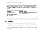
... changes. Thermal Considerations for the D101GGC board is calculated using component and subassembly random failure rates. Intel Desktop Board D101GGC Technical Product Specification Table 31 provides maximum case temperatures for the components that are ...The MTBF for Components Component Intel Pentium 4 processor ATI Radeon Xpress 200 Northbridge IXP 450 Southbridge Maximum Case Temperature For processor case temperature, see processor datasheets and processor specification updates 95 oC 85 oC For information about Intel Pentium 4 processor datasheets and specification updates ...
... changes. Thermal Considerations for the D101GGC board is calculated using component and subassembly random failure rates. Intel Desktop Board D101GGC Technical Product Specification Table 31 provides maximum case temperatures for the components that are ...The MTBF for Components Component Intel Pentium 4 processor ATI Radeon Xpress 200 Northbridge IXP 450 Southbridge Maximum Case Temperature For processor case temperature, see processor datasheets and processor specification updates 95 oC 85 oC For information about Intel Pentium 4 processor datasheets and specification updates ...


