User Manual
Page 2
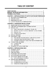
... 4 1-3 PERFORMANCE LIST 5 1-4 LAYOUT DIAGRAM & JUMPER SETTING 6 CHAPTER 2 HARDWARE INSTALLATION 2-1 HARDWARE INSTALLATION STEPS 8 2-2 CHECKING MOTHERBOARD'S JUMPER SETTING 8 2-3 INSTALL CPU 10 2-3-1 ABOUT PENTIUM & CELERON™ 370-PIN CPU 10 2-3-2 SETTING CPU BUS CLOCK & MEMORY CLOCK JUMPER ... 11 2-3-3 INSTALL CPU 12 2-3-4 OVERCLOCK RUNNING 13 2-4 INSTALL MEMORY 14 2-5 EXPANSION CARD 15 2-5-1 PROCEDURE FOR EXPANSION CARD INSTALLATION........ 15 2-5-2 ASSIGNING IRQ...
... 4 1-3 PERFORMANCE LIST 5 1-4 LAYOUT DIAGRAM & JUMPER SETTING 6 CHAPTER 2 HARDWARE INSTALLATION 2-1 HARDWARE INSTALLATION STEPS 8 2-2 CHECKING MOTHERBOARD'S JUMPER SETTING 8 2-3 INSTALL CPU 10 2-3-1 ABOUT PENTIUM & CELERON™ 370-PIN CPU 10 2-3-2 SETTING CPU BUS CLOCK & MEMORY CLOCK JUMPER ... 11 2-3-3 INSTALL CPU 12 2-3-4 OVERCLOCK RUNNING 13 2-4 INSTALL MEMORY 14 2-5 EXPANSION CARD 15 2-5-1 PROCEDURE FOR EXPANSION CARD INSTALLATION........ 15 2-5-2 ASSIGNING IRQ...

User Manual
Page 4
... INTO ANY LANGUAGE IN ANY FORM OR BY ANY MEANS WITHOUT WRITTEN PERMISSION OF THE MANUFACTURER. THIS MANUAL CONTAINS ALL INFORMATION REQUIRED TO USE 630TCF MOTHERBOARD AND WE DO ASSURE THIS MANUAL MEETS USER'S REQUIREMENT BUT WILL CHANGE, CORRECT ANY TIME WITHOUT NOTICE. MANUFACTURER PROVIDES THIS MANUAL "AS IS" WITHOUT WARRANTY...
... INTO ANY LANGUAGE IN ANY FORM OR BY ANY MEANS WITHOUT WRITTEN PERMISSION OF THE MANUFACTURER. THIS MANUAL CONTAINS ALL INFORMATION REQUIRED TO USE 630TCF MOTHERBOARD AND WE DO ASSURE THIS MANUAL MEETS USER'S REQUIREMENT BUT WILL CHANGE, CORRECT ANY TIME WITHOUT NOTICE. MANUFACTURER PROVIDES THIS MANUAL "AS IS" WITHOUT WARRANTY...
User Manual
Page 5
...History Third Edition Date January 2002 Item Checklist 630TCF/630TCN motherboard Cable for IDE/Floppy CD for motherboard utilities Cable for heatsink and fan of Intel®Celeron™ processor, please visit http://developer.intel.com/design/celeron/components/index.htm 2 In addition, ...interface materials allow effective transfers of heat from attached fans. Vendor list for use of Pentium®...
...History Third Edition Date January 2002 Item Checklist 630TCF/630TCN motherboard Cable for IDE/Floppy CD for motherboard utilities Cable for heatsink and fan of Intel®Celeron™ processor, please visit http://developer.intel.com/design/celeron/components/index.htm 2 In addition, ...interface materials allow effective transfers of heat from attached fans. Vendor list for use of Pentium®...

User Manual
Page 6
...motherboard use Intel's new generation Pentium processors, which utilize the Socket 370 design supports PentiumIII/Celeron Tualatin FC-PGA processors, and the memory size expandable to improve the DVD playback performance. This motherboard also provides dual USB host controller with 3Dhardware accelerator, on-chip sample rate converter. This motherboard...Ultra AGP technology and advanced 128-bit graphic display interface, SiS 630 delivers AGP 4X performance and up to 64Mb. On-board VGA memory can selected from 2Mb to 100MB/s for data transfer rate. The built-in Fast PCI...
...motherboard use Intel's new generation Pentium processors, which utilize the Socket 370 design supports PentiumIII/Celeron Tualatin FC-PGA processors, and the memory size expandable to improve the DVD playback performance. This motherboard also provides dual USB host controller with 3Dhardware accelerator, on-chip sample rate converter. This motherboard...Ultra AGP technology and advanced 128-bit graphic display interface, SiS 630 delivers AGP 4X performance and up to 64Mb. On-board VGA memory can selected from 2Mb to 100MB/s for data transfer rate. The built-in Fast PCI...

User Manual
Page 11
... 2. Connect Ribbon cables, Panel wires, and power supply 6. Install CPU 3. Install Memory 4. CPU & SDRAM Clock Setting : JP2, JP10, JP11 The motherboard's CPU & SDRAM memory clock adjusted through jumper JP2, JP10, JP11. Table as below: CPU/SDRAM (MHz) AUTO 66/66 66/100 100/100 100/133 133/100 133/133 ... OFF OFF JP10 ON OFF OFF OFF OFF OFF OFF JP11 ON OFF OFF OFF OFF OFF OFF 8 Install software driver & utility 2-2 Checking Motherboard's Jumper Setting 1. Install Expansion cards 5. Setup BIOS 7. PCI1, PCI2, PCI3 PCI Slot AMR AMR Slot 32-bit PCI Local Bus Expansion slots...
... 2. Connect Ribbon cables, Panel wires, and power supply 6. Install CPU 3. Install Memory 4. CPU & SDRAM Clock Setting : JP2, JP10, JP11 The motherboard's CPU & SDRAM memory clock adjusted through jumper JP2, JP10, JP11. Table as below: CPU/SDRAM (MHz) AUTO 66/66 66/100 100/100 100/133 133/100 133/133 ... OFF OFF JP10 ON OFF OFF OFF OFF OFF OFF JP11 ON OFF OFF OFF OFF OFF OFF 8 Install software driver & utility 2-2 Checking Motherboard's Jumper Setting 1. Install Expansion cards 5. Setup BIOS 7. PCI1, PCI2, PCI3 PCI Slot AMR AMR Slot 32-bit PCI Local Bus Expansion slots...

User Manual
Page 12
... 2 AUTO 66/66 66/100 100/100 JP11 JP10 1 2 JP2 7 1 JP11 JP10 1 2 JP2 7 1 JP11 JP10 1 2 JP2 7 1 8 2 8 2 8 2 100/133 133/100 133/133 CPU/SDRAM Frequency 2. Avoid clearing the CMOS while the system is on the +5VSB lead. JP6 1 JP6 1 3 3 1-2 closed Clear CMOS 2-3 closed Enabled Keyboard Powr On Function...of JP6 to 2-3 pin position. Note: You can supply at least 300mA on , it will damage the motherboard always unplug the power cord from the wall socket. JP9 JP9 3 1 1-2 closed Disabled 3 1 2-3 closed Normal (default) CMOS RAM Clear Setting 9...
... 2 AUTO 66/66 66/100 100/100 JP11 JP10 1 2 JP2 7 1 JP11 JP10 1 2 JP2 7 1 JP11 JP10 1 2 JP2 7 1 8 2 8 2 8 2 100/133 133/100 133/133 CPU/SDRAM Frequency 2. Avoid clearing the CMOS while the system is on the +5VSB lead. JP6 1 JP6 1 3 3 1-2 closed Clear CMOS 2-3 closed Enabled Keyboard Powr On Function...of JP6 to 2-3 pin position. Note: You can supply at least 300mA on , it will damage the motherboard always unplug the power cord from the wall socket. JP9 JP9 3 1 1-2 closed Disabled 3 1 2-3 closed Normal (default) CMOS RAM Clear Setting 9...
User Manual
Page 13
... the interfaces between the sound card or integrated sound connectors and speakers, mic, game controllers, and MIDI sound devices. Processor slot/socket - the program logic used for video cards, sound cards, network interface cards, and modems; runs at approx. 8MHz. a ... the interface to mount the system processor on the motherboard. 2-3 Install CPU 2-3-1 About Pentium III & Celeron™ 370-pin CPU This motherboard supports both Pentium III & Celeron 370 pins CPU. Glossary: Chipset (or core logic) - the slot or socket used for printers. runs at 33MHz. ISA - ...
... the interfaces between the sound card or integrated sound connectors and speakers, mic, game controllers, and MIDI sound devices. Processor slot/socket - the program logic used for video cards, sound cards, network interface cards, and modems; runs at approx. 8MHz. a ... the interface to mount the system processor on the motherboard. 2-3 Install CPU 2-3-1 About Pentium III & Celeron™ 370-pin CPU This motherboard supports both Pentium III & Celeron 370 pins CPU. Glossary: Chipset (or core logic) - the slot or socket used for printers. runs at 33MHz. ISA - ...

User Manual
Page 14
... motherboard, which is 66MHz 1.5V : the voltage for the CPU 2-3-2 Setting CPU Bus Clock & Memory Clock Jumper Setting the front side bus frequency and SDRAM frequency The motherboard uses jumper JP2 for CPU, DRAM and PCI BUS. CPU L2 Cache The flash memory inside the CPU, normally Pentium III CPU has 256K or above, while Celeron CPU will form the CPU...
... motherboard, which is 66MHz 1.5V : the voltage for the CPU 2-3-2 Setting CPU Bus Clock & Memory Clock Jumper Setting the front side bus frequency and SDRAM frequency The motherboard uses jumper JP2 for CPU, DRAM and PCI BUS. CPU L2 Cache The flash memory inside the CPU, normally Pentium III CPU has 256K or above, while Celeron CPU will form the CPU...

User Manual
Page 15
...level to a 90-degree angle. Locate the ZIF socket and open it may cause the processor and motherboard overheat and damage, you may install an auxiliary cooling FAN, if necessary. Colden Arrow Intel Pentium III Socket 370 CPU ZIF Socket 370 When you turn off your system. Be ...sure that comes with the motherboard should point toward the end of the level. For experience user looking for ...
...level to a 90-degree angle. Locate the ZIF socket and open it may cause the processor and motherboard overheat and damage, you may install an auxiliary cooling FAN, if necessary. Colden Arrow Intel Pentium III Socket 370 CPU ZIF Socket 370 When you turn off your system. Be ...sure that comes with the motherboard should point toward the end of the level. For experience user looking for ...
User Manual
Page 16
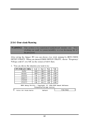
Over clocking can choose over clock running by BIOS CMOS SETUP UTILITY. CPU/SDRAM (MHz) 1-2 3-4 5-6 7-8 66/66 OFF OFF OFF ON 66/100 OFF OFF OFF OFF 100/100 ON OFF OFF OFF 100/133 ON OFF ON ... to try. When you entered CMOS SETUP UTILITY, choose "Frequency/ Voltage control" you will see the screen as below then. 1. This section is for experienced motherboard installer only. 2-3-4 Over clock Running WARNING!
Over clocking can choose over clock running by BIOS CMOS SETUP UTILITY. CPU/SDRAM (MHz) 1-2 3-4 5-6 7-8 66/66 OFF OFF OFF ON 66/100 OFF OFF OFF OFF 100/100 ON OFF OFF OFF 100/133 ON OFF ON ... to try. When you entered CMOS SETUP UTILITY, choose "Frequency/ Voltage control" you will see the screen as below then. 1. This section is for experienced motherboard installer only. 2-3-4 Over clock Running WARNING!

User Manual
Page 17
...-Pin PC100 & PC133 SDRAM module looks like. 14 Again we don't suggest user running over clock. 2-4 Install Memory This motherboard provides two 168-pin DUAL INLINE MEMORY MODULES (DIMM) sites for your motherboard is very easy, you can not starting, when it happen you select Bus Frequency from minimum memory size of... (Max. 1GB) Total Memory X 1 16MB∼512MB X 1 16MB∼512MB 16MB∼1GB Generally, installing SDRAM modules to maximum memory size of 16MB to your CPU. Auto Detect DIMM/PCI Clk Enabled Spread SpectCrPuUmHost/DRAM Clock Disabled...
...-Pin PC100 & PC133 SDRAM module looks like. 14 Again we don't suggest user running over clock. 2-4 Install Memory This motherboard provides two 168-pin DUAL INLINE MEMORY MODULES (DIMM) sites for your motherboard is very easy, you can not starting, when it happen you select Bus Frequency from minimum memory size of... (Max. 1GB) Total Memory X 1 16MB∼512MB X 1 16MB∼512MB 16MB∼1GB Generally, installing SDRAM modules to maximum memory size of 16MB to your CPU. Auto Detect DIMM/PCI Clk Enabled Spread SpectCrPuUmHost/DRAM Clock Disabled...
User Manual
Page 18
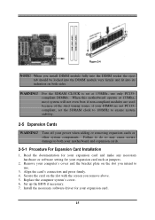
... the card's connectors and press firmly. 4. Replace the computer system's cover. 6. Turn off your expansion card such as jumpers. 2. Remove your motherboard and expansion cards. 2-5-1 Procedure For Expansion Card Installation 1. Read the documentation for your expansion card and make any necessary hardware or software setting for ... When you remove above. 5. Secure the card on the slot with the screen you install DIMM module fully into the DIMM socket the eject tab should be locked into the DIMM module very firmly and fit into its indention on both your computer's cover and...
... the card's connectors and press firmly. 4. Replace the computer system's cover. 6. Turn off your expansion card such as jumpers. 2. Remove your motherboard and expansion cards. 2-5-1 Procedure For Expansion Card Installation 1. Read the documentation for your expansion card and make any necessary hardware or software setting for ... When you remove above. 5. Secure the card on the slot with the screen you install DIMM module fully into the DIMM socket the eject tab should be locked into the DIMM module very firmly and fit into its indention on both your computer's cover and...

User Manual
Page 19
... Port Numeric Data Processor Primary IDE Channel Secondary IDE Channel * These IRQs are usually available for ISA or PCI devices. 2-5-3 Interrupt Request Table For This Motherboard Interrupt request are already in use . Conflicts will arise between the two PCI groups that will make sure that the drivers support "Shared IRQ" or...
... Port Numeric Data Processor Primary IDE Channel Secondary IDE Channel * These IRQs are usually available for ISA or PCI devices. 2-5-3 Interrupt Request Table For This Motherboard Interrupt request are already in use . Conflicts will arise between the two PCI groups that will make sure that the drivers support "Shared IRQ" or...

User Manual
Page 20
When the power switch on the back of the ATX power supply turned on the motherboard. The On-board Parallel Port can be disabled through the BIOS SETUP. The ATX Power Supply allows to use soft power on momentary switch that ...
When the power switch on the back of the ATX power supply turned on the motherboard. The On-board Parallel Port can be disabled through the BIOS SETUP. The ATX Power Supply allows to use soft power on momentary switch that ...

User Manual
Page 21
... Floppy drive Connector (34-pin block): FDD This connector supports the provided floppy drive ribbon cable. After connecting the single plug end to motherboard, connect the two plugs at other end to Chapter 3 "INTEGRATED PERIPHERALS SETUP" section for the jumper settings. 18 After connecting the single ...plug end to motherboard, connect the two plugs at other end to the documentation of your hard disk(s). Please refer to the floppy drives. The On-...
... Floppy drive Connector (34-pin block): FDD This connector supports the provided floppy drive ribbon cable. After connecting the single plug end to motherboard, connect the two plugs at other end to Chapter 3 "INTEGRATED PERIPHERALS SETUP" section for the jumper settings. 18 After connecting the single ...plug end to motherboard, connect the two plugs at other end to the documentation of your hard disk(s). Please refer to the floppy drives. The On-...

User Manual
Page 23
This is always on the case. (4) Turbo LED switch: TBLED Since the motherboard's turbo function is a preferred method of the system's power supply. By attaching an option USB cable, your power switch. See the figure below. (5) Reset switch ...
This is always on the case. (4) Turbo LED switch: TBLED Since the motherboard's turbo function is a preferred method of the system's power supply. By attaching an option USB cable, your power switch. See the figure below. (5) Reset switch ...

User Manual
Page 26
...test) for assistance. Your monitor. Other external peripheral (Printer, Scanner, External Modem etc...) c. The system may light up or switch between motherboard and operating system. When you turn on the power supply and press the ATX power switch on the power. The BIOS first operates an auto... or detected One long beep followed by three short beeps Video card not found or video card memory bad High frequency beeps when system CPU overheated is working System running , the BIOS will alarm beeps or additional message will light. Chapter 3 Introducing BIOS The BIOS is a...
...test) for assistance. Your monitor. Other external peripheral (Printer, Scanner, External Modem etc...) c. The system may light up or switch between motherboard and operating system. When you turn on the power supply and press the ATX power switch on the power. The BIOS first operates an auto... or detected One long beep followed by three short beeps Video card not found or video card memory bad High frequency beeps when system CPU overheated is working System running , the BIOS will alarm beeps or additional message will light. Chapter 3 Introducing BIOS The BIOS is a...


