
English Manual
Page 1
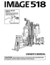
..., . i -. e°.,.4 • : I 7.....".. i..4..•.0..0.e 'ft".... ......s..o. * ..../. .. ..i.r...iI,...I.I ; The serial number can be found in the space above. Write the serial number in the location shown below. IM518021 Serial No. "III 1`% 44 IIIIIIIMW OWNER'S MANUAL CAUTION!: Read all safety precautions and instructions In this manual before using this manual in a safe place for future reference. E Serial Number Decal 11 ,-411114%. e Ms... 1IV Model No. wry • oiiw 'V.0ao•...
..., . i -. e°.,.4 • : I 7.....".. i..4..•.0..0.e 'ft".... ......s..o. * ..../. .. ..i.r...iI,...I.I ; The serial number can be found in the space above. Write the serial number in the location shown below. IM518021 Serial No. "III 1`% 44 IIIIIIIMW OWNER'S MANUAL CAUTION!: Read all safety precautions and instructions In this manual before using this manual in a safe place for future reference. E Serial Number Decal 11 ,-411114%. e Ms... 1IV Model No. wry • oiiw 'V.0ao•...
English Manual
Page 2
... YOU BEGIN ASSEMBLY CABLE DIAGRAMS USING THE IMAGE 518 TROUBLE-SHOOTING AND MAINTENANCE PART LIST WARRANTY/REPLACEMENT PARTS 2 3 .4 25 27 30 31 Back Cover IMPORTANT SAFETY PRECAUTIONS WARNING: To reduce the risk of the holes, the seat may slip during use, causing serious injury. 6. WARNING: Before beginning Ms or any exercise program, consult your hands away4om moving parts other than the designated handles. The weights will fall with pre-existing health prob- Make...
... YOU BEGIN ASSEMBLY CABLE DIAGRAMS USING THE IMAGE 518 TROUBLE-SHOOTING AND MAINTENANCE PART LIST WARRANTY/REPLACEMENT PARTS 2 3 .4 25 27 30 31 Back Cover IMPORTANT SAFETY PRECAUTIONS WARNING: To reduce the risk of the holes, the seat may slip during use, causing serious injury. 6. WARNING: Before beginning Ms or any exercise program, consult your hands away4om moving parts other than the designated handles. The weights will fall with pre-existing health prob- Make...
English Manual
Page 3
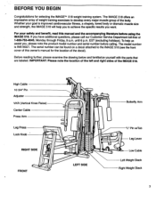
... 3/4" Pin Adjuster VKR (Vertical Knee Raise) Center Cable Press Arm Leg Press Lock Knob RIGHT SIDE FRONT 111•141 7., 1li t" '44 I lilli . V, 814 lull* IN Butterfly Arm Ill LEFT SIDE r 6.0legt "L" Pin w/Tab Leg Lever Low Cable Left Weight Stack Right Weight Stack 3 The IMAGE 518 offers an impressive array of weight training exercises to the IMAGE 518 (see the front cover of this manual and the accompanying literature before calling. The model number...
... 3/4" Pin Adjuster VKR (Vertical Knee Raise) Center Cable Press Arm Leg Press Lock Knob RIGHT SIDE FRONT 111•141 7., 1li t" '44 I lilli . V, 814 lull* IN Butterfly Arm Ill LEFT SIDE r 6.0legt "L" Pin w/Tab Leg Lever Low Cable Left Weight Stack Right Weight Stack 3 The IMAGE 518 offers an impressive array of weight training exercises to the IMAGE 518 (see the front cover of this manual and the accompanying literature before calling. The model number...
English Manual
Page 4
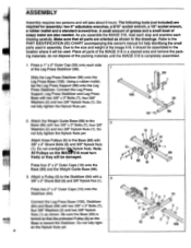
... Included) are also needed. A small amount of grease and a small bowl of the image 518, it should be assembled in the location where it will be damaged. ASSEMBLY Assembly requires two persons and will be used in a cleared area and remove the packing materials; Connect the Leg Press Support, Leg Press Stabilizer and Leg Press Base with two 3/8" x 3" Bolts (7), four 3/8" 2 Washers (2) and two 3/8" Nylock Nuts (1). Attach three Pulleys (9) to the Stabilizer...
... Included) are also needed. A small amount of grease and a small bowl of the image 518, it should be assembled in the location where it will be damaged. ASSEMBLY Assembly requires two persons and will be used in a cleared area and remove the packing materials; Connect the Leg Press Support, Leg Press Stabilizer and Leg Press Base with two 3/8" x 3" Bolts (7), four 3/8" 2 Washers (2) and two 3/8" Nylock Nuts (1). Attach three Pulleys (9) to the Stabilizer...
English Manual
Page 7
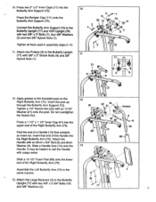
... 13 4 I-* ' . 75 60 13 l . Attach two Pulleys (9) to the Butterfly Upright (77) and VKR Upright (76) with two 3/8" x 2 3/4" Bolts (16) and 3/8" Washers (2). 77 7 Press a 1 1/2" x 1 1/2" Inner Cap (41) into the Right Butterfly Arm (75). Insert that contains an inset nut. Assemble the Left Butterfly Arm (74) in assembly steps 2-10. 11. Press two 2" x 2" Inner Caps (11) into the Butterfly Arm Support (73). e."-73 • 1.,.. 11...
... 13 4 I-* ' . 75 60 13 l . Attach two Pulleys (9) to the Butterfly Upright (77) and VKR Upright (76) with two 3/8" x 2 3/4" Bolts (16) and 3/8" Washers (2). 77 7 Press a 1 1/2" x 1 1/2" Inner Cap (41) into the Right Butterfly Arm (75). Insert that contains an inset nut. Assemble the Left Butterfly Arm (74) in assembly steps 2-10. 11. Press two 2" x 2" Inner Caps (11) into the Butterfly Arm Support (73). e."-73 • 1.,.. 11...
English Manual
Page 9
... two 3/8" x 1 3/4" Bolts (17), two 3/8" Washers (2), an 8mm x 3/4" Bolt (6) and an 8mm Washer (4). Turn the Lock Knob (46) counterclockwise and pull it . 39 59 69 5 14 63 5 58 7 59 68 18. Attach the "U" Handle (68) and the Short Seat Post (69) to the VKR 19 Upright (76) with two 3/8" x 3" Bolts (7), four 3/8" Washers (2)... the Short Seat Post (69). Insert the Short Seat Post (69) into the Leg Lever Frame (70) (see page 27). Press a Tube Cap (39) into each end of a Lock Knob (46) into the Leg Lever Frame (70) and adjust it stops. Make sure that the pin of the Lock Knob is In...
... two 3/8" x 1 3/4" Bolts (17), two 3/8" Washers (2), an 8mm x 3/4" Bolt (6) and an 8mm Washer (4). Turn the Lock Knob (46) counterclockwise and pull it . 39 59 69 5 14 63 5 58 7 59 68 18. Attach the "U" Handle (68) and the Short Seat Post (69) to the VKR 19 Upright (76) with two 3/8" x 3" Bolts (7), four 3/8" Washers (2)... the Short Seat Post (69). Insert the Short Seat Post (69) into the Leg Lever Frame (70) (see page 27). Press a Tube Cap (39) into each end of a Lock Knob (46) into the Leg Lever Frame (70) and adjust it stops. Make sure that the pin of the Lock Knob is In...

English Manual
Page 10
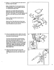
... Grip onto each Handle (13). Tighten the threaded shaft of the Adjuster (103). eL----1 .... 2 .-- ------___,-- _ Remove the wire tie from the outside as shown. Insert those ends of two Handles (13) that contain inset nuts. It may be helpful to 23. Make sure the Bushings remain In place during 1O assembly steps 24 and 25. i:D- 47...
... Grip onto each Handle (13). Tighten the threaded shaft of the Adjuster (103). eL----1 .... 2 .-- ------___,-- _ Remove the wire tie from the outside as shown. Insert those ends of two Handles (13) that contain inset nuts. It may be helpful to 23. Make sure the Bushings remain In place during 1O assembly steps 24 and 25. i:D- 47...
English Manual
Page 11
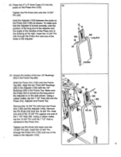
... turned correctly, note the position of the long end of the Adjuster and the angle of the handles of the 7 1/2" Axle (30). Hold the Adjuster (103) between the posts on the Press Arm (102). Using a rubber mallet, tap the 10 3/4" Pin until the 7 1/2" Axle is centered in the Frame Top. Tighten the Pin Knob (44) onto the 103/4" Pin (43). 24. Remove...
... turned correctly, note the position of the long end of the Adjuster and the angle of the handles of the 7 1/2" Axle (30). Hold the Adjuster (103) between the posts on the Press Arm (102). Using a rubber mallet, tap the 10 3/4" Pin until the 7 1/2" Axle is centered in the Frame Top. Tighten the Pin Knob (44) onto the 103/4" Pin (43). 24. Remove...

English Manual
Page 12
...), a Pulley (9) and another 3/4" x 5/16" Spacer onto the Bolt. Tighten a 3/8" Nylock Nut (1) with an 8mm x 3/4" Bolt (6) and an 8mm Washer (4). Tighten the threaded shaft of a Bumper (47) into one 28 side of the Press Arm (102). 26. Insert those ends of the Handles into the sides of the Leg Press Support. Slide a Handle Grip onto each end of the Leg Press Support (99). Attach the Lat Bar...
...), a Pulley (9) and another 3/4" x 5/16" Spacer onto the Bolt. Tighten a 3/8" Nylock Nut (1) with an 8mm x 3/4" Bolt (6) and an 8mm Washer (4). Tighten the threaded shaft of a Bumper (47) into one 28 side of the Press Arm (102). 26. Insert those ends of the Handles into the sides of the Leg Press Support. Slide a Handle Grip onto each end of the Leg Press Support (99). Attach the Lat Bar...
English Manual
Page 13
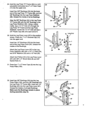
Grease the insides of all six Bushings. Hold the Leg Press Lever (97) in place during assembly step 33. 32 c.-,- 1 , 5 24 98 6-24 104 -, 2 97 Insert four 5/8" Bushings (24) into the lower end of the Leg Press Lever (97). Using a rubber mallet, tap a 13 1/4" Axle (31) through the Leg Press "H" Frame and the Leg Press Stabilizer. Press the 1" x 2" Grooved Cap (12) into the Leg Press Lever (97...
Grease the insides of all six Bushings. Hold the Leg Press Lever (97) in place during assembly step 33. 32 c.-,- 1 , 5 24 98 6-24 104 -, 2 97 Insert four 5/8" Bushings (24) into the lower end of the Leg Press Lever (97). Using a rubber mallet, tap a 13 1/4" Axle (31) through the Leg Press "H" Frame and the Leg Press Stabilizer. Press the 1" x 2" Grooved Cap (12) into the Leg Press Lever (97...
English Manual
Page 14
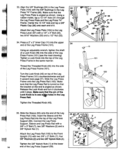
.... Connect the Leg Press Support, Sleeve and Leg Press Rail with a 3/8" x 3" Bolt (7), two 3/8" Washers (2) and a 3/8" Nylock Nut (1). 35 ''2 7 72 2 _4( tel 1 1O0 2 Attach the Leg Press Rail (100) to the Leg Press Lever (97) with a 1/2" x 3" Bolt (34), two 9/16" Washers (33) and a 1/2" Nut (32). 34. Make sure that the pin of the Leg Press Frame (101) counterclockwise and pull it upward (see the inset drawing). Turn the...
.... Connect the Leg Press Support, Sleeve and Leg Press Rail with a 3/8" x 3" Bolt (7), two 3/8" Washers (2) and a 3/8" Nylock Nut (1). 35 ''2 7 72 2 _4( tel 1 1O0 2 Attach the Leg Press Rail (100) to the Leg Press Lever (97) with a 1/2" x 3" Bolt (34), two 9/16" Washers (33) and a 1/2" Nut (32). 34. Make sure that the pin of the Leg Press Frame (101) counterclockwise and pull it upward (see the inset drawing). Turn the...

English Manual
Page 17
Slide the Right and Left Weight Guides Tops (78, 79) onto the upper ends of Cable #1 (91) during assembly steps 45 through 50. Tighten two 8mm x 3/4" Bolts (6) into the Left Weight Guide Top (79). 44. Make ...Upright (72) with two 3/8" x 3" Bolts (7), four 3/8" Washers (2) and two 3/8" Nylock Nuts (1). Carefully observe the drawing at the right to the indicated bracket on the Press Arm (102). 45 _ „----- _ _ 0. ° ., 102 Pin 000 Lay Cable #1 (91) over a Pulley (9). Insert the rubber ring-end of the Weight Guides (56). Attach the Pulley to make sure the Weight Guide...
Slide the Right and Left Weight Guides Tops (78, 79) onto the upper ends of Cable #1 (91) during assembly steps 45 through 50. Tighten two 8mm x 3/4" Bolts (6) into the Left Weight Guide Top (79). 44. Make ...Upright (72) with two 3/8" x 3" Bolts (7), four 3/8" Washers (2) and two 3/8" Nylock Nuts (1). Carefully observe the drawing at the right to the indicated bracket on the Press Arm (102). 45 _ „----- _ _ 0. ° ., 102 Pin 000 Lay Cable #1 (91) over a Pulley (9). Insert the rubber ring-end of the Weight Guides (56). Attach the Pulley to make sure the Weight Guide...

English Manual
Page 18
... sure Cable #1 (914between the Bolt and the Pulley (9). 49 72 9 38 . , •, .0 . . 0 ----1 2 Pin 91 50. Attach a Pulley (9) to the indicated bracket on the Front Upright (72) with a 3/8" x 2" Shank Bolt (8) and 3/8" Nylock Nut (1). ..:: 1 48. Lay Cable #1 (91) over the indicated Pulley (9) on the. Lay Cable #1 (91) over another Pulley (9). Attach a "U" Bracket (52) to the Front Upright (72) in the indicated location. Adjuster (103). Wrap Cable #1 (91).around the.lower Pulley...
... sure Cable #1 (914between the Bolt and the Pulley (9). 49 72 9 38 . , •, .0 . . 0 ----1 2 Pin 91 50. Attach a Pulley (9) to the indicated bracket on the Front Upright (72) with a 3/8" x 2" Shank Bolt (8) and 3/8" Nylock Nut (1). ..:: 1 48. Lay Cable #1 (91) over the indicated Pulley (9) on the. Lay Cable #1 (91) over another Pulley (9). Attach a "U" Bracket (52) to the Front Upright (72) in the indicated location. Adjuster (103). Wrap Cable #1 (91).around the.lower Pulley...

English Manual
Page 20
... the lower Pulley (9) on the Leg Press Support (99). Route the eyelet-end of Cable #2 (92) around the upper Pulley (9) on the indicated "U" Bracket (52). . 52 o 9 9 co 54. Slide the Shank Bolt back in the Front Upright (72). 53. Attach the eyelet-end of Cable #2 (92) to the top of Cable #2 (92) under the Pulley (9) on the Base (89). Route the eyelet-end of Cable #2 (92...
... the lower Pulley (9) on the Leg Press Support (99). Route the eyelet-end of Cable #2 (92) around the upper Pulley (9) on the indicated "U" Bracket (52). . 52 o 9 9 co 54. Slide the Shank Bolt back in the Front Upright (72). 53. Attach the eyelet-end of Cable #2 (92) to the top of Cable #2 (92) under the Pulley (9) on the Base (89). Route the eyelet-end of Cable #2 (92...
English Manual
Page 24
... cables does not move smoothly, locate and correct the problem before using the IMAGE 518, see the cable diagrams on page 27 of numbered Weight Decals (112) to the weight selectors. Before using the IMAGE 518. Next, test the cables and ulleys. Apply one of the sheets of this owner's manual. 69. IMPORTANT: If the cables are tightened securely. 67. The use of the weight stacks as shown. Move the butterfly arms and the leg press...
... cables does not move smoothly, locate and correct the problem before using the IMAGE 518, see the cable diagrams on page 27 of numbered Weight Decals (112) to the weight selectors. Before using the IMAGE 518. Next, test the cables and ulleys. Apply one of the sheets of this owner's manual. 69. IMPORTANT: If the cables are tightened securely. 67. The use of the weight stacks as shown. Move the butterfly arms and the leg press...
English Manual
Page 27
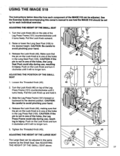
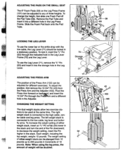
... 27 USING THE IMAGE 518 The instructions below describe how each individual exercise. CAUTION: Be careful to avoid pinching your hand. • 4. CAUTION: If the pin Is not in one of the holes, the Leg Press Frame could slip during use , resulting in the same co manner as the Small Seat. ADJUSTING THE POSITION OF THE SMALL SEAT 1. Tighten the Threaded Knob (45). 46 46 ADJUSTING...
... 27 USING THE IMAGE 518 The instructions below describe how each individual exercise. CAUTION: Be careful to avoid pinching your hand. • 4. CAUTION: If the pin Is not in one of the holes, the Leg Press Frame could slip during use , resulting in the same co manner as the Small Seat. ADJUSTING THE POSITION OF THE SMALL SEAT 1. Tighten the Threaded Knob (45). 46 46 ADJUSTING...
English Manual
Page 28
LOCKING THE LEG LEVER To use the Leg Lever (71), remove the "L" Pin (53) and insert it into a different hole in the Leg Press Frame. CHANGING THE WEIGHT SETTING The dual weight stacks allow two exercise stations to the low cable, leg lever and butterfly arms. To increase the weight setting of weight will be locked in a stationary position. Note: When using the leg press, the amount of either weight stack, insert an...
LOCKING THE LEG LEVER To use the Leg Lever (71), remove the "L" Pin (53) and insert it into a different hole in the Leg Press Frame. CHANGING THE WEIGHT SETTING The dual weight stacks allow two exercise stations to the low cable, leg lever and butterfly arms. To increase the weight setting of weight will be locked in a stationary position. Note: When using the leg press, the amount of either weight stack, insert an...
English Manual
Page 30
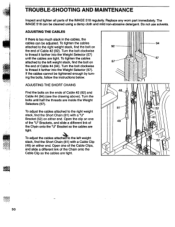
... the drawing above). Do not use solvents. To tighten the cables 94 attached to the left weight stack, find the Short Chain (81) with a Cable Clip 52 (48) on either end. Replace any worn part immediately. TROUBLE-SHOOTING AND=MAINTENANCE Inspect and tighten all parts of the Chain onto the Cable Clip so the cables are tight. 30 Turn the bolt clockwise to thread it farther...
... the drawing above). Do not use solvents. To tighten the cables 94 attached to the left weight stack, find the Short Chain (81) with a Cable Clip 52 (48) on either end. Replace any worn part immediately. TROUBLE-SHOOTING AND=MAINTENANCE Inspect and tighten all parts of the Chain onto the Cable Clip so the cables are tight. 30 Turn the bolt clockwise to thread it farther...
English Manual
Page 31
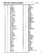
... Butterfly Arm Right Butterfly Arm VKR Upright Butterfly Upright Right Weight Guide Top Left Weight Guide Top Frame Top Short Chain Long Chain "U" Stabilizer Weight Weight Insert Top Weight Weight Selector Screw Weight Guide Base Base Lat Bar Cable #1 Cable #2 Cable #3 Cable #4 Cable #5 Leg Press Stabilizer Leg Press Lever Leg Press "H" Frame Leg Press Support Leg Press Rail Leg Press Frame Press Arm Adjuster Leg Press Plate Long Seat Post Leg Press Base Rower Bar Ankle Strap Hand Strap Ab Strap Bumper Cap Weight Decal Sheet Owner's Manual Exercise Guide Exploded Drawing/Part ID Chart Grease...
... Butterfly Arm Right Butterfly Arm VKR Upright Butterfly Upright Right Weight Guide Top Left Weight Guide Top Frame Top Short Chain Long Chain "U" Stabilizer Weight Weight Insert Top Weight Weight Selector Screw Weight Guide Base Base Lat Bar Cable #1 Cable #2 Cable #3 Cable #4 Cable #5 Leg Press Stabilizer Leg Press Lever Leg Press "H" Frame Leg Press Support Leg Press Rail Leg Press Frame Press Arm Adjuster Leg Press Plate Long Seat Post Leg Press Base Rower Bar Ankle Strap Hand Strap Ab Strap Bumper Cap Weight Decal Sheet Owner's Manual Exercise Guide Exploded Drawing/Part ID Chart Grease...
English Manual
Page 32
... Part No. 113078 6/93 © 1993 Image, Inc. To obtain such free repair or replacement, please tell our Customer Service Department the product's. Also please note that this warranty gives you specific legal rights, you . IF MORE INFORMATION IS REQUIRED, YOU MAY CALL DIRECTLY: 1-800-753-4645 ONE YEAR WARRANTY ON PARTS FIVE YEAR WARRANTY ON WELDS 90 DAY WARRANTY ON UPHOLSTERY During the warranty...
... Part No. 113078 6/93 © 1993 Image, Inc. To obtain such free repair or replacement, please tell our Customer Service Department the product's. Also please note that this warranty gives you specific legal rights, you . IF MORE INFORMATION IS REQUIRED, YOU MAY CALL DIRECTLY: 1-800-753-4645 ONE YEAR WARRANTY ON PARTS FIVE YEAR WARRANTY ON WELDS 90 DAY WARRANTY ON UPHOLSTERY During the warranty...


