Instruction Manual
Page 3
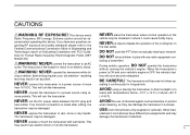
... using or placing the transceiver in direct sunlight or in an electric shock or ruin the transceiver. NEVER cut the DC power cable between the DC plug and fuse holder. The transceiver may be observed when operating this device. taining a transmitter. AVOID ... microphones have any liquids. ving a vehicle. verse polarity. If an incorrect connection is OFF, the vehicle's battery will become exhausted. USE Icom microphones only (supplied or optional). ii NEVER let objects impede the operation of more than 16 V DC. The transceiver will soon become hot...
... using or placing the transceiver in direct sunlight or in an electric shock or ruin the transceiver. NEVER cut the DC power cable between the DC plug and fuse holder. The transceiver may be observed when operating this device. taining a transmitter. AVOID ... microphones have any liquids. ving a vehicle. verse polarity. If an incorrect connection is OFF, the vehicle's battery will become exhausted. USE Icom microphones only (supplied or optional). ii NEVER let objects impede the operation of more than 16 V DC. The transceiver will soon become hot...

Instruction Manual
Page 4
... 12 3 BASIC OPERATION 13-16 Receiving 13 Monitor function 13 Audio mute function 14 Squelch attenuator 14 Transmitting 15 Selecting output power 15 One-touch PTT function 16 SUPPLIED ACCESSORIES q w t y e r q DC power cable (3 m 1 w Mobile mounting bracket 1 e Microphone (HM-133V 1 r Fuse (20 A 1 t Mounting screws, nuts and washers 1 set y Microphone hanger 1 *HM-118N HAND MICROPHONE...
... 12 3 BASIC OPERATION 13-16 Receiving 13 Monitor function 13 Audio mute function 14 Squelch attenuator 14 Transmitting 15 Selecting output power 15 One-touch PTT function 16 SUPPLIED ACCESSORIES q w t y e r q DC power cable (3 m 1 w Mobile mounting bracket 1 e Microphone (HM-133V 1 r Fuse (20 A 1 t Mounting screws, nuts and washers 1 set y Microphone hanger 1 *HM-118N HAND MICROPHONE...
Instruction Manual
Page 7
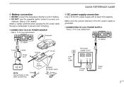
... 13.8 V −⊕ − black ⊕ red Fuses 20 A II Make sure the ground terminal of the DC power supply is grounded. • CONNECTING TO A DC POWER SUPPLY • See p. 72 for the cable connections. Grommet IC-V8000 ⊕ red − black Fuses 20 A _ black + red 12 V 12 V battery NOTE: Crimp Use terminals for fuse...
... 13.8 V −⊕ − black ⊕ red Fuses 20 A II Make sure the ground terminal of the DC power supply is grounded. • CONNECTING TO A DC POWER SUPPLY • See p. 72 for the cable connections. Grommet IC-V8000 ⊕ red − black Fuses 20 A _ black + red 12 V 12 V battery NOTE: Crimp Use terminals for fuse...

Instruction Manual
Page 16
... and transceiver's temperature. (p. 61) r ANTENNA CONNECTOR [ANT] Connects a 50 Ω antenna with the supplied DC power cable. e COOLING FAN Rotates while transmitting. w POWER RECEPTACLE [DC13.8V] Accepts 13.8 V DC ±15% with a PL-259 connector and a 50 Ω coaxial cable. 5 1 PANEL DESCRIPTION Rear panel q e r w q SPEAKER JACK [SP] Accepts an 8 Ω speaker. • Audio output...
... and transceiver's temperature. (p. 61) r ANTENNA CONNECTOR [ANT] Connects a 50 Ω antenna with the supplied DC power cable. e COOLING FAN Rotates while transmitting. w POWER RECEPTACLE [DC13.8V] Accepts 13.8 V DC ±15% with a PL-259 connector and a 50 Ω coaxial cable. 5 1 PANEL DESCRIPTION Rear panel q e r w q SPEAKER JACK [SP] Accepts an 8 Ω speaker. • Audio output...
Instruction Manual
Page 80
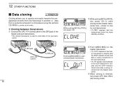
... Cloning allows you to quickly and easily transfer the programmed contents from a personal computer to a transceiver using the optional CS-V8000 CLONING SOFTWARE. power on the master transceiver. • "CL OUT" appears in the sub-transceiver's display and the S/RF indicator shows that .... r When cloning is used to send data to another; w While pushing [M/CALL(PRIO)], turn power ON to exit cloning mode. 69 D Cloning between transceivers q Connect the OPC-474 cloning cable to the [SP] jack of the master and sub-transceivers. • The master transceiver is finished...
... Cloning allows you to quickly and easily transfer the programmed contents from a personal computer to a transceiver using the optional CS-V8000 CLONING SOFTWARE. power on the master transceiver. • "CL OUT" appears in the sub-transceiver's display and the S/RF indicator shows that .... r When cloning is used to send data to another; w While pushing [M/CALL(PRIO)], turn power ON to exit cloning mode. 69 D Cloning between transceivers q Connect the OPC-474 cloning cable to the [SP] jack of the master and sub-transceivers. • The master transceiver is finished...
Instruction Manual
Page 82
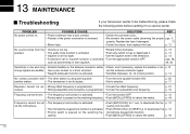
SOLUTION REF. • Check the connector pins. - • Re-connect the power cable observing the proper pgs. p. 72 No sound comes from the • Volume is using tone squelch. p. 14 No contact possible with • The other station ... activated. • Turn the function OFF. • Priority watch is paused on the watching frequency. • Push [M/CALL(PRIO)] to cancel the watch . PROBLEM No power comes on the watching fre- p. 12 p. 44 Frequency cannot be set too tight. • Set the squelch level to the threshold. • A selective call or...
SOLUTION REF. • Check the connector pins. - • Re-connect the power cable observing the proper pgs. p. 72 No sound comes from the • Volume is using tone squelch. p. 14 No contact possible with • The other station ... activated. • Turn the function OFF. • Priority watch is paused on the watching frequency. • Push [M/CALL(PRIO)] to cancel the watch . PROBLEM No power comes on the watching fre- p. 12 p. 44 Frequency cannot be set too tight. • Set the squelch level to the threshold. • A selective call or...

Instruction Manual
Page 85
...-10 EXTERNAL SPEAKER 13 OPC-440/OPC-647 MIC EXTENSION CABLES 14 OPC-441 SPEAKER EXTENSION CABLE OPC-1132/OPC-347 DC POWER CABLES OPC-589 ADAPTER CABLE CS-V8000 CLONING SOFTWARE + OPC-478 CLONING CABLE OPC-474 CLONING CABLE 74 All stated specifications are subject to +60...°C) • Power supply requirement : 13.8 V DC ±15% • Current drain (at 13...
...-10 EXTERNAL SPEAKER 13 OPC-440/OPC-647 MIC EXTENSION CABLES 14 OPC-441 SPEAKER EXTENSION CABLE OPC-1132/OPC-347 DC POWER CABLES OPC-589 ADAPTER CABLE CS-V8000 CLONING SOFTWARE + OPC-478 CLONING CABLE OPC-474 CLONING CABLE 74 All stated specifications are subject to +60...°C) • Power supply requirement : 13.8 V DC ±15% • Current drain (at 13...


