Instruction Manual
Page 3
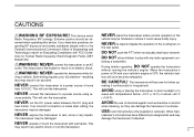
... where normal operation of chemical agents such as benzine or alcohol when cleaning, as they can damage the transceiver's surfaces. BE CAREFUL! USE Icom microphones only (supplied or optional). Extreme caution should be hindered or where it continuously for Human Radio frequency Electromagnetic Fields (OET Bulletin 65) ...ruin the transceiver. NEVER operate the transceiver while dri- This will ruin the transceiver. Other man- ii NEVER cut the DC power cable between the DC plug and fuse holder. verse polarity. The transceiver may be observed when operating this device.
... where normal operation of chemical agents such as benzine or alcohol when cleaning, as they can damage the transceiver's surfaces. BE CAREFUL! USE Icom microphones only (supplied or optional). Extreme caution should be hindered or where it continuously for Human Radio frequency Electromagnetic Fields (OET Bulletin 65) ...ruin the transceiver. NEVER operate the transceiver while dri- This will ruin the transceiver. Other man- ii NEVER cut the DC power cable between the DC plug and fuse holder. verse polarity. The transceiver may be observed when operating this device.

Instruction Manual
Page 4
... Monitor function 13 Audio mute function 14 Squelch attenuator 14 Transmitting 15 Selecting output power 15 One-touch PTT function 16 SUPPLIED ACCESSORIES q w t y e r q DC power cable (3 m 1 w Mobile mounting bracket 1 e Microphone (HM-133V 1 r Fuse (20 A 1 t Mounting screws, nuts and washers 1 set y Microphone hanger 1 *HM-118N HAND MICROPHONE or HM-118TN/TAN DTMF...
... Monitor function 13 Audio mute function 14 Squelch attenuator 14 Transmitting 15 Selecting output power 15 One-touch PTT function 16 SUPPLIED ACCESSORIES q w t y e r q DC power cable (3 m 1 w Mobile mounting bracket 1 e Microphone (HM-133V 1 r Fuse (20 A 1 t Mounting screws, nuts and washers 1 set y Microphone hanger 1 *HM-118N HAND MICROPHONE or HM-118TN/TAN DTMF...
Instruction Manual
Page 7
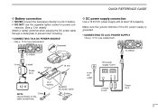
... TO A DC POWER SUPPLY • See p. 72 for the cable connections. IC-V8000 to prevent short circuiting. • CONNECTING TO A DC POWER SOURCE • See p. 72 for details) Attach a rubber grommet when passing the DC power cable through a metal plate to an AC outlet DC power supply 13.8...use the cigarette lighter socket for power connections. (See p. 5 for fuse replacement. Supplied DC power cable Solder D DC power supply connection Use a 13.8 V DC power supply with at least 15 A capacity. Grommet IC-V8000 ⊕ red − black Fuses 20 A _ black + red 12 V 12 V battery ...
... TO A DC POWER SUPPLY • See p. 72 for the cable connections. IC-V8000 to prevent short circuiting. • CONNECTING TO A DC POWER SOURCE • See p. 72 for details) Attach a rubber grommet when passing the DC power cable through a metal plate to an AC outlet DC power supply 13.8...use the cigarette lighter socket for power connections. (See p. 5 for fuse replacement. Supplied DC power cable Solder D DC power supply connection Use a 13.8 V DC power supply with at least 15 A capacity. Grommet IC-V8000 ⊕ red − black Fuses 20 A _ black + red 12 V 12 V battery ...

Instruction Manual
Page 8
... mm (soft solder) 10 mm Soft solder 1-2 mm q Slide the coupling ring down. solder solder e Slide the connector body on the front panel of the IC-V8000. Soft solder the center conductor. A nonradial antenna should be supplied with your local dealer for more information and recommendations. r Screw the coupling ring onto the... mount. QUICK REFERENCE GUIDE D Antenna installation • Antenna location To obtain maximum performance from the transceiver, select a high-quality antenna and mount it . w Strip the cable as shown at left. III Strip the...
... mm (soft solder) 10 mm Soft solder 1-2 mm q Slide the coupling ring down. solder solder e Slide the connector body on the front panel of the IC-V8000. Soft solder the center conductor. A nonradial antenna should be supplied with your local dealer for more information and recommendations. r Screw the coupling ring onto the... mount. QUICK REFERENCE GUIDE D Antenna installation • Antenna location To obtain maximum performance from the transceiver, select a high-quality antenna and mount it . w Strip the cable as shown at left. III Strip the...

Instruction Manual
Page 16
...in set mode and transceiver's temperature. (p. 61) r ANTENNA CONNECTOR [ANT] Connects a 50 Ω antenna with the supplied DC power cable. The plug may cause voltage drops and ignition noise may be superimposed onto transmit or receive audio. Also rotates while receiving depending on the... setting in a vehicle. w POWER RECEPTACLE [DC13.8V] Accepts 13.8 V DC ±15% with a PL-259 connector and a 50 Ω coaxial cable. 5 1 PANEL DESCRIPTION Rear panel q e r w q SPEAKER JACK [SP] Accepts an 8 Ω speaker. • Audio output power is more than 2.0 W. e...
...in set mode and transceiver's temperature. (p. 61) r ANTENNA CONNECTOR [ANT] Connects a 50 Ω antenna with the supplied DC power cable. The plug may cause voltage drops and ignition noise may be superimposed onto transmit or receive audio. Also rotates while receiving depending on the... setting in a vehicle. w POWER RECEPTACLE [DC13.8V] Accepts 13.8 V DC ±15% with a PL-259 connector and a 50 Ω coaxial cable. 5 1 PANEL DESCRIPTION Rear panel q e r w q SPEAKER JACK [SP] Accepts an 8 Ω speaker. • Audio output power is more than 2.0 W. e...
Instruction Manual
Page 80
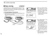
... enter the clone standby condition. r When cloning is used to send data to exit cloning mode. 69 D Cloning between transceivers q Connect the OPC-474 cloning cable to the [SP] jack of the master and sub-transceivers. • The master transceiver is finished, turn power OFF, then ON to the sub-transceiver.... • "CL OUT" appears in the sub-transceiver's display and the S/RF indicator shows that data is being transferred to a transceiver using the optional CS-V8000 CLONING SOFTWARE. e Push [MW(S.MW)] on only While pushing [M/CALL(PRIO)], for sub-transceiver).
... enter the clone standby condition. r When cloning is used to send data to exit cloning mode. 69 D Cloning between transceivers q Connect the OPC-474 cloning cable to the [SP] jack of the master and sub-transceivers. • The master transceiver is finished, turn power OFF, then ON to the sub-transceiver.... • "CL OUT" appears in the sub-transceiver's display and the S/RF indicator shows that data is being transferred to a transceiver using the optional CS-V8000 CLONING SOFTWARE. e Push [MW(S.MW)] on only While pushing [M/CALL(PRIO)], for sub-transceiver).
Instruction Manual
Page 81
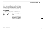
... computer Data can be cloned to the clone standby condition and cloning must be repeated. OTHER FUNCTIONS 12 12 70 D Cloning using the optional CS-V8000 CLONING SOFTWARE and the optional OPC-478 CLONING CABLE. Consult the CS-V8000 CLONING SOFTWARE HELP file for details.
... computer Data can be cloned to the clone standby condition and cloning must be repeated. OTHER FUNCTIONS 12 12 70 D Cloning using the optional CS-V8000 CLONING SOFTWARE and the optional OPC-478 CLONING CABLE. Consult the CS-V8000 CLONING SOFTWARE HELP file for details.
Instruction Manual
Page 82
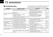
...; Check, and if necessary, replace the feedline or sol- p. p. 12 via the microphone. SOLUTION REF. • Check the connector pins. - • Re-connect the power cable observing the proper pgs. p. 13 p. 14 p. 13 pgs. 48, 49, 50 Sensitivity is too low. • Rotate [VOL] clockwise. has a poor contact or is programmed...
...; Check, and if necessary, replace the feedline or sol- p. p. 12 via the microphone. SOLUTION REF. • Check the connector pins. - • Re-connect the power cable observing the proper pgs. p. 13 p. 14 p. 13 pgs. 48, 49, 50 Sensitivity is too low. • Rotate [VOL] clockwise. has a poor contact or is programmed...

Instruction Manual
Page 85
... REMOTE-CONTROL MICROPHONE SP-10 EXTERNAL SPEAKER 13 OPC-440/OPC-647 MIC EXTENSION CABLES 14 OPC-441 SPEAKER EXTENSION CABLE OPC-1132/OPC-347 DC POWER CABLES OPC-589 ADAPTER CABLE CS-V8000 CLONING SOFTWARE + OPC-478 CLONING CABLE OPC-474 CLONING CABLE 74 not included) : 150(W) × 50(H) × 150(D) mm 529⁄32(W)×...
... REMOTE-CONTROL MICROPHONE SP-10 EXTERNAL SPEAKER 13 OPC-440/OPC-647 MIC EXTENSION CABLES 14 OPC-441 SPEAKER EXTENSION CABLE OPC-1132/OPC-347 DC POWER CABLES OPC-589 ADAPTER CABLE CS-V8000 CLONING SOFTWARE + OPC-478 CLONING CABLE OPC-474 CLONING CABLE 74 not included) : 150(W) × 50(H) × 150(D) mm 529⁄32(W)×...

