Instruction Manual
Page 2
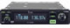
... in most airplanes or vehicles. The dualwatch function allows you to select any of International Business Machines. IBM is easily installed in brightness, not brightness, vividness, high contrast, wide viewing angle and response time compared to an external GPS receiver*...switches between active and standby channels. When connected to a conventional display. The IC-A210 is a registered trademark of memory channels in DC-DC converter accepts a 13.8/27.5 V DC power source. Icom, Icom Inc. and the logo are registered trademarks of personal injury, Þre or...
... in most airplanes or vehicles. The dualwatch function allows you to select any of International Business Machines. IBM is easily installed in brightness, not brightness, vividness, high contrast, wide viewing angle and response time compared to an external GPS receiver*...switches between active and standby channels. When connected to a conventional display. The IC-A210 is a registered trademark of memory channels in DC-DC converter accepts a 13.8/27.5 V DC power source. Icom, Icom Inc. and the logo are registered trademarks of personal injury, Þre or...
Instruction Manual
Page 4
version only 21 5 MENU MODE 22-27 I MENU mode programming 22 I MENU mode items 23 6 INSTALLATION AND REMOVAL 28 I Transceiver installation 28 I Weather memory channel scan (U.S.A. version only 17 I GPS memory 17 I GPS memory edit 18 I Memory protection 18 4 OTHER FUNCTIONS 19-21 I Lock function 19 I ...
version only 21 5 MENU MODE 22-27 I MENU mode programming 22 I MENU mode items 23 6 INSTALLATION AND REMOVAL 28 I Transceiver installation 28 I Weather memory channel scan (U.S.A. version only 17 I GPS memory 17 I GPS memory edit 18 I Memory protection 18 4 OTHER FUNCTIONS 19-21 I Lock function 19 I ...
Instruction Manual
Page 7
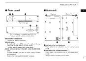
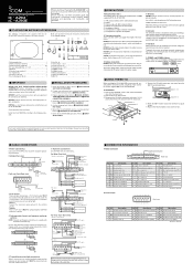
... (For 3rd party products*) Use to attach to p.29 for details. *1Ask your dealer for available GPS receiver details. Refer to an installation rack for 3rd party products* (p. 28). *Ask your dealer for available products details. w DATA JACK q w Connects a 3rd party GPS... receiver*1 or optional cloning cable (OPC-1529R). Refer to an installation rack for Icom products (p. 28). q Metal catch (For Icom products) Use to attach to the "INSTALLATION GUIDE" in details. I Rear panel qw e PANEL DESCRIPTION 1 I Main unit 01 • Top view...
... (For 3rd party products*) Use to attach to p.29 for details. *1Ask your dealer for available GPS receiver details. Refer to an installation rack for 3rd party products* (p. 28). *Ask your dealer for available products details. w DATA JACK q w Connects a 3rd party GPS... receiver*1 or optional cloning cable (OPC-1529R). Refer to an installation rack for Icom products (p. 28). q Metal catch (For Icom products) Use to attach to the "INSTALLATION GUIDE" in details. I Rear panel qw e PANEL DESCRIPTION 1 I Main unit 01 • Top view...
Instruction Manual
Page 32
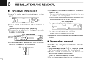
... I Transceiver removal The IC-A210 may easily be removed from the installation rack, if desired. r Visually confirm that the metal catches on the top and bottom of "Transceiver installa- e Pull out the transceiver slowly from ... and removed front panel in the lower socket as shown below when using the installation rack for 3rd party* products. ¥ Main unit front view Use for pre-existing Icom radio installations Use for pre-existing 3rd party radio* installations *Ask your dealer for details. w Turn the wrench counterclockwise until the front panel is...
... I Transceiver removal The IC-A210 may easily be removed from the installation rack, if desired. r Visually confirm that the metal catches on the top and bottom of "Transceiver installa- e Pull out the transceiver slowly from ... and removed front panel in the lower socket as shown below when using the installation rack for 3rd party* products. ¥ Main unit front view Use for pre-existing Icom radio installations Use for pre-existing 3rd party radio* installations *Ask your dealer for details. w Turn the wrench counterclockwise until the front panel is...
Instruction Manual
Page 36
... response 26 Direct frequency selection 5 Direct frequency setting mode operation 8 Displayed message 29 Dualwatch interval 24 Dualwatch operation 8 H Headphone level 23 History memory channel 9, 14 I Installation and removal 28 Intercom function 20 Intercom usable setting 27 Intercom1 Microphone audio input level 23 Intercom1 squelch level 23 Intercom2 Microphone audio input level...
... response 26 Direct frequency selection 5 Direct frequency setting mode operation 8 Displayed message 29 Dualwatch interval 24 Dualwatch operation 8 H Headphone level 23 History memory channel 9, 14 I Installation and removal 28 Intercom function 20 Intercom usable setting 27 Intercom1 Microphone audio input level 23 Intercom1 squelch level 23 Intercom2 Microphone audio input level...

Instruction Manual
Page 37
... channel 10 R Regular memory channel 9, 13 S Safety training information 35 Sidetone level 25 Squelch test function 20 Standby frequency selection 5 T Time-Out-Timer 27 Transceiver installation 28 Transceiver removal 28 Transferring memory contents 12 Transmitting 6 Transmitting microphone selection 25 33
... channel 10 R Regular memory channel 9, 13 S Safety training information 35 Sidetone level 25 Squelch test function 20 Standby frequency selection 5 T Time-Out-Timer 27 Transceiver installation 28 Transceiver removal 28 Transferring memory contents 12 Transmitting 6 Transmitting microphone selection 25 33

Instruction Manual
Page 39
... such hazards. For a small vehicle, the antenna as hospitals, aircraft, and blasting sites. 35 10 SAFETY TRAINING INFORMATION WARNING Your Icom radio generates RF electromagnetic energy during operation. This radio is required to be used only during the course of the vehicle in an uncontrolled... environment. • For compliance with FCC and Industry Canada RF Exposure Requirements, the transmitter antenna installation shall comply with this device and any place on the centre line along the vehicle in areas that can cause FCC RF exposure...
... such hazards. For a small vehicle, the antenna as hospitals, aircraft, and blasting sites. 35 10 SAFETY TRAINING INFORMATION WARNING Your Icom radio generates RF electromagnetic energy during operation. This radio is required to be used only during the course of the vehicle in an uncontrolled... environment. • For compliance with FCC and Industry Canada RF Exposure Requirements, the transmitter antenna installation shall comply with this device and any place on the centre line along the vehicle in areas that can cause FCC RF exposure...
Installation Guide
Page 1
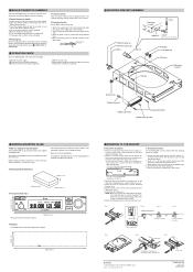
... transceiver with BNC connector (50 Ω). Icom, Icom Inc. Molex is enabled by wiring and installing a yoke-mounted communications/intercom switch. D Yoke-mounted channel and frequency exchange switches NOTE: Channel and frequency selections are required for power and power grounding connections. w Cables. u Preamplifier for the IC-A210/A210E. NEVER bend the cables sharply or...
... transceiver with BNC connector (50 Ω). Icom, Icom Inc. Molex is enabled by wiring and installing a yoke-mounted communications/intercom switch. D Yoke-mounted channel and frequency exchange switches NOTE: Channel and frequency selections are required for power and power grounding connections. w Cables. u Preamplifier for the IC-A210/A210E. NEVER bend the cables sharply or...
Installation Guide
Page 2
...bracket. VSWR is made. Communication capability on both sides for making the mounting hole The IC-A210/A210E can be mounted securely in , pull the lead using moderate force. When installing 2 or more transceivers in the top, bottom, and both the highest and lowest ... 2007 Icom Inc. e Slowly pull the transceiver out from the mounting bracket, if required. , MOLEX CONNECTOR ASSEMBLY The IC-A210/A210E mates with a Molex connector in the connector housing. t Move the lead to the front panel. OPERATION CHECK Check the following points after transceiver installation. - ...
...bracket. VSWR is made. Communication capability on both sides for making the mounting hole The IC-A210/A210E can be mounted securely in , pull the lead using moderate force. When installing 2 or more transceivers in the top, bottom, and both the highest and lowest ... 2007 Icom Inc. e Slowly pull the transceiver out from the mounting bracket, if required. , MOLEX CONNECTOR ASSEMBLY The IC-A210/A210E mates with a Molex connector in the connector housing. t Move the lead to the front panel. OPERATION CHECK Check the following points after transceiver installation. - ...
