

Instruction Manual
Page 3
... jack (CI-V) information 57 14 INTERNAL VIEWS 59 s Top view 59 s Bottom view 59 SUPPLIED ACCESSORIES q w The transceiver comes with the following accessories. q DC power cable 1 w Hand microphone (HM-36 1 e Fuse (FGB 20 A; internal use 1 er 1 Qty. 1 TABLE OF CONTENTS IMPORTANT i EXPLICIT DEFINITIONS i PRECAUTIONS i 1 TABLE OF CONTENTS 1 SUPPLIED ACCESSORIES 1 2 PANEL DESCRIPTION... (option 23 s Filter selection 24 s Filter setting 25 s Function for transmit 26 s Split frequency operation 30 s SWR 30 s Function for CW 31 s Function for DC cable 1 r Fuse (FGB 4 A;
... jack (CI-V) information 57 14 INTERNAL VIEWS 59 s Top view 59 s Bottom view 59 SUPPLIED ACCESSORIES q w The transceiver comes with the following accessories. q DC power cable 1 w Hand microphone (HM-36 1 e Fuse (FGB 20 A; internal use 1 er 1 Qty. 1 TABLE OF CONTENTS IMPORTANT i EXPLICIT DEFINITIONS i PRECAUTIONS i 1 TABLE OF CONTENTS 1 SUPPLIED ACCESSORIES 1 2 PANEL DESCRIPTION... (option 23 s Filter selection 24 s Filter setting 25 s Function for transmit 26 s Split frequency operation 30 s SWR 30 s Function for CW 31 s Function for DC cable 1 r Fuse (FGB 4 A;
Instruction Manual
Page 8
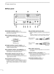
... an optional AT-180 AUTOMATIC ANTENNA TUNER, a TNC for remote operation of a non-Icom linear amplifier. w DC POWER SOCKET [DC 13.8V] (p. 12) Accepts 13.8V DC through the supplied DC power cable. r CI-V REMOTE CONTROL JACK [REMOTE] (p. 57) Designed for use with a ... ALC output jack of transceiver functions. When connecting (⊕) a straight key Rear panel view e TUNER CONTROL SOCKET [TUNER] (p. 14) Accepts the control cable from an optional AH-4 AUTOMATIC ANTENNA TUNER. When connecting a paddle (dot) (com) (dash) i ALC INPUT JACK [ALC] Connects to external equipment...
... an optional AT-180 AUTOMATIC ANTENNA TUNER, a TNC for remote operation of a non-Icom linear amplifier. w DC POWER SOCKET [DC 13.8V] (p. 12) Accepts 13.8V DC through the supplied DC power cable. r CI-V REMOTE CONTROL JACK [REMOTE] (p. 57) Designed for use with a ... ALC output jack of transceiver functions. When connecting (⊕) a straight key Rear panel view e TUNER CONTROL SOCKET [TUNER] (p. 14) Accepts the control cable from an optional AH-4 AUTOMATIC ANTENNA TUNER. When connecting a paddle (dot) (com) (dash) i ALC INPUT JACK [ALC] Connects to external equipment...
Instruction Manual
Page 9
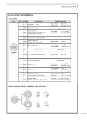
... than 20 mA orange yellow Output voltage : 0 to 8.0 V green Control voltage : -4 to 0 V Input impedance : More than 6.0 V/100 µA green • When connecting the ACC conversion cable (OPC-599) 13 9 10 11 12 5678 1234 2 4 5 1 3 8 6 7 ACC 1 2 4 5 1 3 6 7 ACC 2 ➀ FSKK ➁ GND ➂ SEND ➃ MOD ➄ AF ➅ SQLS ➆ 13.8 V ➇...
... than 20 mA orange yellow Output voltage : 0 to 8.0 V green Control voltage : -4 to 0 V Input impedance : More than 6.0 V/100 µA green • When connecting the ACC conversion cable (OPC-599) 13 9 10 11 12 5678 1234 2 4 5 1 3 8 6 7 ACC 1 2 4 5 1 3 6 7 ACC 2 ➀ FSKK ➁ GND ➂ SEND ➃ MOD ➄ AF ➅ SQLS ➆ 13.8 V ➇...
Instruction Manual
Page 10
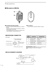
... changes the frequency or memory channel number continuously. • The [UP]/[DN] switch can damage the internal 8 V regulator. • HM-36 SCHEMATIC DIAGRAM MICROPHONE MICROPHONE CABLE MICROPHONE PLUG MIC ELEMENT + 10µ 2k 4700p + 0.33µ 4700p DOWN UP qu wiy ert PTT RECEIVE 470 TRANSMIT 8 w FUNCTION +8 V DC output Frequency up...
... changes the frequency or memory channel number continuously. • The [UP]/[DN] switch can damage the internal 8 V regulator. • HM-36 SCHEMATIC DIAGRAM MICROPHONE MICROPHONE CABLE MICROPHONE PLUG MIC ELEMENT + 10µ 2k 4700p + 0.33µ 4700p DOWN UP qu wiy ert PTT RECEIVE 470 TRANSMIT 8 w FUNCTION +8 V DC output Frequency up...
Instruction Manual
Page 11
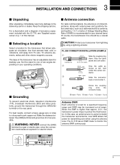
...through the GROUND terminal on your desired band. Low SWR allows full power for a specified frequency range and SWR may be a coaxial cable. The IC-718 has an SWR meter to a long earth-sunk copper rod. Keep the shipping cartons. Set the stand to one of the transceiver... and sensitivity. Select antenna(s), such as a well-matched 50 Ω antenna, and feedline. 1.5:1 or better of critical importance, along with the IC-718, see 'Supplied accessories' on and solder it. When the SWR is useful to protect the final transistor. PL-259 CONNECTOR INSTALLATION EXAMPLE q...
...through the GROUND terminal on your desired band. Low SWR allows full power for a specified frequency range and SWR may be a coaxial cable. The IC-718 has an SWR meter to a long earth-sunk copper rod. Keep the shipping cartons. Set the stand to one of the transceiver... and sensitivity. Select antenna(s), such as a well-matched 50 Ω antenna, and feedline. 1.5:1 or better of critical importance, along with the IC-718, see 'Supplied accessories' on and solder it. When the SWR is useful to protect the final transistor. PL-259 CONNECTOR INSTALLATION EXAMPLE q...
Instruction Manual
Page 14
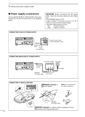
...socket Connect to a 24 V battery. _ black + red NOTE: Use terminals for the cable connections. 3 INSTALLATION AND CONNECTIONS s Power supply connections Use an optional PS-85 DC POWER SUPPLY when operating the IC-718 with AC power. Refer to a battery without supplied DC fuses, otherwise the fire... CAUTION: Before connecting the DC power cable, check the following important items. Make sure: • The [POWER] switch is OFF. • Output voltage of the power source is 12-15 V when you use a non-Icom power supply. • DC power cable polarity is correct. Crimp 12 V ...
...socket Connect to a 24 V battery. _ black + red NOTE: Use terminals for the cable connections. 3 INSTALLATION AND CONNECTIONS s Power supply connections Use an optional PS-85 DC POWER SUPPLY when operating the IC-718 with AC power. Refer to a battery without supplied DC fuses, otherwise the fire... CAUTION: Before connecting the DC power cable, check the following important items. Make sure: • The [POWER] switch is OFF. • Output voltage of the power source is 12-15 V when you use a non-Icom power supply. • DC power cable polarity is correct. Crimp 12 V ...
Instruction Manual
Page 15
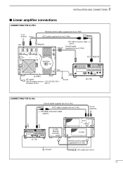
... 13 9 10 11 12 5678 1234 IC-718 CONNECTING THE IC-4KL Coaxial cable (supplied with the IC-4KL) ACC cable (supplied with the IC-4KL) OPC599 conversion cable (option) To an antenna ACC ANT ACC 13 9 10 11 12 5678 1234 IC-718 IC-4KL Remote controller Ground IC-4KL Remote control cable (supplied with the IC-4KL) AC outlet (220-240 V) 13
... 13 9 10 11 12 5678 1234 IC-718 CONNECTING THE IC-4KL Coaxial cable (supplied with the IC-4KL) ACC cable (supplied with the IC-4KL) OPC599 conversion cable (option) To an antenna ACC ANT ACC 13 9 10 11 12 5678 1234 IC-718 IC-4KL Remote controller Ground IC-4KL Remote control cable (supplied with the IC-4KL) AC outlet (220-240 V) 13
Instruction Manual
Page 16
... settings could cause a fire or ruin the linear amplifier. To an antenna RF OUTPUT RF INPUT SEND ALC Non-Icom linear amplifier 50 Ω coaxial cable ANT IC-718 SEND 13 9 10 11 12 5678 1234 ALC The specifications for the SEND relay are 16 V DC 2 A. 3... INSTALLATION AND CONNECTIONS CONNECTING A NON-ICOM LINER AMPLIFIER R WARNING: Set the transceiver output power and linear amplifier ALC output level referring to -4 V, and ...
... settings could cause a fire or ruin the linear amplifier. To an antenna RF OUTPUT RF INPUT SEND ALC Non-Icom linear amplifier 50 Ω coaxial cable ANT IC-718 SEND 13 9 10 11 12 5678 1234 ALC The specifications for the SEND relay are 16 V DC 2 A. 3... INSTALLATION AND CONNECTIONS CONNECTING A NON-ICOM LINER AMPLIFIER R WARNING: Set the transceiver output power and linear amplifier ALC output level referring to -4 V, and ...
Instruction Manual
Page 32
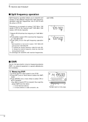
...SET] one or more times to 7.025 MHz/ CW. then read the actual SWR from the meter: ≤ 1.5 well matched antenna ≥ 1.5 check antenna or cable connection, etc. q Select VFO B and set for transmit). e Push [MODE] one or more times to select CW or RTTY operation. • Key down or ...push [PTT] to turn the split frequency operation ON. • Split operation is in VFO B. s SWR The IC-718 has a built-in VFO B (for receive 7.057 MHz/CW and transmit 7.025 MHz/CW. • To change the receive frequency, rotate the main dial, ...
...SET] one or more times to 7.025 MHz/ CW. then read the actual SWR from the meter: ≤ 1.5 well matched antenna ≥ 1.5 check antenna or cable connection, etc. q Select VFO B and set for transmit). e Push [MODE] one or more times to select CW or RTTY operation. • Key down or ...push [PTT] to turn the split frequency operation ON. • Split operation is in VFO B. s SWR The IC-718 has a built-in VFO B (for receive 7.057 MHz/CW and transmit 7.025 MHz/CW. • To change the receive frequency, rotate the main dial, ...

Instruction Manual
Page 50
... Attach the MB-23 CARRYING HANDLE with the supplied rubber feet as shown. 48 s Optional bracket and carrying handle D Mounting bracket An optional IC-MB5 MOBILE MOUNTING BRACKET is danger of the transceiver and 4 screws from the bottom of the transceiver is approx. 3.80kg. 9 INSTALLATION AND ...carry and transport the transceiver. CAUTION: DISCONNECT the DC power cable from the top of electric shock and/or equipment damage. Select an area to mount the receiver keeping in a vehicle, etc. q Remove the 5 screws from the IC-718 before performing any work on a wall, in mind that...
... Attach the MB-23 CARRYING HANDLE with the supplied rubber feet as shown. 48 s Optional bracket and carrying handle D Mounting bracket An optional IC-MB5 MOBILE MOUNTING BRACKET is danger of the transceiver and 4 screws from the bottom of the transceiver is approx. 3.80kg. 9 INSTALLATION AND ...carry and transport the transceiver. CAUTION: DISCONNECT the DC power cable from the top of electric shock and/or equipment damage. Select an area to mount the receiver keeping in a vehicle, etc. q Remove the 5 screws from the IC-718 before performing any work on a wall, in mind that...
Instruction Manual
Page 51
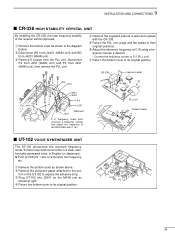
... announce the frequency, etc. q Remove the bottom cover as shown at right. r Return the bottom cover to its original position. y Adjust the reference frequency at cables to their original positions. Frequency check point (Connect a frequency counter and adjust the frequency to 64.00000 MHz with the CR-338. to the bot...
... announce the frequency, etc. q Remove the bottom cover as shown at right. r Return the bottom cover to its original position. y Adjust the reference frequency at cables to their original positions. Frequency check point (Connect a frequency counter and adjust the frequency to 64.00000 MHz with the CR-338. to the bot...
Instruction Manual
Page 52
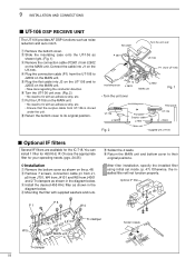
... below . r Mounting the filter with UT-106 s Optional IF filters Several IF filters are available for the IC-718. Connect the cable into J3 on the MAIN unit. After filter installation, specify the installed filter using initial set mode. (p. 47) Otherwise, the installed ...filter will not function properly. w Slide the insulating case onto the UT-106 as shown right. (Fig. 1) e Remove the connection cable (P2601) from J4001 and 2 Tr-clampers as noise reduction and auto notch. 9 INSTALLATION AND CONNECTIONS s UT-106 DSP RECEIVE UNIT The UT-106 ...
... below . r Mounting the filter with UT-106 s Optional IF filters Several IF filters are available for the IC-718. Connect the cable into J3 on the MAIN unit. After filter installation, specify the installed filter using initial set mode. (p. 47) Otherwise, the installed ...filter will not function properly. w Slide the insulating case onto the UT-106 as shown right. (Fig. 1) e Remove the connection cable (P2601) from J4001 and 2 Tr-clampers as noise reduction and auto notch. 9 INSTALLATION AND CONNECTIONS s UT-106 DSP RECEIVE UNIT The UT-106 ...
Instruction Manual
Page 53
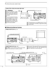
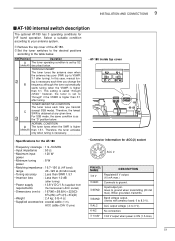
...) : 167(W) × 58.6(H) × 225(D) 69⁄16(W) × 25⁄17(H) × 87⁄8(D) • Weight : 2.4 kg; 5 lb 4 oz • Supplied accessories : coaxial cable (1 m), ACC cable (DIN 13 pins) • Connector information for HF band operation. Therefore, the tuner activates only when tuning is higher than 1.5:1. When grounded, transmits. ➃ BAND...
...) : 167(W) × 58.6(H) × 225(D) 69⁄16(W) × 25⁄17(H) × 87⁄8(D) • Weight : 2.4 kg; 5 lb 4 oz • Supplied accessories : coaxial cable (1 m), ACC cable (DIN 13 pins) • Connector information for HF band operation. Therefore, the tuner activates only when tuning is higher than 1.5:1. When grounded, transmits. ➃ BAND...
Instruction Manual
Page 54
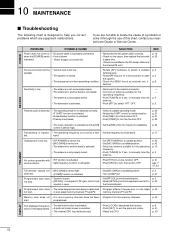
...A quick set too high. p. 6 p. 41 p. 53 SCAN DISPLAY 52 is set mode screen is activated. SOLUTION REF. • Reconnect the DC power cable correctly. • Check for 2 sec. to manually tune the antenna. • Push [ATT] to manually tune the antenna. control is pushed. • ...P2. p. 21 pgs. 7 31, 32 Transmitted signals are installed in the transmitting condition. • Check the SEND line of this chart, contact your nearest Icom Dealer or Service Center. p. 2 p. 27 p. 3 p. 30 Programmed scan does • The same frequencies have not been • Program 2 or ...
...A quick set too high. p. 6 p. 41 p. 53 SCAN DISPLAY 52 is set mode screen is activated. SOLUTION REF. • Reconnect the DC power cable correctly. • Check for 2 sec. to manually tune the antenna. • Push [ATT] to manually tune the antenna. control is pushed. • ...P2. p. 21 pgs. 7 31, 32 Transmitted signals are installed in the transmitting condition. • Check the SEND line of this chart, contact your nearest Icom Dealer or Service Center. p. 2 p. 27 p. 3 p. 30 Programmed scan does • The same frequencies have not been • Program 2 or ...
Instruction Manual
Page 55
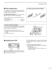
...20 A • Circuitry fuse FGB 4 A DC POWER CABLE FUSE REPLACEMENT 20 A fuse CIRCUITRY FUSE REPLACEMENT The 13.8 V DC from the transceiver when changing a fuse. w While pushing [UP Y] and [Z DN], push [PWR] to their defaults. This fuse is complete. 53 The IC-718 has 2 types of the problem, and replace the damaged... power ON. • The internal CPU is reset. • The transceiver displays its initial VFO frequencies when resetting is installed in the IC-718 through the circuitry fuse. e Replace the top cover. CAUTION: DISCONNECT the DC power cable from the DC power...
...20 A • Circuitry fuse FGB 4 A DC POWER CABLE FUSE REPLACEMENT 20 A fuse CIRCUITRY FUSE REPLACEMENT The 13.8 V DC from the transceiver when changing a fuse. w While pushing [UP Y] and [Z DN], push [PWR] to their defaults. This fuse is complete. 53 The IC-718 has 2 types of the problem, and replace the damaged... power ON. • The internal CPU is reset. • The transceiver displays its initial VFO frequencies when resetting is installed in the IC-718 through the circuitry fuse. e Replace the top cover. CAUTION: DISCONNECT the DC power cable from the DC power...
Instruction Manual
Page 57
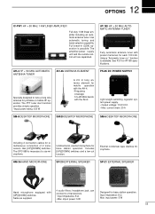
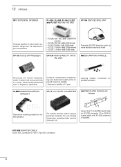
...filters; headphone jack; input power: 5 W 55 current drain: 20 A SM-8 DESKTOP MICROPHONE SM-20 DESKTOP MICROPHONE SM-6 DESKTOP MICROPHONE Including 2 connection cables for AT-180 specifications. Includes [UP]/[DOWN] switches and a low cut function. Electret condenser-type desktop microphone. can connect to use microphone... HF + 50 MHz AUTOMATIC ANTENNA TUNER Specially designed to tune a long wire antenna for each 100 kHz. 12 OPTIONS IC-PW1 HF + 50 MHz 1 KW LINER AMPLIFIER Full-duty 1 kW linear amplifier including an automatic antenna tuner. Input impedance: 8 Ω ...
...filters; headphone jack; input power: 5 W 55 current drain: 20 A SM-8 DESKTOP MICROPHONE SM-20 DESKTOP MICROPHONE SM-6 DESKTOP MICROPHONE Including 2 connection cables for AT-180 specifications. Includes [UP]/[DOWN] switches and a low cut function. Electret condenser-type desktop microphone. can connect to use microphone... HF + 50 MHz AUTOMATIC ANTENNA TUNER Specially designed to tune a long wire antenna for each 100 kHz. 12 OPTIONS IC-PW1 HF + 50 MHz 1 KW LINER AMPLIFIER Full-duty 1 kW linear amplifier including an automatic antenna tuner. Input impedance: 8 Ω ...
Instruction Manual
Page 58
IC-MB5 MOBILE MOUNTING BRACKET CT-17 CI-V LEVEL CONVERTER AH-710 FOLDED DIPOLE ANTENNA ... wide) Provides AF DSP functions such as noise reduction and auto notch. Covers from 1.9-30 MHz bands. OPC-599 ADAPTER CABLE 13-pin, ACC connector to 7-pin + 8-pin ACC connector. 56 Height can change frequencies, operating mode, memory channels,... etc. Has an SO-239 connector. 30 m (98.4 ft) coaxial cable with PL-259 connector is supplied. For remote receiver control using a personal computer. UT-102 VOICE SYNTHESIZER CR-338 HIGH-...
IC-MB5 MOBILE MOUNTING BRACKET CT-17 CI-V LEVEL CONVERTER AH-710 FOLDED DIPOLE ANTENNA ... wide) Provides AF DSP functions such as noise reduction and auto notch. Covers from 1.9-30 MHz bands. OPC-599 ADAPTER CABLE 13-pin, ACC connector to 7-pin + 8-pin ACC connector. 56 Height can change frequencies, operating mode, memory channels,... etc. Has an SO-239 connector. 30 m (98.4 ft) coaxial cable with PL-259 connector is supplied. For remote receiver control using a personal computer. UT-102 VOICE SYNTHESIZER CR-338 HIGH-...
Instruction Manual
Page 59
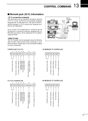
Up to 4 Icom CI-V transceivers or receivers can be connected through an optional CT-17 CI-V LEVEL CONVERTER to a personal computer equipped with an RS-232C port. IC-718 ˛ ˛ BC-25 (optional) 9-15 V DC ct- 17 personal computer mini-plug cable CONTROLLER TO IC-718 q wert y u FE FE 5E E0 Cn ... End of message code (fixed) Preamble code (fixed) Controller's default address Transceiver's default address OK code (fixed) End of message code (fixed) IC-718 TO CONTROLLER q wert y u FE FE E0 5E Cn Sc Data area FD NG MESSAGE TO CONTROLLER FE FE E0 5E FA FD Preamble code ...
Up to 4 Icom CI-V transceivers or receivers can be connected through an optional CT-17 CI-V LEVEL CONVERTER to a personal computer equipped with an RS-232C port. IC-718 ˛ ˛ BC-25 (optional) 9-15 V DC ct- 17 personal computer mini-plug cable CONTROLLER TO IC-718 q wert y u FE FE 5E E0 Cn ... End of message code (fixed) Preamble code (fixed) Controller's default address Transceiver's default address OK code (fixed) End of message code (fixed) IC-718 TO CONTROLLER q wert y u FE FE E0 5E Cn Sc Data area FD NG MESSAGE TO CONTROLLER FE FE E0 5E FA FD Preamble code ...


