
Operation Guide
Page 9
... installed and used in the United Kingdom. This device complies with the limits for a Class A digital device, pursuant to Part 15 of the FCC Rules. Operator's Guide v These limits are designed to provide reasonable protection against harmful interference when the equipment is ...operated in which case the user will be used in accordance with the instruction manual, may cause undesired operation. IBM is likely to cause harmful interference, in a commercial environment. The United Kingdom Telecommunications Statement of Compliance: This apparatus is subject...
... installed and used in the United Kingdom. This device complies with the limits for a Class A digital device, pursuant to Part 15 of the FCC Rules. Operator's Guide v These limits are designed to provide reasonable protection against harmful interference when the equipment is ...operated in which case the user will be used in accordance with the instruction manual, may cause undesired operation. IBM is likely to cause harmful interference, in a commercial environment. The United Kingdom Telecommunications Statement of Compliance: This apparatus is subject...

Operation Guide
Page 29
... printer interface. Twinax Interface*: Effective in NOT READY state. Serial/Parallel Interface: It is displayed. Effective in READY and NOT READY state. Cancel Operator's Guide 15 Coax Interface (SCS mode)*: Effective in NOT READY state but the action will occur in progress. 2) Cancels a print job. When pressed, "059 CANCEL PRINT ACTIVE...
... printer interface. Twinax Interface*: Effective in NOT READY state. Serial/Parallel Interface: It is displayed. Effective in READY and NOT READY state. Cancel Operator's Guide 15 Coax Interface (SCS mode)*: Effective in NOT READY state but the action will occur in progress. 2) Cancels a print job. When pressed, "059 CANCEL PRINT ACTIVE...

Operation Guide
Page 43
... should not normally need to count columns. You can also use the paper scale to adjust the position of the left tractor. Tractor Door Paper 15 Load the paper on the paper scale and lock it.
... should not normally need to count columns. You can also use the paper scale to adjust the position of the left tractor. Tractor Door Paper 15 Load the paper on the paper scale and lock it.
Operation Guide
Page 50
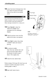
... Cancel to clear the "END OF FORMS" fault message from the message display. 14 Close the printer cover and the cabinet front door, as required. 15 Press Start to match the paper thickness. excessive friction can cause paper jams and ribbon jams with potential for ribbon damage, smeared ink, or wavy...
... Cancel to clear the "END OF FORMS" fault message from the message display. 14 Close the printer cover and the cabinet front door, as required. 15 Press Start to match the paper thickness. excessive friction can cause paper jams and ribbon jams with potential for ribbon damage, smeared ink, or wavy...
Operation Guide
Page 96
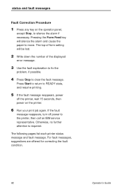
...fault messages, suggestions are offered for correcting the fault condition. 82 Operator's Guide If the fault message reappears, turn off the printer, wait 15 seconds, then power on the operator panel, except Stop, to clear the fault message. Otherwise, no further attention is required. The following ...6 Run your print job again. The top-of-form setting will silence the alarm and cause the paper to the printer, then call an IBM service representative. Press Start to return to READY state, and resume printing. 5 If the fault message reappears, power off power to move. Pressing...
...fault messages, suggestions are offered for correcting the fault condition. 82 Operator's Guide If the fault message reappears, turn off the printer, wait 15 seconds, then power on the operator panel, except Stop, to clear the fault message. Otherwise, no further attention is required. The following ...6 Run your print job again. The top-of-form setting will silence the alarm and cause the paper to the printer, then call an IBM service representative. Press Start to return to READY state, and resume printing. 5 If the fault message reappears, power off power to move. Pressing...

Maintenance Manual
Page 5
Table of Contents 1 Maintenance Overview About the Printer 13 The IBM 6400 Series Printer Family 13 Printer Evolution 15 How to Identify the Printer 15 Important Maintenance Notes 16 About This Manual 16 How to Use This Manual 16 Notes and Notices 16 Printing Conventions in This Manual 18 Related ...
Table of Contents 1 Maintenance Overview About the Printer 13 The IBM 6400 Series Printer Family 13 Printer Evolution 15 How to Identify the Printer 15 Important Maintenance Notes 16 About This Manual 16 How to Use This Manual 16 Notes and Notices 16 Printing Conventions in This Manual 18 Related ...

Maintenance Manual
Page 15
..., which are not compatible with earlier models. Interpreting the Printer Model Number Maintenance Overview 15 How to Identify the Printer The model number of the printer indicates printer family, speed, and type of enclosure. (See Figure 1.) IBM 6400 Printer Family 6400-04P Speed Rating: 004 = 475 lpm 005 = 500 lpm (25 MHz controller) 050...
..., which are not compatible with earlier models. Interpreting the Printer Model Number Maintenance Overview 15 How to Identify the Printer The model number of the printer indicates printer family, speed, and type of enclosure. (See Figure 1.) IBM 6400 Printer Family 6400-04P Speed Rating: 004 = 475 lpm 005 = 500 lpm (25 MHz controller) 050...

Maintenance Manual
Page 43
... Ribbon Guide Left Ribbon Motor Print Mechanism Flex Circuits: Shuttle Assy Terminator Board Shuttle Motor Hammer Bank Board Shuttle Assembly MPU Hammer Bank Fan Figure 15. Logical Control of Operation Cabinet Exhaust Fan (Cabinet models only) Paper Feed Motor Platen Open Switch Right Ribbon Guide Right Ribbon Motor 43 See Figure...
... Ribbon Guide Left Ribbon Motor Print Mechanism Flex Circuits: Shuttle Assy Terminator Board Shuttle Motor Hammer Bank Board Shuttle Assembly MPU Hammer Bank Fan Figure 15. Logical Control of Operation Cabinet Exhaust Fan (Cabinet models only) Paper Feed Motor Platen Open Switch Right Ribbon Guide Right Ribbon Motor 43 See Figure...

Maintenance Manual
Page 52
... that will remain stable for logic. There is an opto-isolated input on the controller board and may be pulled down to a level lower than 15 V in a single-point ground. The + 5 V output will shut down and latch off the + 48 V and + 8.5 V supplies unless it is a + 5 V bus for reporting and latching the...
... that will remain stable for logic. There is an opto-isolated input on the controller board and may be pulled down to a level lower than 15 V in a single-point ground. The + 5 V output will shut down and latch off the + 48 V and + 8.5 V supplies unless it is a + 5 V bus for reporting and latching the...

Maintenance Manual
Page 58
... first thing to print again but will display another error message until the conditions are corrected. Unrecoverable conditions require that may be powered off , wait 15 seconds, then power the printer back on . If the message reappears, classify the check condition unrecoverable. Clearing Error Messages Refer to the Message List below...
... first thing to print again but will display another error message until the conditions are corrected. Unrecoverable conditions require that may be powered off , wait 15 seconds, then power the printer back on . If the message reappears, classify the check condition unrecoverable. Clearing Error Messages Refer to the Message List below...

Maintenance Manual
Page 131
.../PAPR M is damaged or fails continuity test. Press Form Feed and View several times and check that the forms thickness lever is not being used . 15.2 ± 1.5 Ohms on both phases. (Refer to the power stacker control panel PCBA pinout drawing on page 304.) Replace any motor that fails the resistance...
.../PAPR M is damaged or fails continuity test. Press Form Feed and View several times and check that the forms thickness lever is not being used . 15.2 ± 1.5 Ohms on both phases. (Refer to the power stacker control panel PCBA pinout drawing on page 304.) Replace any motor that fails the resistance...

Maintenance Manual
Page 140
Make sure that recalibrates hammer coil temperature. Press: Enter PRINTER MECHANISM TESTS Burn In Test Press Enter to be in NOT READY state to 6400-014 and 6400-15 printers. ENABLE permits the line to view the different mechanism tests. 140 Troubleshooting Print Partial Line: If the final line of page perforations when top... in the buffer. Set Coil Temperature: An automatic sequence in printer software that the printer ribbon is loaded with paper. 2. DISABLE holds the line in 6400-004, -04P, -005, and -05P printers.
Make sure that recalibrates hammer coil temperature. Press: Enter PRINTER MECHANISM TESTS Burn In Test Press Enter to be in NOT READY state to 6400-014 and 6400-15 printers. ENABLE permits the line to view the different mechanism tests. 140 Troubleshooting Print Partial Line: If the final line of page perforations when top... in the buffer. Set Coil Temperature: An automatic sequence in printer software that the printer ribbon is loaded with paper. 2. DISABLE holds the line in 6400-004, -04P, -005, and -05P printers.

Maintenance Manual
Page 142
... powering up the printer. While holding down the Eject/Restore and Stop keys. 3. Press the ENTER key. Power on ). 4. Activating the Boot Diagnostic Menu 1. Wait 15 seconds. 3. To exit the hidden diagnostic menu, you can access by holding the Eject/Restore and Stop keys, set the printer power switch to 1 (on...
... powering up the printer. While holding down the Eject/Restore and Stop keys. 3. Press the ENTER key. Power on ). 4. Activating the Boot Diagnostic Menu 1. Wait 15 seconds. 3. To exit the hidden diagnostic menu, you can access by holding the Eject/Restore and Stop keys, set the printer power switch to 1 (on...

Maintenance Manual
Page 147
... 8 8 11 9 HT 9 9 10 1 0 10 1 1 11 0 0 11 0 1 11 1 0 11 1 1 12 10 LF 10 0 A 13 11 VT 11 0 B 14 12 FF 12 0 C 15 13 CR 13 0 D 16 14 SO 14 0 E 17 15 SI 15 0 F 0 0 1 1 20 DLE 16 10 DC1 (XON) 21 17 11 22 DC2 18 12 DC3 (XOFF) 23 19 13 24 DC4 20... 14 25 NAK 21 15 26 SYN 22 16 27 ETB 23 17 30 CAN 24 18 31 EM 25 19 32 SUB 26 1A 33 ESC 27 1B 34 ...
... 8 8 11 9 HT 9 9 10 1 0 10 1 1 11 0 0 11 0 1 11 1 0 11 1 1 12 10 LF 10 0 A 13 11 VT 11 0 B 14 12 FF 12 0 C 15 13 CR 13 0 D 16 14 SO 14 0 E 17 15 SI 15 0 F 0 0 1 1 20 DLE 16 10 DC1 (XON) 21 17 11 22 DC2 18 12 DC3 (XOFF) 23 19 13 24 DC4 20... 14 25 NAK 21 15 26 SYN 22 16 27 ETB 23 17 30 CAN 24 18 31 EM 25 19 32 SUB 26 1A 33 ESC 27 1B 34 ...

Maintenance Manual
Page 150
Soft vs. This is simply refreshed with the power-up printer configuration. Wait 15 seconds. 3. Set the printer power switch to do a soft reset: 1. The LCD displays "STANDBY...", "SOFT RESET" while the printer loads the power-up configuration into ...
Soft vs. This is simply refreshed with the power-up printer configuration. Wait 15 seconds. 3. Set the printer power switch to do a soft reset: 1. The LCD displays "STANDBY...", "SOFT RESET" while the printer loads the power-up configuration into ...

Maintenance Manual
Page 160
... screws. (See page 271, Figure 44, items 3, 4, and 5.) 10. Loosen (do not remove) the motor mount bolts (2). 6. Using the straight end of a force gauge, apply 15 pounds (66.7 N) of the motor. Reduce tension to 12 pounds (53.4 N) and torque the paper feed motor mount bolts (2) to the paper feed drive motor...
... screws. (See page 271, Figure 44, items 3, 4, and 5.) 10. Loosen (do not remove) the motor mount bolts (2). 6. Using the straight end of a force gauge, apply 15 pounds (66.7 N) of the motor. Reduce tension to 12 pounds (53.4 N) and torque the paper feed motor mount bolts (2) to the paper feed drive motor...

Maintenance Manual
Page 178
... Scroll" + Scroll# to put the printer into READY mode. 178 Adjustment Procedures Press Scroll" or Scroll# until the comb pattern prints at the same time.) 15. Press Enter. If the comb pattern printed beyond the perforation, decrease the number of the display. 18. The top line of dots. 17. Reload the...
... Scroll" + Scroll# to put the printer into READY mode. 178 Adjustment Procedures Press Scroll" or Scroll# until the comb pattern prints at the same time.) 15. Press Enter. If the comb pattern printed beyond the perforation, decrease the number of the display. 18. The top line of dots. 17. Reload the...

Maintenance Manual
Page 180
... / PRINTER MECHANISM TESTS". 11. The display shows "NOT READY". 16. Press Scroll" + Scroll" to activate the value as shown below: Needs Adjustment Correct Needs Adjustment 15. 9. Press Enter. The phasing index (followed by the phasing index number. 10. Press Scroll" or Scroll" to increase or decrease the phasing index, then press...
... / PRINTER MECHANISM TESTS". 11. The display shows "NOT READY". 16. Press Scroll" + Scroll" to activate the value as shown below: Needs Adjustment Correct Needs Adjustment 15. 9. Press Enter. The phasing index (followed by the phasing index number. 10. Press Scroll" or Scroll" to increase or decrease the phasing index, then press...

Maintenance Manual
Page 183
... Scroll" key; When the file has successfully loaded into the printer serial port, enter the following DOS commands: MODE COM1:9600,N,8,1,P FILENAME.EXE -PBC1 20. 15. When the printer download port you of the load process and status. (See Table 5.) 21.
... Scroll" key; When the file has successfully loaded into the printer serial port, enter the following DOS commands: MODE COM1:9600,N,8,1,P FILENAME.EXE -PBC1 20. 15. When the printer download port you of the load process and status. (See Table 5.) 21.

Maintenance Manual
Page 189
...key. Select and run the Ripple Print printer test (page 135). 14. If the Ready indicator is currently active. 7. Press Stop to models 6400-004, -04P, -005, and -05P. Adjustment Procedures 189 Do this procedure if the original CMX board or shuttle frame assembly were removed ...and reinstalled as part of other option. 15. Power on the display. 4. Press Scroll" + Scroll# + Return + Enter. (Press all four keys at the same time.) "SERVICE / PRINTER MECHANISM ...
...key. Select and run the Ripple Print printer test (page 135). 14. If the Ready indicator is currently active. 7. Press Stop to models 6400-004, -04P, -005, and -05P. Adjustment Procedures 189 Do this procedure if the original CMX board or shuttle frame assembly were removed ...and reinstalled as part of other option. 15. Power on the display. 4. Press Scroll" + Scroll# + Return + Enter. (Press all four keys at the same time.) "SERVICE / PRINTER MECHANISM ...