

Parts Catalog
Page 15
..., Gauge Nut Centerlock 3/8-16 unc Washer 13/32 x 1-1/2 x 11 Ga. inches 1 inch = 25.4 mm 15 pulley/nut/washer and blade bolt/washers not included) Replacement Mower, Complete NOTE: All component dimensions given in U.S. TRACTOR - NO. 1 532 44 24-05 2 532 40 55-07 3 532 40 55-06 6 532 19 51-86... housing, shaft assembly, and bearing only - MODEL NO. Pulley Idler Spring Return Stud Fastener Nut Lock Hex Flange Washer 13/32 x 13/16 x 12 Ga. YT46LS (96043015100), PRODUCT NO. 960 43 01-51 MOWER DECK KEY PART NO.
..., Gauge Nut Centerlock 3/8-16 unc Washer 13/32 x 1-1/2 x 11 Ga. inches 1 inch = 25.4 mm 15 pulley/nut/washer and blade bolt/washers not included) Replacement Mower, Complete NOTE: All component dimensions given in U.S. TRACTOR - NO. 1 532 44 24-05 2 532 40 55-07 3 532 40 55-06 6 532 19 51-86... housing, shaft assembly, and bearing only - MODEL NO. Pulley Idler Spring Return Stud Fastener Nut Lock Hex Flange Washer 13/32 x 13/16 x 12 Ga. YT46LS (96043015100), PRODUCT NO. 960 43 01-51 MOWER DECK KEY PART NO.
Parts Catalog
Page 16
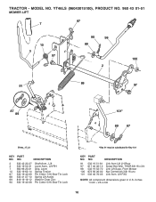
... Zinc 90 532 19 42-08 Pin Cotter 5/16 Bow Tie Lock *Key 91 may be substituted for Key 101 KEY PART NO. NO. Front Mower 100 873 93 06-00 Nut Centerlock 3/8-16 unc 101 532 40 70-03 Link Asm. inches 1 inch = 25.4 mm 16... YT46LS (96043015100), PRODUCT NO. 960 43 01-51 MOWER LIFT 87 7 10 3 97 90 98 89 100 2 91 88 97 87 89 101* 89 87 lift-tex_17_r3 KEY PART NO. DESCRIPTION 91...
... Zinc 90 532 19 42-08 Pin Cotter 5/16 Bow Tie Lock *Key 91 may be substituted for Key 101 KEY PART NO. NO. Front Mower 100 873 93 06-00 Nut Centerlock 3/8-16 unc 101 532 40 70-03 Link Asm. inches 1 inch = 25.4 mm 16... YT46LS (96043015100), PRODUCT NO. 960 43 01-51 MOWER LIFT 87 7 10 3 97 90 98 89 100 2 91 88 97 87 89 101* 89 87 lift-tex_17_r3 KEY PART NO. DESCRIPTION 91...
Parts Catalog
Page 18
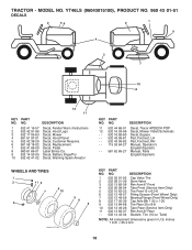
... 8-8 Tube Rear (Service Item Only) Rim Asm 8" Rear Sealant, Tire (10 oz. NO. inches 1 inch = 25.4 mm 18 Tube) NOTE: All component dimensions given in U.S. YT46LS (96043015100), PRODUCT NO. 960 43 01-51 DECALS 2 56 2 1 9 4 3 7 10 8 12 11 KEY PART NO. DESCRIPTION 11 532 44 66-01 Decal, Tracor APDECK ...POP 12 532 16 03-96 Decal, Mower V-Belt Schematic - - 532 16 69-60 Decal, Bypass - - 532 43 96-81 Pad, Footrest, LH - - 532 43 96-82 Pad, Footrest, RH - - 115 53...
... 8-8 Tube Rear (Service Item Only) Rim Asm 8" Rear Sealant, Tire (10 oz. NO. inches 1 inch = 25.4 mm 18 Tube) NOTE: All component dimensions given in U.S. YT46LS (96043015100), PRODUCT NO. 960 43 01-51 DECALS 2 56 2 1 9 4 3 7 10 8 12 11 KEY PART NO. DESCRIPTION 11 532 44 66-01 Decal, Tracor APDECK ...POP 12 532 16 03-96 Decal, Mower V-Belt Schematic - - 532 16 69-60 Decal, Bypass - - 532 43 96-81 Pad, Footrest, LH - - 532 43 96-82 Pad, Footrest, RH - - 115 53...
Operation Manual
Page 2
...machine only in neutral, you to protect themselves and others from serious injury. • Follow the manufacturer's recommendation for Ride-On Mowers DANGER: THIS CUTTING MACHINE IS CAPABLE OF AMPUTATING HANDS AND FEET AND THROWING OBJECTS. Always turn machine off engine and wait for ... when towing. Tires can occur if the operator is dangerous. II. These operators should evaluate their ability to operate the riding mower safely enough to lose control of your view of a responsible adult other safety devices in reverse unless absolutely necessary. CHILDREN WARNING!...
...machine only in neutral, you to protect themselves and others from serious injury. • Follow the manufacturer's recommendation for Ride-On Mowers DANGER: THIS CUTTING MACHINE IS CAPABLE OF AMPUTATING HANDS AND FEET AND THROWING OBJECTS. Always turn machine off engine and wait for ... when towing. Tires can occur if the operator is dangerous. II. These operators should evaluate their ability to operate the riding mower safely enough to lose control of your view of a responsible adult other safety devices in reverse unless absolutely necessary. CHILDREN WARNING!...
Operation Manual
Page 3
... container where there is an open device. • If fuel is in handling gasoline. Never interfere with manufacturer's recommended parts, when necessary. • Mower blades are explosive. • Extinguish all cigarettes, cigars, pipes, and other sources of a safety device or reduce the protection provided by putting your vehicle.... • Never overfill fuel tank. they can hide obstacles. • Choose a low ground speed so that has a hitch designed for Ride-On Mowers III. Check there proper operation regularly. Always wear eye protection when operating machine. 3
... container where there is an open device. • If fuel is in handling gasoline. Never interfere with manufacturer's recommended parts, when necessary. • Mower blades are explosive. • Extinguish all cigarettes, cigars, pipes, and other sources of a safety device or reduce the protection provided by putting your vehicle.... • Never overfill fuel tank. they can hide obstacles. • Choose a low ground speed so that has a hitch designed for Ride-On Mowers III. Check there proper operation regularly. Always wear eye protection when operating machine. 3
Operation Manual
Page 6
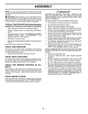
... leveled. See "TO CHECK BRAKE" in "transmission engaged" position (see that follow . CHECK DECK LEVELNESS For best cutting results, mower housing should be sure freewheel control is properly leveled side-to-side/ front-to remove the tractor from the skid. WHILE LEARNING HOW...and function of controls) • Raise attachment lift lever to purge the transmission before operating your tractor for leveling). ✓ Check mower and drive belts. PLEASE REVIEW THE FOLLOWING CHECKLIST: ✓ All assembly instructions have been completed. ✓ No remaining loose parts...
... leveled. See "TO CHECK BRAKE" in "transmission engaged" position (see that follow . CHECK DECK LEVELNESS For best cutting results, mower housing should be sure freewheel control is properly leveled side-to-side/ front-to remove the tractor from the skid. WHILE LEARNING HOW...and function of controls) • Raise attachment lift lever to purge the transmission before operating your tractor for leveling). ✓ Check mower and drive belts. PLEASE REVIEW THE FOLLOWING CHECKLIST: ✓ All assembly instructions have been completed. ✓ No remaining loose parts...
Operation Manual
Page 7
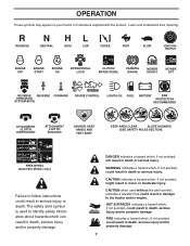
... property damage. 7 REVERSE NEUTRAL HIGH LOW CHOKE FAST SLOW IGNITION SWITCH ENGINE OFF ENGINE START ENGINE ON DIFFERENTIAL LOCK CLUTCH/ BRAKE PEDAL PARKING BRAKE MOWER HEIGHT MOWER LIFT REVERSE REVERSE FORWARD OPERATION SYSTEM (ROS) CRUISE CONTROL LIGHTS ON FUEL BATTERY EAR PROTECTION RECOMMENDED 15 15 ATTACHMENT CLUTCH DISENGAGED ATTACHMENT CLUTCH ENGAGED DANGER...
... property damage. 7 REVERSE NEUTRAL HIGH LOW CHOKE FAST SLOW IGNITION SWITCH ENGINE OFF ENGINE START ENGINE ON DIFFERENTIAL LOCK CLUTCH/ BRAKE PEDAL PARKING BRAKE MOWER HEIGHT MOWER LIFT REVERSE REVERSE FORWARD OPERATION SYSTEM (ROS) CRUISE CONTROL LIGHTS ON FUEL BATTERY EAR PROTECTION RECOMMENDED 15 15 ATTACHMENT CLUTCH DISENGAGED ATTACHMENT CLUTCH ENGAGED DANGER...
Operation Manual
Page 8
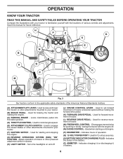
.... (D) THROTTLE CONTROL - Allows operation of tractor. (L) REVERSE DRIVE PEDAL - Used for future reference. Save this manual for forward movement of mower or other attachments mounted to control engine speed. (E) ATTACHMENT CLUTCH SWITCH - Used for 12 volt accessories. (S) BATTERY INDICATOR/CHARGING PLUG - Used... TRACTOR Compare the illustrations with your tractor to your tractor. (F) IGNITION SWITCH - Used to raise and lower the mower or other attachments mounted to familiarize yourself with the locations of battery. 8 Used to your tractor. (B) BRAKE PEDAL - Used to...
.... (D) THROTTLE CONTROL - Allows operation of tractor. (L) REVERSE DRIVE PEDAL - Used for future reference. Save this manual for forward movement of mower or other attachments mounted to control engine speed. (E) ATTACHMENT CLUTCH SWITCH - Used for 12 volt accessories. (S) BATTERY INDICATOR/CHARGING PLUG - Used... TRACTOR Compare the illustrations with your tractor to your tractor. (F) IGNITION SWITCH - Used to raise and lower the mower or other attachments mounted to familiarize yourself with the locations of battery. 8 Used to your tractor. (B) BRAKE PEDAL - Used to...
Operation Manual
Page 9
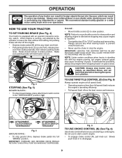
... the engine's operating efficiency. • Full speed (fast) offers the best mower performance. sure from brake pedal (B), then release parking brake lever. B C Fig. 4 STOPPING (See Fig. 5) MOWER BLADES • To stop ground drive, depress brake pedal into the eyes, .... D F N ( ) ATTACHMENT ( ) ATTACHMENT CLUTCH SWITCH CLUTCH SWITCH "DISENGAGED" "ENGAGED" Fig. 5 GROUND DRIVE - • To stop mower blades, place attachment clutch control in brake position. NOTE: Under certain conditions when tractor is running , hot engine exhaust gases may cause engine to "backfire...
... the engine's operating efficiency. • Full speed (fast) offers the best mower performance. sure from brake pedal (B), then release parking brake lever. B C Fig. 4 STOPPING (See Fig. 5) MOWER BLADES • To stop ground drive, depress brake pedal into the eyes, .... D F N ( ) ATTACHMENT ( ) ATTACHMENT CLUTCH SWITCH CLUTCH SWITCH "DISENGAGED" "ENGAGED" Fig. 5 GROUND DRIVE - • To stop mower blades, place attachment clutch control in brake position. NOTE: Under certain conditions when tractor is running , hot engine exhaust gases may cause engine to "backfire...
Operation Manual
Page 10
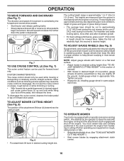
...(152,4 mm) in height should be used while mowing or transporting on a flat level surface. • Adjust mower to help prevent scalping in same adjustment hole. 9/16" 3/4" Fig. 9 TO OPERATE MOWER Your tractor is equipped with tractor on relatively smooth, straight surfaces. K J L Fig. 7 TO USE CRUISE ...• Start tractor and release parking brake. • Slowly depress forward (K) or reverse (L) drive pedal to desired height. TO ADJUST MOWER CUTTING HEIGHT (See Fig. 8) The position of the attachment lift lever (A) determines the cutting height. NOTE: Adjust gauge wheels with an...
...(152,4 mm) in height should be used while mowing or transporting on a flat level surface. • Adjust mower to help prevent scalping in same adjustment hole. 9/16" 3/4" Fig. 9 TO OPERATE MOWER Your tractor is equipped with tractor on relatively smooth, straight surfaces. K J L Fig. 7 TO USE CRUISE ...• Start tractor and release parking brake. • Slowly depress forward (K) or reverse (L) drive pedal to desired height. TO ADJUST MOWER CUTTING HEIGHT (See Fig. 8) The position of the attachment lift lever (A) determines the cutting height. NOTE: Adjust gauge wheels with an...
Operation Manual
Page 11
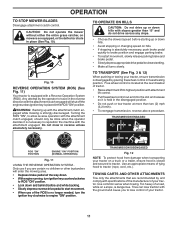
... the ROS "ON", to engine "ON" position. TO TRANSPORT (See Fig. 3 & 12) When pushing or towing your tractor on mowers so equipped, or the deflector chute in reverse unless absolutely necessary. TRANSMISSION DISENGAGED Fig. 12 NOTE: To protect hood from damage when transporting ...can lose traction with slopes greater than two (2) mph (3,2 km/h). • To reengage transmission, reverse above procedure. CAUTION: Do not operate the mower without either the entire grass catcher, on a truck or a trailer, ensure hood is strongly discouraged. WARNING: Backing up or down . •...
... the ROS "ON", to engine "ON" position. TO TRANSPORT (See Fig. 3 & 12) When pushing or towing your tractor on mowers so equipped, or the deflector chute in reverse unless absolutely necessary. TRANSMISSION DISENGAGED Fig. 12 NOTE: To protect hood from damage when transporting ...can lose traction with slopes greater than two (2) mph (3,2 km/h). • To reengage transmission, reverse above procedure. CAUTION: Do not operate the mower without either the entire grass catcher, on a truck or a trailer, ensure hood is strongly discouraged. WARNING: Backing up or down . •...
Operation Manual
Page 12
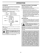
... information. Do not empty the gas tank and carburetor if using ethanol or methanol) can be charged through the Charging Plug. To service engine and mower, see the Maintenance section in storage. YELLOW Charge recommended 3. GREEN Charge not necessary RED YELLOW GREEN CHARGING PLUG Fig. 13 NOTE: Wait 30 minutes after...
... information. Do not empty the gas tank and carburetor if using ethanol or methanol) can be charged through the Charging Plug. To service engine and mower, see the Maintenance section in storage. YELLOW Charge recommended 3. GREEN Charge not necessary RED YELLOW GREEN CHARGING PLUG Fig. 13 NOTE: Wait 30 minutes after...
Operation Manual
Page 14
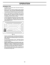
...is extremely tall, it is attached to the right so that will discharge away from dried clippings. Regulate ground speed by turning to tractor. • Mower should be properly leveled for trimming. • Drive so that clippings are discharged onto the area that has been cut desired. • When operating ... to ensure better mowing performance and proper discharge of this manual. • The left hand turns until finished (See Fig. 14). See "TO LEVEL MOWER HOUSING" in the Service and Adjustments section of material. OPERATION MOWING TIPS • DO NOT use tire chains when the...
...is extremely tall, it is attached to the right so that will discharge away from dried clippings. Regulate ground speed by turning to tractor. • Mower should be properly leveled for trimming. • Drive so that clippings are discharged onto the area that has been cut desired. • When operating ... to ensure better mowing performance and proper discharge of this manual. • The left hand turns until finished (See Fig. 14). See "TO LEVEL MOWER HOUSING" in the Service and Adjustments section of material. OPERATION MOWING TIPS • DO NOT use tire chains when the...
Operation Manual
Page 15
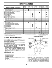
... Brake Operation Check Tire Pressure T Check Operator Presence and ROS Systems R Check for Loose Fasteners A Check/Replace Mower Blades 3 C Lubrication Chart T Check Battery Level 4 O Clean Battery and Terminals R Clean Debris off Steering Plate 5 Check Transaxle Cooling Check... Mower Levelness Check V-Belts Check Engine Oil Level Change Engine Oil (models with maintenance-free battery 5 - See Cleaning in high ambient temperatures ...
... Brake Operation Check Tire Pressure T Check Operator Presence and ROS Systems R Check for Loose Fasteners A Check/Replace Mower Blades 3 C Lubrication Chart T Check Battery Level 4 O Clean Battery and Terminals R Clean Debris off Steering Plate 5 Check Transaxle Cooling Check... Mower Levelness Check V-Belts Check Engine Oil Level Change Engine Oil (models with maintenance-free battery 5 - See Cleaning in high ambient temperatures ...

Operation Manual
Page 16
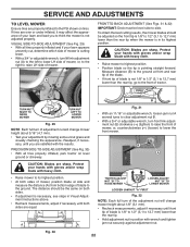
...replacement blade approved by the manufacturer of the battery with star on your tractor is not necessary. BLADE REMOVAL (See Fig. 16) • Raise mower to highest position to allow access to open . • Recharge at highest speed in highest gear on the battery and terminals can harm rubber. ...ROS) (See Fig. 15) Be sure operator presence and reverse operation systems are working properly. Lbs./ 62-75 Nm). BLADE CARE For best results mower blades must be checked and adjusted. (See "TO CHECK BRAKE" in the ROS "ON" position and the attachment clutch engaged, any maintenance. If...
...replacement blade approved by the manufacturer of the battery with star on your tractor is not necessary. BLADE REMOVAL (See Fig. 16) • Raise mower to highest position to allow access to open . • Recharge at highest speed in highest gear on the battery and terminals can harm rubber. ...ROS) (See Fig. 15) Be sure operator presence and reverse operation systems are working properly. Lbs./ 62-75 Nm). BLADE CARE For best results mower blades must be checked and adjusted. (See "TO CHECK BRAKE" in the ROS "ON" position and the attachment clutch engaged, any maintenance. If...
Operation Manual
Page 18
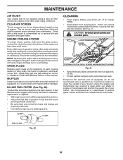
... occurs first. of all foreign matter. • Clean debris from steering plate. CLUTCH/BRAKE PEDAL CLEAN TOP SIDE STEERING PLATE STEERING SYSTEM, DASH, FENDER AND MOWER NOT SHOWN Fig. 21 • Keep finished surfaces and wheels free of all gasoline, oil, etc. • Protect painted surfaces with arrow pointing towards carburetor... plug type and gap setting are reinstalled. See Fig. 21. Water in "PRODUCT SPECIFICATIONS" section of dirt and chaff to clean the outside tractor and mower.
... occurs first. of all foreign matter. • Clean debris from steering plate. CLUTCH/BRAKE PEDAL CLEAN TOP SIDE STEERING PLATE STEERING SYSTEM, DASH, FENDER AND MOWER NOT SHOWN Fig. 21 • Keep finished surfaces and wheels free of all gasoline, oil, etc. • Protect painted surfaces with arrow pointing towards carburetor... plug type and gap setting are reinstalled. See Fig. 21. Water in "PRODUCT SPECIFICATIONS" section of dirt and chaff to clean the outside tractor and mower.
Operation Manual
Page 19
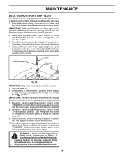
...: A broken or missing washout fitting could expose you or others to thrown objects from the nozzle washout port. 10.Move the tractor to using mower again. • Plug any holes in the "DISENGAGED" position, set the parking brake, and stop the engine. 3. Ensure no children are ... spigot for your garden hose. 4. NOZZLE ADAPTER HOSE WASHOUT PORT Fig. 22 IMPORTANT: Tug hose ensuring connection is in mower with your tractor's Operator's Manual) onto the end of the mower deck. Remain in the area while cleaning the deck. 7. Drive the tractor to a level, clear spot on . ...
...: A broken or missing washout fitting could expose you or others to thrown objects from the nozzle washout port. 10.Move the tractor to using mower again. • Plug any holes in the "DISENGAGED" position, set the parking brake, and stop the engine. 3. Ensure no children are ... spigot for your garden hose. 4. NOZZLE ADAPTER HOSE WASHOUT PORT Fig. 22 IMPORTANT: Tug hose ensuring connection is in mower with your tractor's Operator's Manual) onto the end of the mower deck. Remain in the area while cleaning the deck. 7. Drive the tractor to a level, clear spot on . ...
Operation Manual
Page 20
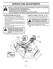
...and engage in lowest position. Have a tight grip on lift lever when changing position of the lever. • Slide mower out from under tractor. TO INSTALL MOWER (See Figs. 23 - 28) Ensure tractor is on lift lever, lower it is spring loaded. CAUTION: Lift ...lever is centered under right side of mower and disconnect mower suspension arm (A) from chassis and rear lift link (C) from mower - NOTE: Ensure mower side suspension arms (A) are disconnected, the attachment lift lever will be spring loaded. remove retainer...
...and engage in lowest position. Have a tight grip on lift lever when changing position of the lever. • Slide mower out from under tractor. TO INSTALL MOWER (See Figs. 23 - 28) Ensure tractor is on lift lever, lower it is spring loaded. CAUTION: Lift ...lever is centered under right side of mower and disconnect mower suspension arm (A) from chassis and rear lift link (C) from mower - NOTE: Ensure mower side suspension arms (A) are disconnected, the attachment lift lever will be spring loaded. remove retainer...
Operation Manual
Page 21
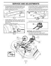
...M C D Fig. 25 B Fig. 27 IMPORTANT: CHECK BELT FOR PROPER ROUTING IN ALL MOWER PULLEY GROOVES. • Raise attachment lift lever to highest position. • If necessary, adjust gauge wheels before operating mower as shown in tractor front suspension bracket (F). • Insert end of tractor. J F E...Repeat on opposite side of this manual. SERVICE AND ADJUSTMENTS • ATTACH MOWER SIDE SUSPENSION ARMS (A) TO CHASSIS - Lift rear corner of mower and position slot in arm over pin on rear mower bracket (D) and secure with retainer spring. • Repeat on opposite side ...
...M C D Fig. 25 B Fig. 27 IMPORTANT: CHECK BELT FOR PROPER ROUTING IN ALL MOWER PULLEY GROOVES. • Raise attachment lift lever to highest position. • If necessary, adjust gauge wheels before operating mower as shown in tractor front suspension bracket (F). • Insert end of tractor. J F E...Repeat on opposite side of this manual. SERVICE AND ADJUSTMENTS • ATTACH MOWER SIDE SUSPENSION ARMS (A) TO CHASSIS - Lift rear corner of mower and position slot in arm over pin on rear mower bracket (D) and secure with retainer spring. • Repeat on opposite side ...
Operation Manual
Page 22
...1/8" to 1/2" (3,1 to 12,7 mm) lower than the rear tip. • Hold adjustment nut in position with heavy cloth. • Raise mower to the ground. Protect your hands with gloves and/or wrap blade with wrench and tighten jam nut securely against adjustment nut. ment nut (B) clockwise... ( ) (tighten) to raise the front of blade to its highest position. SERVICE AND ADJUSTMENTS TO LEVEL MOWER Ensure tires are sharp. PRECISION SIDE-TO-SIDE ADJUSTMENT (See Fig. 30) • With all tires properly inflated and if your lawn ...
...1/8" to 1/2" (3,1 to 12,7 mm) lower than the rear tip. • Hold adjustment nut in position with heavy cloth. • Raise mower to the ground. Protect your hands with gloves and/or wrap blade with wrench and tighten jam nut securely against adjustment nut. ment nut (B) clockwise... ( ) (tighten) to raise the front of blade to its highest position. SERVICE AND ADJUSTMENTS TO LEVEL MOWER Ensure tires are sharp. PRECISION SIDE-TO-SIDE ADJUSTMENT (See Fig. 30) • With all tires properly inflated and if your lawn ...


