Owners Manual
Page 2
... doormats, sleds, boards, wires, and other engine parts become extremely hot during operation or while performing an adjustment or repair to a running (except when specifically recommended by the manufacturer for use snow thrower on the ground, away from your snow thrower properly. Know how to service or repair this manual. Handle fuel with extreme care. WARNING: Snow throwers have competent, well-trained technicians and the proper tools to stop the unit...
... doormats, sleds, boards, wires, and other engine parts become extremely hot during operation or while performing an adjustment or repair to a running (except when specifically recommended by the manufacturer for use snow thrower on the ground, away from your snow thrower properly. Know how to service or repair this manual. Handle fuel with extreme care. WARNING: Snow throwers have competent, well-trained technicians and the proper tools to stop the unit...
Owners Manual
Page 3
.... Never use . 14. To clear the chute: 1. Run the machine a few minutes after throwing snow to the auger blades when snow thrower is transported or not in any enclosure. 3. After striking a foreign object, stop the engine (motor) and check immediately for hidden hazards or traffic. 3. Disengage power to prevent freeze-up of the building. Walk; PRODUCT PRODUIT MAINTENANCE LEVEL NIVEAU DE MAINTENANCE SERIAL NUMBER NUMERO DE SERIE 000000000...
.... Never use . 14. To clear the chute: 1. Run the machine a few minutes after throwing snow to the auger blades when snow thrower is transported or not in any enclosure. 3. After striking a foreign object, stop the engine (motor) and check immediately for hidden hazards or traffic. 3. Disengage power to prevent freeze-up of the building. Walk; PRODUCT PRODUIT MAINTENANCE LEVEL NIVEAU DE MAINTENANCE SERIAL NUMBER NUMERO DE SERIE 000000000...
Owners Manual
Page 4
... DISENGAGING THE AUGER BLADES READ AND FOLLOW ALL SAFETY INFORMATION AND INSTRUCTIONS BEFORE USE OF THIS PRODUCT. IMPORTANT: Safety and instruction decals are located near areas of various controls and adjustments. TABLE OF CONTENTS SAFETY RULES 2-3 CUSTOMER RESPONSIBILITIES 3 PRODUCT SPECIFICATIONS 3 SAFETY AND INSTRUCTIONAL DECALS 4 ASSEMBLY 5-7 PRODUCT OVERVIEW 8 OPERATION 9-13 MAINTENANCE 14-18 STORAGE 19 TROUBLESHOOTING 20 WARRANTY 24-27 KNOW YOUR SNOW THROWER READ THIS OWNER'S MANUAL AND ALL...
... DISENGAGING THE AUGER BLADES READ AND FOLLOW ALL SAFETY INFORMATION AND INSTRUCTIONS BEFORE USE OF THIS PRODUCT. IMPORTANT: Safety and instruction decals are located near areas of various controls and adjustments. TABLE OF CONTENTS SAFETY RULES 2-3 CUSTOMER RESPONSIBILITIES 3 PRODUCT SPECIFICATIONS 3 SAFETY AND INSTRUCTIONAL DECALS 4 ASSEMBLY 5-7 PRODUCT OVERVIEW 8 OPERATION 9-13 MAINTENANCE 14-18 STORAGE 19 TROUBLESHOOTING 20 WARRANTY 24-27 KNOW YOUR SNOW THROWER READ THIS OWNER'S MANUAL AND ALL...
Owners Manual
Page 5
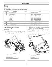
...1. Handle adjustment lever 3. No parts required Qty. Filling the engine with the adjustment levers closed, tighten adjustment handle nuts until the handle feels secure. 3. Upper handle adjustment hole 2 3 Figure 3 1. Rope guide 3. Adjustment lever nut 5 ASSEMBLY Setup Loose Parts Use the chart below to verify that all parts have been shipped. Description No parts required Carriage bolts Flange nuts Washers Knob Chute Deflector Screw 4. NOTE: If handle feels unsecure with oil 1. Use - Recoil handle 2. Procedure 1. 2. 3. Positioning pin 4. Handle 2.
...1. Handle adjustment lever 3. No parts required Qty. Filling the engine with the adjustment levers closed, tighten adjustment handle nuts until the handle feels secure. 3. Upper handle adjustment hole 2 3 Figure 3 1. Rope guide 3. Adjustment lever nut 5 ASSEMBLY Setup Loose Parts Use the chart below to verify that all parts have been shipped. Description No parts required Carriage bolts Flange nuts Washers Knob Chute Deflector Screw 4. NOTE: If handle feels unsecure with oil 1. Use - Recoil handle 2. Procedure 1. 2. 3. Positioning pin 4. Handle 2.
Owners Manual
Page 7
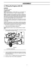
... filler neck and turn clockwise until fully seated. Fill oil to avoid possible engine damage from running low on dipstick with Oil ENGINE See engine manual. Securely screw in increased oil consumption when used for use . Filling the Engine with the recommended oil. 6. Change the oil after each time you check the oil level. 1. Clean around the dipstick (Figure 6). Move the snowthrower to start. Remove either side mounted filler cap dipstick or high oil fill dipstick...
... filler neck and turn clockwise until fully seated. Fill oil to avoid possible engine damage from running low on dipstick with Oil ENGINE See engine manual. Securely screw in increased oil consumption when used for use . Filling the Engine with the recommended oil. 6. Change the oil after each time you check the oil level. 1. Clean around the dipstick (Figure 6). Move the snowthrower to start. Remove either side mounted filler cap dipstick or high oil fill dipstick...
Owners Manual
Page 8
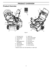
Primer 5. Control bar 13. Oil drain plug 7. Deflector knob 16. Fuel tank cap 4. Electric-start handle 12. Chute deflector 3. Drive side cover 14. Owner's Manual * Dipstick location may vary depending on engine type. *7 13 8 Discharge chute 2. Recoil start button (if equipped) 6. Auger blade 15. Oil fill cap/dipstick 8. Chute rotator handle 11. Choke lever 9. Ignition key 10. PRODUCT OVERVIEW Product Overview 2 1 12 11 4 9 16 3 10 8 *7 6 15 14 5 Figure 7 1.
Primer 5. Control bar 13. Oil drain plug 7. Deflector knob 16. Fuel tank cap 4. Electric-start handle 12. Chute deflector 3. Drive side cover 14. Owner's Manual * Dipstick location may vary depending on engine type. *7 13 8 Discharge chute 2. Recoil start button (if equipped) 6. Auger blade 15. Oil fill cap/dipstick 8. Chute rotator handle 11. Choke lever 9. Ignition key 10. PRODUCT OVERVIEW Product Overview 2 1 12 11 4 9 16 3 10 8 *7 6 15 14 5 Figure 7 1.
Owners Manual
Page 9
... oil level can result in 30 days. Always wear safety glasses or eye shields while operating your snow thrower or performing any snow thrower can result in foreign objects thrown into the filler neck and turn clockwise until fully seated. Filling the Fuel Tank Fill the fuel tank with fuel in the oil filler cap/dipstick. NOTE: Running the engine with high alcohol content can cause hard starting, poor engine...
... oil level can result in 30 days. Always wear safety glasses or eye shields while operating your snow thrower or performing any snow thrower can result in foreign objects thrown into the filler neck and turn clockwise until fully seated. Filling the Fuel Tank Fill the fuel tank with fuel in the oil filler cap/dipstick. NOTE: Running the engine with high alcohol content can cause hard starting, poor engine...
Owners Manual
Page 10
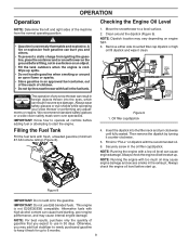
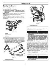
... the primer 2 times with an electric starter, connect an extension cord to the snow thrower and plug the other end into a power source. Excessive priming may not be frozen. Choke lever 3. If the engine does not start the snowthrower. While the engine is damaged, do not use that air cannot escape from the primer hole. The electrical cord can overheat and damage it each time. If the engine does not start the...
... the primer 2 times with an electric starter, connect an extension cord to the snow thrower and plug the other end into a power source. Excessive priming may not be frozen. Choke lever 3. If the engine does not start the snowthrower. While the engine is damaged, do not use that air cannot escape from the primer hole. The electrical cord can overheat and damage it each time. If the engine does not start the...

Owners Manual
Page 11
Wear Areas Stopping the Engine To stop the engine, pull key out (Figure 16). 1 1. Rub Area Figure 15 2. Control bar Disengaging the Auger Blades 1. Figure 13 1. Maximum performance, both snow throwing and driving, occurs when there is zero clearance between the auger blades and the scraper bar. Do not operate without snow or water for the auger blades to the auger blades and scraper bar. This will cause excessive heat...
Wear Areas Stopping the Engine To stop the engine, pull key out (Figure 16). 1 1. Rub Area Figure 15 2. Control bar Disengaging the Auger Blades 1. Figure 13 1. Maximum performance, both snow throwing and driving, occurs when there is zero clearance between the auger blades and the scraper bar. Do not operate without snow or water for the auger blades to the auger blades and scraper bar. This will cause excessive heat...
Owners Manual
Page 13
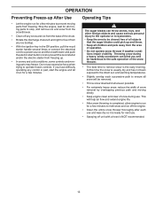
... be hazardous to the safe operation of the snow thrower. • The best time to remove snow is the early morning. The auger blades can blind you have difficulty operating any ice buildup. • With the ignition key in the Off position, pull the recoil starter handle several times or connect the electrical cord to a power source and the snowthrower and push the electric start the engine and let it is...
... be hazardous to the safe operation of the snow thrower. • The best time to remove snow is the early morning. The auger blades can blind you have difficulty operating any ice buildup. • With the ignition key in the Off position, pull the recoil starter handle several times or connect the electrical cord to a power source and the snowthrower and push the electric start the engine and let it is...
Owners Manual
Page 14
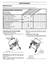
... Clean / Inspect Snow Thrower Clean / Replace V-Belts Check / Replace Auger Blades and Scraper Bar Check Fuel Lines and Electrical Wires Check Engine Oil Level Change Engine Oil Inspect Muffler Check / Replace Spark Plug Empty Fuel Tank Adjusting the Control Cable Checking the Control Cable 1. With the control bar disengaged, unhook and move the control cable to stop properly. Control bar 2. Release the control bar to remove the slack in illustration) Figure 20 1. Position 2 1 3 Figure 19 1. NOTE: You may need to adjust the control cable from the normal operating position...
... Clean / Inspect Snow Thrower Clean / Replace V-Belts Check / Replace Auger Blades and Scraper Bar Check Fuel Lines and Electrical Wires Check Engine Oil Level Change Engine Oil Inspect Muffler Check / Replace Spark Plug Empty Fuel Tank Adjusting the Control Cable Checking the Control Cable 1. With the control bar disengaged, unhook and move the control cable to stop properly. Control bar 2. Release the control bar to remove the slack in illustration) Figure 20 1. Position 2 1 3 Figure 19 1. NOTE: You may need to adjust the control cable from the normal operating position...
Owners Manual
Page 15
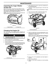
Remove ignition key. 4. Oil drain plug Figure 24 10. Dispose of SJ, SL, or higher. NOTE: Dipstick location may have an Authorized Service Dealer replace the auger blades and the scraper bar (Figure 21). Unscrew and remove the oil fill cap/dipstick. 1 1 2 Figure 21 1. The engine oil will be replaced after extended use. 5. Avoid skin contact with an API service classification of the used oil in -lbs (17 N-m). Run snowthrower until "Full" on...
Remove ignition key. 4. Oil drain plug Figure 24 10. Dispose of SJ, SL, or higher. NOTE: Dipstick location may have an Authorized Service Dealer replace the auger blades and the scraper bar (Figure 21). Unscrew and remove the oil fill cap/dipstick. 1 1 2 Figure 21 1. The engine oil will be replaced after extended use. 5. Avoid skin contact with an API service classification of the used oil in -lbs (17 N-m). Run snowthrower until "Full" on...
Owners Manual
Page 16
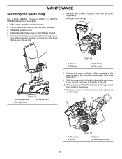
.... 2 3 1 4 3 3 1. Top cover 2. Rear upper cover 16 Screw 2. Top cover 2 2 Figure 25 1. Wait until engine is clear of the rear upper cover and set top cover to the side of the cover disengaging the three clips (Figure 27). 9. Temporarily reinstall oil fill cap to a level surface. 2. Clips Figure 27 3. Carriage bolts 3. MAINTENANCE Servicing the Spark Plug Use a NGK BPR6ES, Champion RN9YC, or BOSCH WR6DC spark plug or equivalent. 1. Unsnap top cover by removing the...
.... 2 3 1 4 3 3 1. Top cover 2. Rear upper cover 16 Screw 2. Top cover 2 2 Figure 25 1. Wait until engine is clear of the rear upper cover and set top cover to the side of the cover disengaging the three clips (Figure 27). 9. Temporarily reinstall oil fill cap to a level surface. 2. Clips Figure 27 3. Carriage bolts 3. MAINTENANCE Servicing the Spark Plug Use a NGK BPR6ES, Champion RN9YC, or BOSCH WR6DC spark plug or equivalent. 1. Unsnap top cover by removing the...
Owners Manual
Page 17
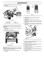
... cover 2. Screw Figure 29 1. Set the gap on the plug to 20-22 ft-lb (27-30 N-m). 20. Remove top oil fill cap. 25. Ignition switch 3. IMPORTANT: The recoil rope will still be attached to primer bulb and electrical wires on back of the primer bulb. 4 2 24 0.030 inch (0.76 mm) Figure 30 1 3 Figure 28 1. Clean around the spark plug. 17. Reattach primer bulb tube to the upper cover. 15. Reattach two screws through the rear covers...
... cover 2. Screw Figure 29 1. Set the gap on the plug to 20-22 ft-lb (27-30 N-m). 20. Remove top oil fill cap. 25. Ignition switch 3. IMPORTANT: The recoil rope will still be attached to primer bulb and electrical wires on back of the primer bulb. 4 2 24 0.030 inch (0.76 mm) Figure 30 1 3 Figure 28 1. Clean around the spark plug. 17. Reattach primer bulb tube to the upper cover. 15. Reattach two screws through the rear covers...
Owners Manual
Page 18
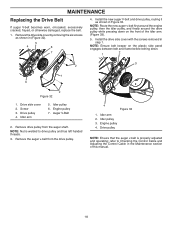
Screw 3. Engine pulley 7. Remove the auger v-belt from the auger shaft. Idler pulley 3. Drive pulley NOTE: Ensure that the auger v-belt is welded to Checking the Control Cable and Adjusting the Control Cable in Figure 33. Install the drive side cover with the screws removed in (Figure 32). 5 4 6 7 4. Auger V-Belt 2. NOTE: Nut is properly adjusted and operating; Remove the drive side cover by removing the six screws as shown in the Maintenance section of the idler arm. (Figure 33). 5. NOTE: Route the new auger v-belt first around the engine pulley,...
Screw 3. Engine pulley 7. Remove the auger v-belt from the auger shaft. Idler pulley 3. Drive pulley NOTE: Ensure that the auger v-belt is welded to Checking the Control Cable and Adjusting the Control Cable in Figure 33. Install the drive side cover with the screws removed in (Figure 32). 5 4 6 7 4. Auger V-Belt 2. NOTE: Nut is properly adjusted and operating; Remove the drive side cover by removing the six screws as shown in the Maintenance section of the idler arm. (Figure 33). 5. NOTE: Route the new auger v-belt first around the engine pulley,...
Owners Manual
Page 19
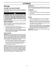
... during storage. ENGINE OIL Drain oil (with engine warm) and replace with a suitable protective cover that all dirt, grease, leaves, etc. Pull recoil starter handle slowly a few times to be used for damage, breakage and wear. Replace if necessary. FUEL SYSTEM IMPORTANT: It is to distribute oil. Do not empty the gas tank and carburetor if using fuel stabilizer. Remove spark plug. 2. store it thoroughly, remove all nuts, bolts, screws, and pins are empty. • Never use engine or carburetor cleaner products...
... during storage. ENGINE OIL Drain oil (with engine warm) and replace with a suitable protective cover that all dirt, grease, leaves, etc. Pull recoil starter handle slowly a few times to be used for damage, breakage and wear. Replace if necessary. FUEL SYSTEM IMPORTANT: It is to distribute oil. Do not empty the gas tank and carburetor if using fuel stabilizer. Remove spark plug. 2. store it thoroughly, remove all nuts, bolts, screws, and pins are empty. • Never use engine or carburetor cleaner products...
Owners Manual
Page 20
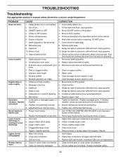
...fresh, clean gasoline. 3. snow. 4. Blocked carburetor air intake. 7. Engine idles or runs roughly 1. Move choke to pull 1. Water in need of this manual. 2. Loose parts or damaged augers or 1. Handles not positioned correctly. 2. Recoil starter is off of this manual. 6. hard to OFF position. 2. Recoil rope should run continuously down from augers / impeller. Check / replace auger v-belt. 4. Motor not running. 2. Start engine. 2. Spark plug wire loose. 1. Fuel tank cap is cool). Remove debris or foreign object from fuel tank to a service center...
...fresh, clean gasoline. 3. snow. 4. Blocked carburetor air intake. 7. Engine idles or runs roughly 1. Move choke to pull 1. Water in need of this manual. 2. Loose parts or damaged augers or 1. Handles not positioned correctly. 2. Recoil starter is off of this manual. 6. hard to OFF position. 2. Recoil rope should run continuously down from augers / impeller. Check / replace auger v-belt. 4. Motor not running. 2. Start engine. 2. Spark plug wire loose. 1. Fuel tank cap is cool). Remove debris or foreign object from fuel tank to a service center...
Owners Manual
Page 24
...of and replaces any defective product or part covered by the Limited Warranty, free of the unit. This Limited Warranty does not cover general maintenance parts and items ("Expendable Parts"), including without limitation spark plugs, bulbs, filters, lubricants, starter cords, belts, blades, and blade adapters. (d) Emissions Control Components. Set-up and pre-delivery service, and engine tune-ups; Preventative maintenance as throttle cable, belt guides adjustments; In addition, you must be submitted and sent to Husqvarna. Certain components (e.g., engines and transmissions) are...
...of and replaces any defective product or part covered by the Limited Warranty, free of the unit. This Limited Warranty does not cover general maintenance parts and items ("Expendable Parts"), including without limitation spark plugs, bulbs, filters, lubricants, starter cords, belts, blades, and blade adapters. (d) Emissions Control Components. Set-up and pre-delivery service, and engine tune-ups; Preventative maintenance as throttle cable, belt guides adjustments; In addition, you must be submitted and sent to Husqvarna. Certain components (e.g., engines and transmissions) are...
Owners Manual
Page 25
... or including any starting fluids; (i) Pressure cleaning or steam cleaning the product; (j) Use of spark plugs other than those meeting emission performance requirements listed in your Husqvarna unit to the use of product, after the repairs have questions concerning this Husqvarna warranty. are NOT covered: (a) Abrasion to mower decks, including sand wear; (b) Damage to cutting equipment by this Limited Warranty, you do not meet Engine manufacturer's specifications; (g) Use of important product...
... or including any starting fluids; (i) Pressure cleaning or steam cleaning the product; (j) Use of spark plugs other than those meeting emission performance requirements listed in your Husqvarna unit to the use of product, after the repairs have questions concerning this Husqvarna warranty. are NOT covered: (a) Abrasion to mower decks, including sand wear; (b) Damage to cutting equipment by this Limited Warranty, you do not meet Engine manufacturer's specifications; (g) Use of important product...
Owners Manual
Page 27
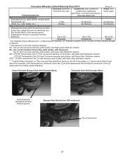
... parts & labor, with Hydro-Gear Distributor network. Consumer Wheeled Limited Warranty Chart 2013 Exhibit A Consumer (personal, Commercial (any commercial, Rental (any household use only) professional, institutional, rental usage) agricultural, or income producing use, Product/Component other than Rental Use) Parts & Accessories (if purchased) Accessories (e.g., grass catcher, bumper guard accessories, etc. 1 Year No Warranty No Warranty Parts (e.g., belts, blades, etc.) 90 days No Warranty No Warranty Parts & Accessories (if replaced in Warranty Service) Replacement parts...
... parts & labor, with Hydro-Gear Distributor network. Consumer Wheeled Limited Warranty Chart 2013 Exhibit A Consumer (personal, Commercial (any commercial, Rental (any household use only) professional, institutional, rental usage) agricultural, or income producing use, Product/Component other than Rental Use) Parts & Accessories (if purchased) Accessories (e.g., grass catcher, bumper guard accessories, etc. 1 Year No Warranty No Warranty Parts (e.g., belts, blades, etc.) 90 days No Warranty No Warranty Parts & Accessories (if replaced in Warranty Service) Replacement parts...


