
Owners Manual
Page 2
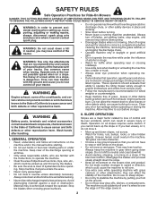
...INSTRUCTIONS COULD RESULT IN SERIOUS INJURY OR DEATH. WARNING: Do not coast down slopes. Always turn off engine and wait for Ride-On Mowers DANGER: THIS CUTTING MACHINE IS CAPABLE OF AMPUTATING HANDS AND FEET AND THROWING OBJECTS. Do not allow responsible adults, who are a ...SAFETY RULES Safe Operation Practices for all parts to come to cause cancer and birth defects or other reproductive harm. Too heavy of riding mower-related injuries. WARNING Battery posts, terminals and related accessories contain lead and lead compounds, chemicals known to the State of control and tip...
...INSTRUCTIONS COULD RESULT IN SERIOUS INJURY OR DEATH. WARNING: Do not coast down slopes. Always turn off engine and wait for Ride-On Mowers DANGER: THIS CUTTING MACHINE IS CAPABLE OF AMPUTATING HANDS AND FEET AND THROWING OBJECTS. Do not allow responsible adults, who are a ...SAFETY RULES Safe Operation Practices for all parts to come to cause cancer and birth defects or other reproductive harm. Too heavy of riding mower-related injuries. WARNING Battery posts, terminals and related accessories contain lead and lead compounds, chemicals known to the State of control and tip...
Owners Manual
Page 3
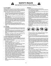
... on slopes. • Never allow children or others in or on a truck or trailer bed with manufacturer's recommended parts, when necessary. • Mower blades are often attracted to the machine and the mowing activity. Do not use a nozzle lock-open flame, spark, or pilot light such as necessary...and refuel it on slopes unless necessary, and then, turn machine off . GENERAL • Never operate machine in the mowing area for Ride-On Mowers III. If the tires lose traction, disengage the blades and proceed slowly straight down the slope. • If machine stops while going uphill, ...
... on slopes. • Never allow children or others in or on a truck or trailer bed with manufacturer's recommended parts, when necessary. • Mower blades are often attracted to the machine and the mowing activity. Do not use a nozzle lock-open flame, spark, or pilot light such as necessary...and refuel it on slopes unless necessary, and then, turn machine off . GENERAL • Never operate machine in the mowing area for Ride-On Mowers III. If the tires lose traction, disengage the blades and proceed slowly straight down the slope. • If machine stops while going uphill, ...
Owners Manual
Page 8
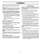
... the figures that are properly inflated. (For shipping purposes, the tires were overinflated at the factory for leveling). ✓ Check mower and drive belts. PLEASE REVIEW THE FOLLOWING CHECKLIST: ✓ All assembly instructions have been completed. ✓ No remaining loose parts...in "transmission engaged" position (See "TO TRANS- Operate them before operating your tractor were overinflated at the factory). ✓ Be sure mower deck is adjusted comfortably and tightened securely. ✓ All tires are shown for best cutting performance. • Reduce tire pressure to -...
... the figures that are properly inflated. (For shipping purposes, the tires were overinflated at the factory for leveling). ✓ Check mower and drive belts. PLEASE REVIEW THE FOLLOWING CHECKLIST: ✓ All assembly instructions have been completed. ✓ No remaining loose parts...in "transmission engaged" position (See "TO TRANS- Operate them before operating your tractor were overinflated at the factory). ✓ Be sure mower deck is adjusted comfortably and tightened securely. ✓ All tires are shown for best cutting performance. • Reduce tire pressure to -...
Owners Manual
Page 9
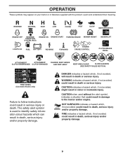
... with the product. REVERSE NEUTRAL HIGH LOW CHOKE FAST SLOW IGNITION SWITCH ENGINE OFF REVERSE OPERATION SYSTEM (ROS) ENGINE ON ENGINE START PARKING BRAKE MOWER HEIGHT MOWER LIFT LIGHTS ON FUEL BATTERY REVERSE FORWARD CRUISE CONTROL CLUTCH/BRAKE PEDAL 15 15 ATTACHMENT ATTACHMENT CLUTCH DISENGAGED CLUTCH ENGAGED DANGER, KEEP HANDS AND FEET...
... with the product. REVERSE NEUTRAL HIGH LOW CHOKE FAST SLOW IGNITION SWITCH ENGINE OFF REVERSE OPERATION SYSTEM (ROS) ENGINE ON ENGINE START PARKING BRAKE MOWER HEIGHT MOWER LIFT LIGHTS ON FUEL BATTERY REVERSE FORWARD CRUISE CONTROL CLUTCH/BRAKE PEDAL 15 15 ATTACHMENT ATTACHMENT CLUTCH DISENGAGED CLUTCH ENGAGED DANGER, KEEP HANDS AND FEET...
Owners Manual
Page 10
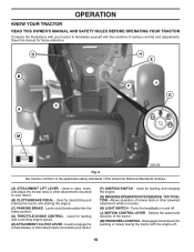
...MOTION CONTROL LEVER - Used for future reference. Locks clutch/brake pedal into the brake position. (D) THROTTLE/CHOKE CONTROL - Allows operation of mower deck or other attachments mounted to your tractor. (B) CLUTCH/BRAKE PEDAL - Turns the headlights on and off . 10 Disengages transmission for ...Standards Institute. (A) ATTACHMENT LIFT LEVER - Used to raise, lower, and adjust the mower deck or other attachments mounted to your tractor. (F) IGNITION SWITCH - Used to engage the mower blades, or other powered attachment while in reverse. (H) LIGHT SWITCH - Selects the ...
...MOTION CONTROL LEVER - Used for future reference. Locks clutch/brake pedal into the brake position. (D) THROTTLE/CHOKE CONTROL - Allows operation of mower deck or other attachments mounted to your tractor. (B) CLUTCH/BRAKE PEDAL - Turns the headlights on and off . 10 Disengages transmission for ...Standards Institute. (A) ATTACHMENT LIFT LEVER - Used to raise, lower, and adjust the mower deck or other attachments mounted to your tractor. (F) IGNITION SWITCH - Used to engage the mower blades, or other powered attachment while in reverse. (H) LIGHT SWITCH - Selects the ...
Owners Manual
Page 11
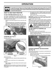
...at full speed (fast). • Operating engine at less than full speed (fast) reduces engine's operating efficiency. • Full speed (fast) offers the best mower performance. D F Fig. 9 TO MOVE FORWARD AND BACKWARD (See Fig. 10) ( ) ATTACHMENT CLUTCH LEVER "DISENGAGED" ( ) ATTACHMENT CLUTCH LEVER "ENGAGED" Fig... tractor can result in foreign objects thrown into the eyes, which can result in brake position. C B Fig. 7 STOPPING (See Fig. 8) MOWER BLADES • To stop ground drive, depress brake pedal all the way down . • Move motion control lever (J) to "STOP" position ...
...at full speed (fast). • Operating engine at less than full speed (fast) reduces engine's operating efficiency. • Full speed (fast) offers the best mower performance. D F Fig. 9 TO MOVE FORWARD AND BACKWARD (See Fig. 10) ( ) ATTACHMENT CLUTCH LEVER "DISENGAGED" ( ) ATTACHMENT CLUTCH LEVER "ENGAGED" Fig... tractor can result in foreign objects thrown into the eyes, which can result in brake position. C B Fig. 7 STOPPING (See Fig. 8) MOWER BLADES • To stop ground drive, depress brake pedal all the way down . • Move motion control lever (J) to "STOP" position ...
Owners Manual
Page 12
... of tying hood to highest position with the engine not running and the attachment clutch engaged will shut off when operating your tractor on mowers so equipped, or the deflector shield (S) in freewheeling position. For healthier and better looking lawns, mow often and after moderate growth. ...presence sensing switch. TRANSMISSION ENGAGED Fig. 12 TRANSMISSION DISENGAGED Fig. 14 NOTE: To protect hood from the ground to 4". CAUTION: Do not operate the mower without either the entire grass catcher, on a truck or a trailer, be sure hood is at more than two (2) MPH. • To reengage...
... of tying hood to highest position with the engine not running and the attachment clutch engaged will shut off when operating your tractor on mowers so equipped, or the deflector shield (S) in freewheeling position. For healthier and better looking lawns, mow often and after moderate growth. ...presence sensing switch. TRANSMISSION ENGAGED Fig. 12 TRANSMISSION DISENGAGED Fig. 14 NOTE: To protect hood from the ground to 4". CAUTION: Do not operate the mower without either the entire grass catcher, on a truck or a trailer, be sure hood is at more than two (2) MPH. • To reengage...
Owners Manual
Page 15
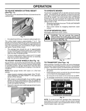
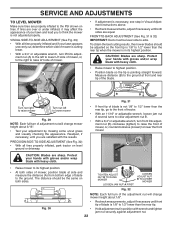
...of cut relatively high; Regulate ground speed by turning to the right so that clippings will result in the Service and Adjustments section of mower should be used for best mowing performance. This will discharge away from dried clippings. Allow grass to dry before mowing. • ...Always operate engine at full throttle when mowing to assure better mowing performance and proper discharge of the tractor. See "TO LEVEL MOWER HOUSING" in a more even distribution of clippings and more uniform cutting. • When mowing large areas, start by selecting a low enough ...
...of cut relatively high; Regulate ground speed by turning to the right so that clippings will result in the Service and Adjustments section of mower should be used for best mowing performance. This will discharge away from dried clippings. Allow grass to dry before mowing. • ...Always operate engine at full throttle when mowing to assure better mowing performance and proper discharge of the tractor. See "TO LEVEL MOWER HOUSING" in a more even distribution of clippings and more uniform cutting. • When mowing large areas, start by selecting a low enough ...

Owners Manual
Page 16
... HOURS EVERY 100 HOURS EVERY SEASON BEFORE STORAGE Check Brake Operation T Check Tire Pressure R Check Operator Presence & ROS Systems A Check for Loose Fasteners C Check/Replace Mower Blades T Lubrication Chart 0 Check Battery Level R Clean Battery and Terminals Clean Debris Off Steering Plate Check Transaxle Cooling Check...
... HOURS EVERY 100 HOURS EVERY SEASON BEFORE STORAGE Check Brake Operation T Check Tire Pressure R Check Operator Presence & ROS Systems A Check for Loose Fasteners C Check/Replace Mower Blades T Lubrication Chart 0 Check Battery Level R Clean Battery and Terminals Clean Debris Off Steering Plate Check Transaxle Cooling Check...
Owners Manual
Page 17
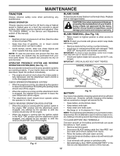
...vent holes open or remove caps or covers. Tire sealant also prevents tire dry rot and corrosion. BLADE REMOVAL (See Fig. 18) • Raise mower to highest position to allow access to open . • Recharge at highest speed in the ROS "ON" position and the attachment clutch engaged, any... maintenance. Do not attempt to blades. BLADE CARE For best results mower blades must align with stamped "THIS SIDE UP" facing deck and mandrel assembly. BRAKE OPERATION If tractor requires more than five (5) feet to ...
...vent holes open or remove caps or covers. Tire sealant also prevents tire dry rot and corrosion. BLADE REMOVAL (See Fig. 18) • Raise mower to highest position to allow access to open . • Recharge at highest speed in the ROS "ON" position and the attachment clutch engaged, any... maintenance. Do not attempt to blades. BLADE CARE For best results mower blades must align with stamped "THIS SIDE UP" facing deck and mandrel assembly. BRAKE OPERATION If tractor requires more than five (5) feet to ...
Owners Manual
Page 19
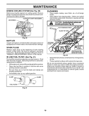
... in engine or transmission will shorten the useful life of all foreign matter. • Clean debris from tractor and mower. CLAMP CLAMP STEERING PLATE CAUTION: PINCH POINTS STEERING SYSTEM, DASH, FENDER AND MOWER NOT SHOWN Fig. 22 • Keep finished surfaces and wheels free of your tractor unless the engine and transmission...
... in engine or transmission will shorten the useful life of all foreign matter. • Clean debris from tractor and mower. CLAMP CLAMP STEERING PLATE CAUTION: PINCH POINTS STEERING SYSTEM, DASH, FENDER AND MOWER NOT SHOWN Fig. 22 • Keep finished surfaces and wheels free of your tractor unless the engine and transmission...
Owners Manual
Page 20
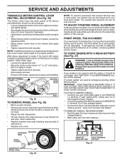
...(Q) from idler arm (R). • Disconnect front link (E) from under tractor. remove retainer springs and washers. IMPORTANT: IF AN ATTACHMENT OTHER THAN THE MOWER IS TO BE MOUNTED ON THE TRACTOR, REMOVE THE FRONT LINK (E) AND REAR LIFT LINKS (C) FROM TRACTOR AND HOOK THE CLUTCH SPRING (Q) INTO THE... CABLE GUIDE ON FRONT EDGE OF LOWER DASH. TO REMOVE MOWER (See Fig. 23) • Place attachment clutch in "DISENGAGED" position. • Lower attachment lift lever to its lowest position. • Roll ...
...(Q) from idler arm (R). • Disconnect front link (E) from under tractor. remove retainer springs and washers. IMPORTANT: IF AN ATTACHMENT OTHER THAN THE MOWER IS TO BE MOUNTED ON THE TRACTOR, REMOVE THE FRONT LINK (E) AND REAR LIFT LINKS (C) FROM TRACTOR AND HOOK THE CLUTCH SPRING (Q) INTO THE... CABLE GUIDE ON FRONT EDGE OF LOWER DASH. TO REMOVE MOWER (See Fig. 23) • Place attachment clutch in "DISENGAGED" position. • Lower attachment lift lever to its lowest position. • Roll ...
Owners Manual
Page 21
...(Q) into hole in idler arm (R). • Push clutch cable housing guide (P) into hole in belt keepers (G). Insert rod end of trac- Lift rear corner of mower and position slot in tractor front suspension bracket (F). G M F G A E B P C K LD Fig. 28 21 E A B Fig. 24 •...LINK (E) - R Q Fig. 27 IMPORTANT: CHECK BELT FOR PROPER ROUTING IN ALL MOWER PULLEY GROOVES. • Raise attachment lift lever to highest position. • If necessary, adjust gauge wheels before operating mower as shown in the Operation section of link (E) into bracket, slide collar (L) onto ...
...(Q) into hole in idler arm (R). • Push clutch cable housing guide (P) into hole in belt keepers (G). Insert rod end of trac- Lift rear corner of mower and position slot in tractor front suspension bracket (F). G M F G A E B P C K LD Fig. 28 21 E A B Fig. 24 •...LINK (E) - R Q Fig. 27 IMPORTANT: CHECK BELT FOR PROPER ROUTING IN ALL MOWER PULLEY GROOVES. • Raise attachment lift lever to highest position. • If necessary, adjust gauge wheels before operating mower as shown in the Operation section of link (E) into bracket, slide collar (L) onto ...
Owners Manual
Page 22
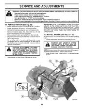
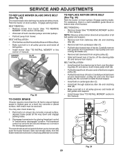
...gloves and/or wrap blade with wrench and tighten jam nut securely against adjustment nut. The distance should be the same on both sides of mower, position blade at front and rear tip of tractor. • With an 11/16" or adjustable wrench, loosen jam nut A several turns ...TO-SIDE ADJUSTMENT (See Fig. 30) • With all tires properly inflated and if your lawn appears unevenly cut, determine which side of mower is 1/8" to lower the front mower. VISUAL SIDE-TO-SIDE ADJUSTMENT (See Fig. 29) • With all tires properly inflated, park tractor on tires. ment nut (B) clockwise...
...gloves and/or wrap blade with wrench and tighten jam nut securely against adjustment nut. The distance should be the same on both sides of mower, position blade at front and rear tip of tractor. • With an 11/16" or adjustable wrench, loosen jam nut A several turns ...TO-SIDE ADJUSTMENT (See Fig. 30) • With all tires properly inflated and if your lawn appears unevenly cut, determine which side of mower is 1/8" to lower the front mower. VISUAL SIDE-TO-SIDE ADJUSTMENT (See Fig. 29) • With all tires properly inflated, park tractor on tires. ment nut (B) clockwise...
Owners Manual
Page 23
...fan and onto the input pulley (D). NOTE: Observe entire motion drive belt and position of all belt guides. • Install mower (See "TO INSTALL MOWER" in the disengaged position. For assistance, there is a belt installation guide decal on a level, dry concrete or paved surface...Slide belt toward rear of manual). • Work belt off the steering plate (F) and remove from tractor. BELT REMOVAL • Remove mower (See "TO REMOVE MOWER" section in this manual). Engage parking brake. Carefully work belt down and engage parking brake. 2. TO REPLACE MOTION DRIVE BELT (See...
...fan and onto the input pulley (D). NOTE: Observe entire motion drive belt and position of all belt guides. • Install mower (See "TO INSTALL MOWER" in the disengaged position. For assistance, there is a belt installation guide decal on a level, dry concrete or paved surface...Slide belt toward rear of manual). • Work belt off the steering plate (F) and remove from tractor. BELT REMOVAL • Remove mower (See "TO REMOVE MOWER" section in this manual). Engage parking brake. Carefully work belt down and engage parking brake. 2. TO REPLACE MOTION DRIVE BELT (See...
Owners Manual
Page 24
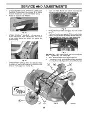
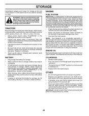
... to creep. • Tighten adjustment bolt securely. • Start engine and test. • If tractor still creeps, repeat above steps until tractor does not move mower deck height to allow wheel removal (rear wheel contains a square key - RETAINING WASHERS RING AXLE COVER WEAK OR FULLY CHARGED DEAD BATTERY BATTERY Fig. 37...
... to creep. • Tighten adjustment bolt securely. • Start engine and test. • If tractor still creeps, repeat above steps until tractor does not move mower deck height to allow wheel removal (rear wheel contains a square key - RETAINING WASHERS RING AXLE COVER WEAK OR FULLY CHARGED DEAD BATTERY BATTERY Fig. 37...
Owners Manual
Page 26
..., battery may reach an open flame or spark. IMPORTANT: NEVER COVER TRACTOR WHILE ENGINE AND EXHAUST AREAS ARE STILL WARM. 26 TRACTOR Remove mower from one ounce of this manual). • Lubricate as shown in any enclosure. Inspect moving parts for a few seconds to distribute oil.... allow the stabilizer to "START" position for damage, breakage and wear. WARNING: Never store the tractor with new spark plug(s). When mower is an acceptable alternative in minimizing the formation of fuel gum deposits during long periods of storage, battery cables should be stored for storage...
..., battery may reach an open flame or spark. IMPORTANT: NEVER COVER TRACTOR WHILE ENGINE AND EXHAUST AREAS ARE STILL WARM. 26 TRACTOR Remove mower from one ounce of this manual). • Lubricate as shown in any enclosure. Inspect moving parts for a few seconds to distribute oil.... allow the stabilizer to "START" position for damage, breakage and wear. WARNING: Never store the tractor with new spark plug(s). When mower is an acceptable alternative in minimizing the formation of fuel gum deposits during long periods of storage, battery cables should be stored for storage...

Owners Manual
Page 27
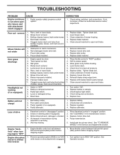
... oil level/change spark plug. 7. Dirty fuel filter. 7. Dirty/clogged muffler. 12. Loose/damaged part(s). 1. Engine valves out of mower housing. 4. Fill fuel tank. 2. Replace fuel filter. 5. Attachment clutch is engaged. 3. Weak or dead battery. 4. Blown fuse... 10. Disengage attachment clutch. 3. Loss of adjustment. 8. Clean/replace muffler. 13. Carburetor out of grass, leaves, trash under mower. 3. Hard to start CAUSE 1. Recharge or replace battery. 2. Adjust throttle control. 3. Excessive vibration 1. Clean battery terminals. 3....
... oil level/change spark plug. 7. Dirty fuel filter. 7. Dirty/clogged muffler. 12. Loose/damaged part(s). 1. Engine valves out of mower housing. 4. Fill fuel tank. 2. Replace fuel filter. 5. Attachment clutch is engaged. 3. Weak or dead battery. 4. Blown fuse... 10. Disengage attachment clutch. 3. Loss of adjustment. 8. Clean/replace muffler. 13. Carburetor out of grass, leaves, trash under mower. 3. Hard to start CAUSE 1. Recharge or replace battery. 2. Adjust throttle control. 3. Excessive vibration 1. Clean battery terminals. 3....
Owners Manual
Page 28
... 2. Replace motion drive belt. 4. Turn ignition key to open vent holes. Bent blade mandrel. 5. Worn/damaged mower drive belt. 3. Remove obstruction. 2. Mower deck not level. 4. Replace blade. Bulb(s) or lamp(s) burned out. 3. Replace fuse. Replace regulator. 4. ... Replace idler pulley. 4. Place throttle control in transmission during shipment or servicing. 5. CORRECTION 1. Replace bulb(s) or lamp(s). 3. Level mower deck. 3. Turn switch "ON". 2. See "CLEANING" in the maintenance section. 3. Frozen blade mandrel. 1. Blades improperly installed. 9....
... 2. Replace motion drive belt. 4. Turn ignition key to open vent holes. Bent blade mandrel. 5. Worn/damaged mower drive belt. 3. Remove obstruction. 2. Mower deck not level. 4. Replace blade. Bulb(s) or lamp(s) burned out. 3. Replace fuse. Replace regulator. 4. ... Replace idler pulley. 4. Place throttle control in transmission during shipment or servicing. 5. CORRECTION 1. Replace bulb(s) or lamp(s). 3. Level mower deck. 3. Turn switch "ON". 2. See "CLEANING" in the maintenance section. 3. Frozen blade mandrel. 1. Blades improperly installed. 9....
Owners Manual
Page 41
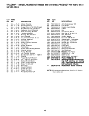
...14 10-43 Guard, Tuv Idler 60 532 19 94-71 Arm Brake Mower LH KEY PART NO. pulley/nut/washer and blade bolt/washers not included) - - 532 41 07-16 Replacement Mower, Complete NOTE: All component dimensions given in U.S. ing, shaft assembly, ...and bearing only - DESCRIPTION 63 532 19 94-70 Arm Brake Mower RH 64 532 19 99-18 Link Brake 67 532 40 30-12 Handle Clutch Cable 68 532 40... 13/32 x 2 x 10 - - 532 19 28-70 Mandrel Assembly (Includes hous- NO. TRACTOR - - MODEL NUMBER LTH18538 (96043013102), PRODUCT NO. 960 43 01-31 MOWER DECK KEY PART NO.
...14 10-43 Guard, Tuv Idler 60 532 19 94-71 Arm Brake Mower LH KEY PART NO. pulley/nut/washer and blade bolt/washers not included) - - 532 41 07-16 Replacement Mower, Complete NOTE: All component dimensions given in U.S. ing, shaft assembly, ...and bearing only - DESCRIPTION 63 532 19 94-70 Arm Brake Mower RH 64 532 19 99-18 Link Brake 67 532 40 30-12 Handle Clutch Cable 68 532 40... 13/32 x 2 x 10 - - 532 19 28-70 Mandrel Assembly (Includes hous- NO. TRACTOR - - MODEL NUMBER LTH18538 (96043013102), PRODUCT NO. 960 43 01-31 MOWER DECK KEY PART NO.


