

Owners Manual
Page 1
English Operator's manual 555FX 555FXT 555RXT 555FRM Please read the operator's manual carefully and make sure you understand the instructions before using the machine.
English Operator's manual 555FX 555FXT 555RXT 555FRM Please read the operator's manual carefully and make sure you understand the instructions before using the machine.

Owners Manual
Page 2
... blades can be thrown violently to the operator or others. Always wear approved protective gloves. Please read the operator's manual carefully and make sure you read and understand the contents of the operator's manual. The blade is capable of output shaft, rpm KEY TO SYMBOLS Only use can be used. Other symbols...
... blades can be thrown violently to the operator or others. Always wear approved protective gloves. Please read the operator's manual carefully and make sure you read and understand the contents of the operator's manual. The blade is capable of output shaft, rpm KEY TO SYMBOLS Only use can be used. Other symbols...
Owners Manual
Page 3
Always use approved hearing protection. WARNING! TWC This label certify that you read the operator's manual carefully. Long-term exposure to noise ! Non-authorized modifications and/or accessories can result in serious personal injury or ... saw blade 17 Fitting the shredder blade and the shredder blade guard (555FRM 17 Fitting other reproductive harm. The engine exhaust from this operator's manual. can cause serious or fatal injury to the operator or others . the design of the machine be performed by the use 32 Maintenance schedule...
Always use approved hearing protection. WARNING! TWC This label certify that you read the operator's manual carefully. Long-term exposure to noise ! Non-authorized modifications and/or accessories can result in serious personal injury or ... saw blade 17 Fitting the shredder blade and the shredder blade guard (555FRM 17 Fitting other reproductive harm. The engine exhaust from this operator's manual. can cause serious or fatal injury to the operator or others . the design of the machine be performed by the use 32 Maintenance schedule...

Owners Manual
Page 4
...is within this machine, make sure that the borrower or buyer gets the operator′s manual, so they will also know how to buy a Husqvarna product! For customer assistance, contact us at our website: www.usa.husqvarna.com 4 - Congratulations on the banks of the Huskvarna River, for the address of.... Today Husqvarna is our wish that you for using , service, maintenance etc) the life span and the second-hand value of your choice to properly maintain and use it will be satisfied with repairs and service whenever this operator′s manual as for a long time. English...
...is within this machine, make sure that the borrower or buyer gets the operator′s manual, so they will also know how to buy a Husqvarna product! For customer assistance, contact us at our website: www.usa.husqvarna.com 4 - Congratulations on the banks of the Huskvarna River, for the address of.... Today Husqvarna is our wish that you for using , service, maintenance etc) the life span and the second-hand value of your choice to properly maintain and use it will be satisfied with repairs and service whenever this operator′s manual as for a long time. English...
Owners Manual
Page 5
... cup 27 Support flange 28 Grass blade 29 Transport guard 30 Allen key 31 Carburettor screwdriver 32 Locking pin 33 Socket spanner 34 Operator's manual 35 Harness English - 5 WHAT IS WHAT?
... cup 27 Support flange 28 Grass blade 29 Transport guard 30 Allen key 31 Carburettor screwdriver 32 Locking pin 33 Socket spanner 34 Operator's manual 35 Harness English - 5 WHAT IS WHAT?

Owners Manual
Page 6
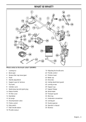
What is what on the brush cutter? (555FX, 555FXT) 1 Locking nut 2 Bevel gear 3 Grease filler cap, bevel gear 4 Shaft 5 Switch for heated handle (555FXT) 6 Throttle control 7 Stop switch 8 Throttle lockout 9 Handle adjustment ... 18 Decompression valve 19 Choke control 20 Support flange 21 Saw blade 22 Drive disc 23 Cutting attachment guard 24 Transport guard 25 Operator's manual 26 Allen key 27 Carburettor screwdriver 28 Locking pin 29 Socket spanner 30 Harness 6 - English WHAT IS WHAT?
What is what on the brush cutter? (555FX, 555FXT) 1 Locking nut 2 Bevel gear 3 Grease filler cap, bevel gear 4 Shaft 5 Switch for heated handle (555FXT) 6 Throttle control 7 Stop switch 8 Throttle lockout 9 Handle adjustment ... 18 Decompression valve 19 Choke control 20 Support flange 21 Saw blade 22 Drive disc 23 Cutting attachment guard 24 Transport guard 25 Operator's manual 26 Allen key 27 Carburettor screwdriver 28 Locking pin 29 Socket spanner 30 Harness 6 - English WHAT IS WHAT?
Owners Manual
Page 7
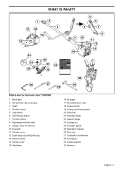
... 18 Choke control 19 Cutting attachment guard 20 Drive disc 21 Shredder blade 22 Support flange 23 Locking nut 24 Transport guard 25 Operator's manual 26 Allen key 27 Carburettor screwdriver 28 Locking pin 29 Socket spanner 30 Harness English - 7 WHAT IS WHAT?
... 18 Choke control 19 Cutting attachment guard 20 Drive disc 21 Shredder blade 22 Support flange 23 Locking nut 24 Transport guard 25 Operator's manual 26 Allen key 27 Carburettor screwdriver 28 Locking pin 29 Socket spanner 30 Harness English - 7 WHAT IS WHAT?

Owners Manual
Page 8
... with medical implants to the operator or others. If you use the machine if you are the cutting attachments we recommend persons with this operator's manual. All covers, guards and handles must also wear approved protective goggles. Listen out for trimming grass, grass clearing and/or forestry clearing. It is only.... Ask your hearing protection as soon as the engine stops. electromagnetic field during operation. IMPORTANT! GLOVES Gloves should be fitted before operating this manual.
... with medical implants to the operator or others. If you use the machine if you are the cutting attachments we recommend persons with this operator's manual. All covers, guards and handles must also wear approved protective goggles. Listen out for trimming grass, grass clearing and/or forestry clearing. It is only.... Ask your hearing protection as soon as the engine stops. electromagnetic field during operation. IMPORTANT! GLOVES Gloves should be fitted before operating this manual.
Owners Manual
Page 33
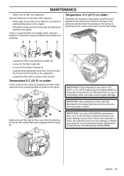
...;lter cover supplied with an air duct (D) that routes the hot air from the winter kit as shown in cold and/or snowy conditions, this manual must be restored to the carburettor • a special air filter with a coarser mesh size (E) Temperature 0°C (32°F) or colder: Fit ...air filter holder using the machine in the figure. Use of other than that the opening on the starter to the carburettor by HUSQVARNA. Special measures are therefore often required: • Partly mask the air inlet on the air duct is a special winter kit available when using...
...;lter cover supplied with an air duct (D) that routes the hot air from the winter kit as shown in cold and/or snowy conditions, this manual must be restored to the carburettor • a special air filter with a coarser mesh size (E) Temperature 0°C (32°F) or colder: Fit ...air filter holder using the machine in the figure. Use of other than that the opening on the starter to the carburettor by HUSQVARNA. Special measures are therefore often required: • Partly mask the air inlet on the air duct is a special winter kit available when using...

Owners Manual
Page 34
... that the locking nut of the cutting equipment is tighten correctly. Replace the trimmer head if necessary. X Clean the outside of the machine. Do this manual. X Check the starter and starter cord. Fill if necessary using a support cup with a catalytic converter). Check and clean the spark arrestor screen on the harness...
... that the locking nut of the cutting equipment is tighten correctly. Replace the trimmer head if necessary. X Clean the outside of the machine. Do this manual. X Check the starter and starter cord. Fill if necessary using a support cup with a catalytic converter). Check and clean the spark arrestor screen on the harness...

Owners Manual
Page 38
...the small nonroad engine owner, you are responsible for presenting your small nonroad engine to a Husqvarna Forest & Garden authorized servicing dealer as soon as defined in the operator's manual. As the small nonroad engine owner, you should contact your nearest authorized servicing dealer or... call Husqvarna Forest & Garden at 1-800-487-5963. If you have any questions regarding your warranty ...
...the small nonroad engine owner, you are responsible for presenting your small nonroad engine to a Husqvarna Forest & Garden authorized servicing dealer as soon as defined in the operator's manual. As the small nonroad engine owner, you should contact your nearest authorized servicing dealer or... call Husqvarna Forest & Garden at 1-800-487-5963. If you have any questions regarding your warranty ...

Workshop Manual
Page 3
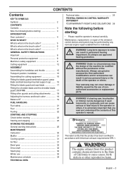
English - 3 Contents Workshop Manual Husqvarna 555, 560XP, 560XPG, 562XP and 562XPG Contents Index 4 Introduction and safety instructions 6 Technical data 10 Service tools 12 Service data 14 Safety equipment 16 Repair instructions 24 Carburettor 34 Troubleshooting 56 Husqvarna AB has a policy of continuous product development and therefore reserves the right to modify the design and appearance of products without prior notice.
English - 3 Contents Workshop Manual Husqvarna 555, 560XP, 560XPG, 562XP and 562XPG Contents Index 4 Introduction and safety instructions 6 Technical data 10 Service tools 12 Service data 14 Safety equipment 16 Repair instructions 24 Carburettor 34 Troubleshooting 56 Husqvarna AB has a policy of continuous product development and therefore reserves the right to modify the design and appearance of products without prior notice.

Workshop Manual
Page 4
... worn starter cord 26 Replacing a broken return spring 27 Starter assembly 27 Stop control 20 Dismantling the stop function 21 Symbols Symbols in the Workshop Manual 9 Symbols on the saw 9 T Tank unit 42 Assembly 43 Dismantling 42 Tank valve 42 Technical Data 10 Threads 54 Repairing damaged threads 54 Throttle control...
... worn starter cord 26 Replacing a broken return spring 27 Starter assembly 27 Stop control 20 Dismantling the stop function 21 Symbols Symbols in the Workshop Manual 9 Symbols on the saw 9 T Tank unit 42 Assembly 43 Dismantling 42 Tank valve 42 Technical Data 10 Threads 54 Repairing damaged threads 54 Throttle control...

Workshop Manual
Page 6
Introduction and safety instructions 2 Introduction and safety regulations Contents 2.1 General ...7 2.2 Safety ...7 2.3 Target group ...7 2.4 Modifications...7 2.5 Tools ...7 2.6 Structure ...7 2.7 Numbering ...7 2.8 General instructions ...8 2.9 Special instructions ...8 2.10 Symbols on the saw ...9 2.11 Symbols in the Workshop Manual 9 6 - English
Introduction and safety instructions 2 Introduction and safety regulations Contents 2.1 General ...7 2.2 Safety ...7 2.3 Target group ...7 2.4 Modifications...7 2.5 Tools ...7 2.6 Structure ...7 2.7 Numbering ...7 2.8 General instructions ...8 2.9 Special instructions ...8 2.10 Symbols on the saw ...9 2.11 Symbols in the Workshop Manual 9 6 - English

Workshop Manual
Page 7
... A new warning symbol decal must be read and understood by all requisite spare parts from the stores. 6. Work forward in the Manual and carry out Cleaning and Inspection in the order set out in the sections. Open the "Repair instructions" chapter which deals with ...in question. 2.5 Tools Special tools are required for use Husqvarna's original: • Spare parts • Service tools • Accessories 2.6 Structure This Workshop Manual can be troubleshoot, repair and test the chain saw. Work forward in the Manual and carry out Dismantling in the order set out in...
... A new warning symbol decal must be read and understood by all requisite spare parts from the stores. 6. Work forward in the Manual and carry out Cleaning and Inspection in the order set out in the sections. Open the "Repair instructions" chapter which deals with ...in question. 2.5 Tools Special tools are required for use Husqvarna's original: • Spare parts • Service tools • Accessories 2.6 Structure This Workshop Manual can be troubleshoot, repair and test the chain saw. Work forward in the Manual and carry out Dismantling in the order set out in...
Workshop Manual
Page 8
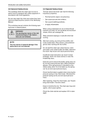
This workshop manual contains the following hazardous properties: • The fluid and its vapour are not followed. 2.9 Special Instructions The fuel used in mind the fire risk. This ... protective gloves when working with local regulations. WARNING! No one may emit sparks, which can fly out and cause personal injury. Risk of this Workshop Manual. When using compressed air, do not touch the muffler until it is to ensure the starter spring does not fly out and cause personal injury...
This workshop manual contains the following hazardous properties: • The fluid and its vapour are not followed. 2.9 Special Instructions The fuel used in mind the fire risk. This ... protective gloves when working with local regulations. WARNING! No one may emit sparks, which can fly out and cause personal injury. Risk of this Workshop Manual. When using compressed air, do not touch the muffler until it is to ensure the starter spring does not fly out and cause personal injury...

Workshop Manual
Page 9
Choke Lever Introduction and safety instructions 2.11 Symbols in the Workshop Manual This symbol warns of personal injury when the instructions are embedded on the saw . Refuelling Stop button Chain oil fill. 2.10 Symbols on the chain saw The symbols below are not followed. Chain brake Decompression valve Fuel pump Adjusting the oil pump English - 9
Choke Lever Introduction and safety instructions 2.11 Symbols in the Workshop Manual This symbol warns of personal injury when the instructions are embedded on the saw . Refuelling Stop button Chain oil fill. 2.10 Symbols on the chain saw The symbols below are not followed. Chain brake Decompression valve Fuel pump Adjusting the oil pump English - 9
Workshop Manual
Page 42
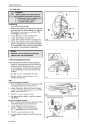
Can cause skin irritation. 3. See the Operator's Manual. Pull out the hoses A to vacuum mode. 4. G 2. Switch the pump to D in "Dismantling the carburettor". 3. After pumping the indicator should stop at max. 7 kPa. Switch ...
Can cause skin irritation. 3. See the Operator's Manual. Pull out the hoses A to vacuum mode. 4. G 2. Switch the pump to D in "Dismantling the carburettor". 3. After pumping the indicator should stop at max. 7 kPa. Switch ...
Workshop Manual
Page 43
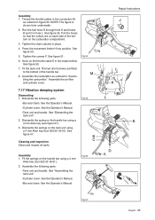
... K and hoses B and C in "Assembling the carburettor". Press the movement limiter H into position. See figure 50. 7. See the Operator's Manual. •Tank unit and handle. See "Dismantling the tank unit". 2. Assembly 1. NOTE! Fit the tank unit. Dismantle the following parts: •...chain. The two short screws are on the carburettor compartment. 3. Fig 54 7.17 Vibration damping system Dismantling 1. See the Operator's Manual. Assembly 1. Assemble the carburettor as outlined in place. 4. See figure 55. Fig 55 Cleaning and inspection Clean and inspect all ...
... K and hoses B and C in "Assembling the carburettor". Press the movement limiter H into position. See figure 50. 7. See the Operator's Manual. •Tank unit and handle. See "Dismantling the tank unit". 2. Assembly 1. NOTE! Fit the tank unit. Dismantle the following parts: •...chain. The two short screws are on the carburettor compartment. 3. Fig 54 7.17 Vibration damping system Dismantling 1. See the Operator's Manual. Assembly 1. Assemble the carburettor as outlined in place. 4. See figure 55. Fig 55 Cleaning and inspection Clean and inspect all ...
Workshop Manual
Page 52
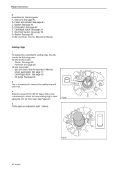
See page 47. E. Electrical System. See page 25. See the Operator's Manual. See page 25. • Flywheel. See page 28. See page 30. • Oil pump. See Figure 81. 4 Fit the parts as outlined in place using ... pull it out. 3 Slide the dowel 575 34 69-01 (figure 80) on the crankcase pin. Fig 80 52 - See page 31. See the Operator's Manual. • Chain guide plate. See page 19. F. On the clutch side: • Bar and chain. Knock the new sealing ring in point 1 above. See page...
See page 47. E. Electrical System. See page 25. See the Operator's Manual. See page 25. • Flywheel. See page 28. See page 30. • Oil pump. See Figure 81. 4 Fit the parts as outlined in place using ... pull it out. 3 Slide the dowel 575 34 69-01 (figure 80) on the crankcase pin. Fig 80 52 - See page 31. See the Operator's Manual. • Chain guide plate. See page 19. F. On the clutch side: • Bar and chain. Knock the new sealing ring in point 1 above. See page...

