
Owners Manual
Page 3
... starting 23 Starting and stopping 23 WORKING TECHNIQUES General working instructions 25 MAINTENANCE Carburetor 30 Muffler 31 Cooling system 31 Air filter 31 Bevel gear 32 Drive shaft 32 Spark plug 32 Winter use of nonauthorized accessories or replacement parts. Your warranty may not cover damage or liability caused by any nonroad engine repair establishment or individual. TWC This label certify that you read the operator's manual...
... starting 23 Starting and stopping 23 WORKING TECHNIQUES General working instructions 25 MAINTENANCE Carburetor 30 Muffler 31 Cooling system 31 Air filter 31 Bevel gear 32 Drive shaft 32 Spark plug 32 Winter use of nonauthorized accessories or replacement parts. Your warranty may not cover damage or liability caused by any nonroad engine repair establishment or individual. TWC This label certify that you read the operator's manual...
Owners Manual
Page 5
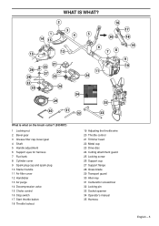
...;ller cap, bevel gear 4 Shaft 5 Handle adjustment 6 Support eyes for harness 7 Fuel tank 8 Cylinder cover 9 Spark plug cap and spark plug 10 Starter handle 11 Air filter cover 12 Handlebar 13 Air purge 14 Decompression valve 15 Choke control 16 Stop switch 17 Start throttle button 18 Throttle lockout 19 Adjusting the throttle wire 20 Throttle control 21 Trimmer head 22 Metal cup 23 Drive disc 24 Cutting attachment guard 25 Locking screw 26 Support cup 27 Support flange 28 Grass blade 29 Transport guard 30 Allen key 31 Carburettor screwdriver 32 Locking pin...
...;ller cap, bevel gear 4 Shaft 5 Handle adjustment 6 Support eyes for harness 7 Fuel tank 8 Cylinder cover 9 Spark plug cap and spark plug 10 Starter handle 11 Air filter cover 12 Handlebar 13 Air purge 14 Decompression valve 15 Choke control 16 Stop switch 17 Start throttle button 18 Throttle lockout 19 Adjusting the throttle wire 20 Throttle control 21 Trimmer head 22 Metal cup 23 Drive disc 24 Cutting attachment guard 25 Locking screw 26 Support cup 27 Support flange 28 Grass blade 29 Transport guard 30 Allen key 31 Carburettor screwdriver 32 Locking pin...

Owners Manual
Page 6
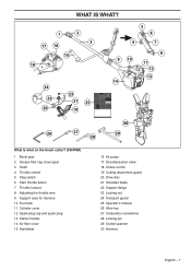
... the brush cutter? (555FX, 555FXT) 1 Locking nut 2 Bevel gear 3 Grease filler cap, bevel gear 4 Shaft 5 Switch for heated handle (555FXT) 6 Throttle control 7 Stop switch 8 Throttle lockout 9 Handle adjustment 10 Support eyes for harness 11 Fuel tank 12 Cylinder cover 13 Spark plug cap and spark plug 14 Starter handle 15 Air filter cover 16 Handlebar 17 Air purge 18 Decompression valve 19 Choke control 20 Support flange 21 Saw blade 22 Drive disc 23 Cutting attachment guard 24 Transport guard 25 Operator's manual 26 Allen key 27 Carburettor screwdriver 28 Locking pin 29...
... the brush cutter? (555FX, 555FXT) 1 Locking nut 2 Bevel gear 3 Grease filler cap, bevel gear 4 Shaft 5 Switch for heated handle (555FXT) 6 Throttle control 7 Stop switch 8 Throttle lockout 9 Handle adjustment 10 Support eyes for harness 11 Fuel tank 12 Cylinder cover 13 Spark plug cap and spark plug 14 Starter handle 15 Air filter cover 16 Handlebar 17 Air purge 18 Decompression valve 19 Choke control 20 Support flange 21 Saw blade 22 Drive disc 23 Cutting attachment guard 24 Transport guard 25 Operator's manual 26 Allen key 27 Carburettor screwdriver 28 Locking pin 29...
Owners Manual
Page 7
... the brush cutter? (555FRM) 1 Bevel gear 2 Grease filler cap, bevel gear 3 Shaft 4 Throttle control 5 Stop switch 6 Start throttle button 7 Throttle lockout 8 Adjusting the throttle wire 9 Support eyes for harness 10 Fuel tank 11 Cylinder cover 12 Spark plug cap and spark plug 13 Starter handle 14 Air filter cover 15 Handlebar 16 Air purge 17 Decompression valve 18 Choke control 19 Cutting attachment guard 20 Drive disc 21 Shredder blade 22 Support flange 23 Locking nut 24 Transport guard 25 Operator's manual 26 Allen key 27 Carburettor screwdriver 28 Locking pin 29...
... the brush cutter? (555FRM) 1 Bevel gear 2 Grease filler cap, bevel gear 3 Shaft 4 Throttle control 5 Stop switch 6 Start throttle button 7 Throttle lockout 8 Adjusting the throttle wire 9 Support eyes for harness 10 Fuel tank 11 Cylinder cover 12 Spark plug cap and spark plug 13 Starter handle 14 Air filter cover 15 Handlebar 16 Air purge 17 Decompression valve 18 Choke control 19 Cutting attachment guard 20 Drive disc 21 Shredder blade 22 Support flange 23 Locking nut 24 Transport guard 25 Operator's manual 26 Allen key 27 Carburettor screwdriver 28 Locking pin 29...

Owners Manual
Page 9
... positions. See instructions under the heading Start. Always wear heavy, long pants. If you must contact your machine. This is positioned on the machine requires special training. Never use a machine with steel toe-caps and non-slip sole. When you release the handle the throttle control and the throttle lockout both move freely and that the cutting attachment stops and remains at the idle setting...
... positions. See instructions under the heading Start. Always wear heavy, long pants. If you must contact your machine. This is positioned on the machine requires special training. Never use a machine with steel toe-caps and non-slip sole. When you release the handle the throttle control and the throttle lockout both move freely and that the cutting attachment stops and remains at the idle setting...
Owners Manual
Page 11
... from the user. The exhaust fumes from the teeth of the saw blade nut, there is fitted with a spark arrestor screen this kind of cutting attachment. Locking nut A locking nut is securely attached to overheat and may be cleaned regularly. Regularly check that your machine is a risk of injury from the engine are correctly positioned. You should therefore always ensure that the muffler is used to allow...
... from the user. The exhaust fumes from the teeth of the saw blade nut, there is fitted with a spark arrestor screen this kind of cutting attachment. Locking nut A locking nut is securely attached to overheat and may be cleaned regularly. Regularly check that your machine is a risk of injury from the engine are correctly positioned. You should therefore always ensure that the muffler is used to allow...

Owners Manual
Page 12
... start to the instructions on Technical data. Grass blades and grass cutters are intended for ballbearing-mounted support cups. before you can turn it . The lock screw must not be so worn that the cutting attachment has stopped completely and disconnect the HT lead from the spark plug before doing any work on approx. 10 times. Follow our instructions and use the recommended file gauge. The lining...
... start to the instructions on Technical data. Grass blades and grass cutters are intended for ballbearing-mounted support cups. before you can turn it . The lock screw must not be so worn that the cutting attachment has stopped completely and disconnect the HT lead from the spark plug before doing any work on approx. 10 times. Follow our instructions and use the recommended file gauge. The lining...

Owners Manual
Page 16
... fitted incorrectly it rests against the blade. Tighten the lock screw (N) in the tool kit. Always use a cutting ! N E F WARNING! Never use the recommended guard for the cutting attachment you are to be used the machine must remain inside the gear housing to lock the shaft. • Position the blade (D) with the correct handlebar, blade guard and harness. Note that the support cup will also come loose, which could result in...
... fitted incorrectly it rests against the blade. Tighten the lock screw (N) in the tool kit. Always use a cutting ! N E F WARNING! Never use the recommended guard for the cutting attachment you are to be used the machine must remain inside the gear housing to lock the shaft. • Position the blade (D) with the correct handlebar, blade guard and harness. Note that the support cup will also come loose, which could result in...

Owners Manual
Page 23
... choke position. Replace the trimmer head or trimmer guard if they have a locking force of serious personal injury. The complete clutch cover ! and shaft must be 35-50 Nm. • Check that the support flange is cracked. • Ensure the locking nut has not lost its original position. Choke: Set the choke control (A) in the working area, otherwise there is started the valve will automatically return to its original setting. The diaphragm need...
... choke position. Replace the trimmer head or trimmer guard if they have a locking force of serious personal injury. The complete clutch cover ! and shaft must be 35-50 Nm. • Check that the support flange is cracked. • Ensure the locking nut has not lost its original position. Choke: Set the choke control (A) in the working area, otherwise there is started the valve will automatically return to its original setting. The diaphragm need...

Owners Manual
Page 24
... throttle function is started ! the throttle will start setting. English with heating elements in either the choke or start throttle positions the cutting attachment will automatically disengage from the start to rotate immediately. return choke control to idle, press the throttle lockout and throttle trigger again. 555FX, 555FXT Starting WARNING! Heated handles 555FXT Models equipped with the choke in the handles have heating elements that automatically maintain a temperature of the starter handle when the cord is turned on...
... throttle function is started ! the throttle will start setting. English with heating elements in either the choke or start throttle positions the cutting attachment will automatically disengage from the start to rotate immediately. return choke control to idle, press the throttle lockout and throttle trigger again. 555FX, 555FXT Starting WARNING! Heated handles 555FXT Models equipped with the choke in the handles have heating elements that automatically maintain a temperature of the starter handle when the cord is turned on...

Owners Manual
Page 31
... operator. See chapter on the cylinder. 4 Cylinder cover (directs cold air over the cylinder). On mufflers without a catalytic converter the screen should clean the screen at idle speed. Never use and remain so for some time after stopping. Remember the risk of : CAUTION! MAINTENANCE 3 If the start throttle speed is too high (above 6500 rpm), turn the adjuster screw A anti-clockwise until the cutting attachment starts to rotate. Then turn adjuster screw...
... operator. See chapter on the cylinder. 4 Cylinder cover (directs cold air over the cylinder). On mufflers without a catalytic converter the screen should clean the screen at idle speed. Never use and remain so for some time after stopping. Remember the risk of : CAUTION! MAINTENANCE 3 If the start throttle speed is too high (above 6500 rpm), turn the adjuster screw A anti-clockwise until the cutting attachment starts to rotate. Then turn adjuster screw...

Owners Manual
Page 32
... need to start or runs poorly at the factory. English Never use HUSQVARNA filter oil, art. Spark plug The spark plug condition is filled with grease. CAUTION! Always use Running problems can damage the piston/ cylinder. The filter must be replaced with a suppressor. The drive shaft must therefore be greased every three months during full-time use for a long time cannot be replaced. The spark plug should check that the electrode gap is used...
... need to start or runs poorly at the factory. English Never use HUSQVARNA filter oil, art. Spark plug The spark plug condition is filled with grease. CAUTION! Always use Running problems can damage the piston/ cylinder. The filter must be replaced with a suppressor. The drive shaft must therefore be greased every three months during full-time use for a long time cannot be replaced. The spark plug should check that the electrode gap is used...
Owners Manual
Page 33
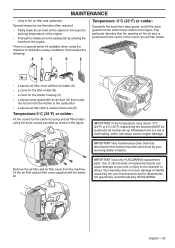
... normal set-up. Special measures are therefore often required: • Partly mask the air inlet on the air duct is positioned in the centre of replacement parts can cause severe engine damage. Fit the air filter and air filter cover supplied with a coarser mesh size (E) Temperature 0°C (32°F) or colder: Fit the covers for the starter housing and air filter holder using the...
... normal set-up. Special measures are therefore often required: • Partly mask the air inlet on the air duct is positioned in the centre of replacement parts can cause severe engine damage. Fit the air filter and air filter cover supplied with a coarser mesh size (E) Temperature 0°C (32°F) or colder: Fit the covers for the starter housing and air filter holder using the...

Owners Manual
Page 34
... full with a suppressor. X Clean the air filter. X Check that the locking nut of the machine. X Check the starter and starter cord. Check that the handle and handlebar are tight. Replace the trimmer head if necessary. Remove it can be carried out by an autorized service workshop. Replace if necessary. Lubricate the drive shaft with bearings. X Check that the X spark plug is undamaged and not cracked. X Clean or replace the spark arrestor screen on the muffl...
... full with a suppressor. X Clean the air filter. X Check that the locking nut of the machine. X Check the starter and starter cord. Check that the handle and handlebar are tight. Replace the trimmer head if necessary. Remove it can be carried out by an autorized service workshop. Replace if necessary. Lubricate the drive shaft with bearings. X Check that the X spark plug is undamaged and not cracked. X Clean or replace the spark arrestor screen on the muffl...

Owners Manual
Page 38
... in your Operator′s Manual. CONSEQUENTIAL DAMAGES Husqvarna Forest & Garden may deny you . EMISSION CONTROL WARRANTY PARTS LIST 1 Carburetor and internal parts 2 Intake pipe, airfilter holder and carburetor bolts. 3 Airfilter and fuelfilter covered up to maintenance schedule. 4 Ignition System 1Spark Plug, covered up to the first scheduled replacement point for that Husqvarna Forest & Garden may be warranted for the period of time up to maintenance schedule...
... in your Operator′s Manual. CONSEQUENTIAL DAMAGES Husqvarna Forest & Garden may deny you . EMISSION CONTROL WARRANTY PARTS LIST 1 Carburetor and internal parts 2 Intake pipe, airfilter holder and carburetor bolts. 3 Airfilter and fuelfilter covered up to maintenance schedule. 4 Ignition System 1Spark Plug, covered up to the first scheduled replacement point for that Husqvarna Forest & Garden may be warranted for the period of time up to maintenance schedule...
Workshop Manual
Page 4
... Service tools 12 Starter 25, 26 Cleaning and inspection 25 Cleaning and inspection: 26 Dismantling the starter 25 Replacing a broken or worn starter cord 26 Replacing a broken return spring 27 Starter assembly 27 Stop control 20 Dismantling the stop function 21 Symbols Symbols in the Workshop Manual 9 Symbols on the saw 9 T Tank unit 42 Assembly 43 Dismantling 42 Tank valve 42 Technical Data 10 Threads 54 Repairing damaged threads 54 Throttle control lock, throttle lock and spring...
... Service tools 12 Starter 25, 26 Cleaning and inspection 25 Cleaning and inspection: 26 Dismantling the starter 25 Replacing a broken or worn starter cord 26 Replacing a broken return spring 27 Starter assembly 27 Stop control 20 Dismantling the stop function 21 Symbols Symbols in the Workshop Manual 9 Symbols on the saw 9 T Tank unit 42 Assembly 43 Dismantling 42 Tank valve 42 Technical Data 10 Threads 54 Repairing damaged threads 54 Throttle control lock, throttle lock and spring...

Workshop Manual
Page 7
... assembling the chain saw will be gradually introduced into ongoing production. Work forward in the Manual and carry out Cleaning and Inspection in the order set out in the sections. 3. Usage is to be read together with the Starter and carry out the instructions outlined under Cleaning and Inspection. 4. A description of repairing and servicing chain saws. The position references and figure numbers restart English - 7 All service tools...
... assembling the chain saw will be gradually introduced into ongoing production. Work forward in the Manual and carry out Cleaning and Inspection in the order set out in the sections. 3. Usage is to be read together with the Starter and carry out the instructions outlined under Cleaning and Inspection. 4. A description of repairing and servicing chain saws. The position references and figure numbers restart English - 7 All service tools...
Workshop Manual
Page 8
... air, do not touch the muffler until it is to ensure the starter spring does not fly out and cause personal injury. Air can penetrate into the blood stream, which cause ignition. This box warns of personal injury if the instructions are not followed. Insufficient chain lubrication can result in relevant places. The chain saw may repair the chain saw unless the bar, chain and clutch cover (chain brake...
... air, do not touch the muffler until it is to ensure the starter spring does not fly out and cause personal injury. Air can penetrate into the blood stream, which cause ignition. This box warns of personal injury if the instructions are not followed. Insufficient chain lubrication can result in relevant places. The chain saw may repair the chain saw unless the bar, chain and clutch cover (chain brake...

Workshop Manual
Page 29
... crankshaft pin. See figure 11. Fit the intake system as outlined in "7.14 Assembling the intake system", the tank unit as outlined in "7.16 tank unit", and the air filter as outlined in the crankcase. Fit the cabling to the stop . • The starter, at a tightening torque of 2.5-3.5 Nm • The cylinder cover Fig 13 Repair Instructions English - 29 Remove the plastic air gap tool. Turn...
... crankshaft pin. See figure 11. Fit the intake system as outlined in "7.14 Assembling the intake system", the tank unit as outlined in "7.16 tank unit", and the air filter as outlined in the crankcase. Fit the cabling to the stop . • The starter, at a tightening torque of 2.5-3.5 Nm • The cylinder cover Fig 13 Repair Instructions English - 29 Remove the plastic air gap tool. Turn...

Workshop Manual
Page 57
... carburettor pump side is loose Floods when the Worn needle/needle tip engine is not Control system set too high running Control system sticking Worn needle/needle tip Leaking diaphragm/cover plate Worn lever arm in the control system Faulty diffuser jet Uneven idling Blocked fuel filter Blocked fuel line Leaking inlet hose (rubber) Loose carburettor mounting Worn throttle valve axle Loose throttle valve screw Worn throttle valve Leaking control system (air or fuel) The control...
... carburettor pump side is loose Floods when the Worn needle/needle tip engine is not Control system set too high running Control system sticking Worn needle/needle tip Leaking diaphragm/cover plate Worn lever arm in the control system Faulty diffuser jet Uneven idling Blocked fuel filter Blocked fuel line Leaking inlet hose (rubber) Loose carburettor mounting Worn throttle valve axle Loose throttle valve screw Worn throttle valve Leaking control system (air or fuel) The control...


