Installation Guide
Page 1
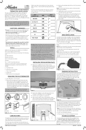
...other to 7 p.m. aspx/ for mounting 1 - Turn off the power to your Furnace by using the switch on the Hunter wallplate. Thermostat Cover Labeling Wires * Using the chart below, label the wires one hand. Doing so could cause damage to your heating/cooling system. Step 2-1. 2-2. W G Y RH RC Steps .... Note: If you through the opening on the wall plate. 44660/44668 Programmable Thermostat Installation This easy installation guide will walk you have any addition wires that do not match with the wiring diagrams in the Accessory Pack. Verify that the wall plate is ...
...other to 7 p.m. aspx/ for mounting 1 - Turn off the power to your Furnace by using the switch on the Hunter wallplate. Thermostat Cover Labeling Wires * Using the chart below, label the wires one hand. Doing so could cause damage to your heating/cooling system. Step 2-1. 2-2. W G Y RH RC Steps .... Note: If you through the opening on the wall plate. 44660/44668 Programmable Thermostat Installation This easy installation guide will walk you have any addition wires that do not match with the wiring diagrams in the Accessory Pack. Verify that the wall plate is ...
Installation Guide
Page 2
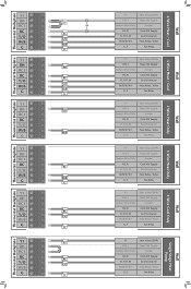
Thermostat Backplate Thermostat Backplate Thermostat Backplate Thermostat Backplate Thermostat Backplate Thermostat Backplate Y1 RH RC1 RC Y/O W/B G Y1 RH RC1 RC Y/O W/B G Y1 RH RC1 RC Y/O W/B G Y1 RH RC1 RC Y/O W/B G Y1 RH RC1 RC Y/O W/B G Y1 RH RC1 RC Y/O W/B G RHC OR RC Y/O W/B G RH RC Y/O W/B G RH W/B RC W/B G RC Y/O G Y1 RC Y/O G Y1 RH, 4 Jumper Wire... Only RC, R O, Y/O, M W/B, W, W1 G, F Heat Valve (SSHP) Heat 24V Supply Jumper Cool 24V Supply Cool Contactor Heat Relay / Valve Fan Relay Y1 RH, 4 Jumper Wire Only RC, R O, Y/O, M W/B, W, W1 G, ...
Thermostat Backplate Thermostat Backplate Thermostat Backplate Thermostat Backplate Thermostat Backplate Thermostat Backplate Y1 RH RC1 RC Y/O W/B G Y1 RH RC1 RC Y/O W/B G Y1 RH RC1 RC Y/O W/B G Y1 RH RC1 RC Y/O W/B G Y1 RH RC1 RC Y/O W/B G Y1 RH RC1 RC Y/O W/B G RHC OR RC Y/O W/B G RH RC Y/O W/B G RH W/B RC W/B G RC Y/O G Y1 RC Y/O G Y1 RH, 4 Jumper Wire... Only RC, R O, Y/O, M W/B, W, W1 G, F Heat Valve (SSHP) Heat 24V Supply Jumper Cool 24V Supply Cool Contactor Heat Relay / Valve Fan Relay Y1 RH, 4 Jumper Wire Only RC, R O, Y/O, M W/B, W, W1 G, ...
User Guide
Page 2
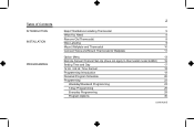
Table of Contents INTRODUCTION INSTALLATION PROGRAMMING 2 Read This Before Installing Thermostat 5 What You Need 8 Remove Old Thermostat 8 Wire Labeling 9 Mount Wallplate and Thermostat 10 Connect Wires and Mount Thermostat to Wallplate 11 Option Menu 13 Remote Sensor Channel Set-Up (does not apply to thermostat model 44660) 15 Setting Time and Day 17 12 Hr. / 24 Hr. Time Format...
Table of Contents INTRODUCTION INSTALLATION PROGRAMMING 2 Read This Before Installing Thermostat 5 What You Need 8 Remove Old Thermostat 8 Wire Labeling 9 Mount Wallplate and Thermostat 10 Connect Wires and Mount Thermostat to Wallplate 11 Option Menu 13 Remote Sensor Channel Set-Up (does not apply to thermostat model 44660) 15 Setting Time and Day 17 12 Hr. / 24 Hr. Time Format...
User Guide
Page 5
...installation is designed to install or operate your thermostat. These have 24 volt or millivolt control systems and represent most gas, oil, electric, or 2-wire hot water heating and air conditioning systems. ...It will not control 120/240 Volt systems or millivolt systems. COMPRESSOR PROTECTION 5The thermostat provides a 3.5 minute delay after...Owner's Manual thoroughly before it can be restarted. This thermostat will also operate single-stage heat pumps that do not have auxiliary or emergency heat. ...
...installation is designed to install or operate your thermostat. These have 24 volt or millivolt control systems and represent most gas, oil, electric, or 2-wire hot water heating and air conditioning systems. ...It will not control 120/240 Volt systems or millivolt systems. COMPRESSOR PROTECTION 5The thermostat provides a 3.5 minute delay after...Owner's Manual thoroughly before it can be restarted. This thermostat will also operate single-stage heat pumps that do not have auxiliary or emergency heat. ...
User Guide
Page 8
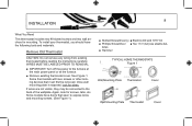
... #8 slotted screws and two wall anchors for screws, tabs, etc. teries ■ Hammer TYPICAL HOME THERMOSTATS Figure 1 Wall Mounting Plate Thermostat Cover Wall Mounting Plate Thermostat Cover Some thermostats will have screws or other locking devices that open to expose wires and mounting screws. (See Figure 1). ■ Slotted Screwdriver(s) ■ Electric drill and 3/16" bit...
... #8 slotted screws and two wall anchors for screws, tabs, etc. teries ■ Hammer TYPICAL HOME THERMOSTATS Figure 1 Wall Mounting Plate Thermostat Cover Wall Mounting Plate Thermostat Cover Some thermostats will have screws or other locking devices that open to expose wires and mounting screws. (See Figure 1). ■ Slotted Screwdriver(s) ■ Electric drill and 3/16" bit...
User Guide
Page 9
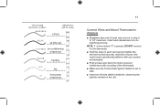
... C, do not always comply with a code letter as shown in wall is larger than necessary for non-battery powered thermostats. ■ After labeling wires, disconnect them to the wall. ■ If hole in Table A on that no hot or cold air can enter the back of ...points is usually marked with the standard. If you may be a Common wire and should not be used only for wires, seal this hole so that thermostat. This wire is used . 9 Wire Labeling ■ Each wire coming from the wall to the existing thermostat is connected to a terminal point on page 11. ■ IMPORTANT! If...
... C, do not always comply with a code letter as shown in wall is larger than necessary for non-battery powered thermostats. ■ After labeling wires, disconnect them to the wall. ■ If hole in Table A on that no hot or cold air can enter the back of ...points is usually marked with the standard. If you may be a Common wire and should not be used only for wires, seal this hole so that thermostat. This wire is used . 9 Wire Labeling ■ Each wire coming from the wall to the existing thermostat is connected to a terminal point on page 11. ■ IMPORTANT! If...
User Guide
Page 10
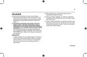
... 2 RC RC1 RH Y1 G Y/O W/B Figure 3 10 Installation Mount Wallplate and Thermostat ■ Remove the wallplate from your existing holes do not line up with those on wall and pull existing wires through large opening . Insert mounting screws provided into wall anchor and tighten. (See ...opening . Mark holes for appearance. Then level for plastic anchors provided if your thermostat by pressing the release tab on the bottom of the thermostat. (See Figure 2.) ■ Position wallplate on the Hunter wallplate. ■ Drill holes with wall. ■ Reposition wallplate to wall,...
... 2 RC RC1 RH Y1 G Y/O W/B Figure 3 10 Installation Mount Wallplate and Thermostat ■ Remove the wallplate from your existing holes do not line up with those on wall and pull existing wires through large opening . Insert mounting screws provided into wall anchor and tighten. (See ...opening . Mark holes for appearance. Then level for plastic anchors provided if your thermostat by pressing the release tab on the bottom of the thermostat. (See Figure 2.) ■ Position wallplate on the Hunter wallplate. ■ Drill holes with wall. ■ Reposition wallplate to wall,...
User Guide
Page 11
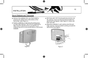
... RC / VC 24 Volt cool RC Y / C* / M / O air conditioning compressor Y/0 W / H / B heating W/B G / F fan G Y1 heat pump compressor Y1 11 Connect Wires and Mount Thermostat to Wallplate ■ Straighten bare end of the thermostat. ■ Make sure the Thermostats System Switch is set to OFF. ■ Insert two AA size alkaline batteries, observing the polarity marked on...
... RC / VC 24 Volt cool RC Y / C* / M / O air conditioning compressor Y/0 W / H / B heating W/B G / F fan G Y1 heat pump compressor Y1 11 Connect Wires and Mount Thermostat to Wallplate ■ Straighten bare end of the thermostat. ■ Make sure the Thermostats System Switch is set to OFF. ■ Insert two AA size alkaline batteries, observing the polarity marked on...


