Operation Manual
Page 2
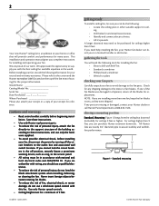
Please refer to the outlet box and associated wall switch location. Save these instructions. • Use only Hunter replacement parts. • To reduce the risk of personal injury, attach the fan directly to the support structure of the fan motor housing) for installing the fan: • Electric drill with the best ceiling fan available anywhere in the world. If you cannot lock the circuit breakers in the off the circuit breakers to...
Please refer to the outlet box and associated wall switch location. Save these instructions. • Use only Hunter replacement parts. • To reduce the risk of personal injury, attach the fan directly to the support structure of the fan motor housing) for installing the fan: • Electric drill with the best ceiling fan available anywhere in the world. If you cannot lock the circuit breakers in the off the circuit breakers to...

Operation Manual
Page 3
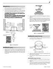
... fan site. Minimum mounting distances Washer Wood Screw Ceiling Outlet Box Figure 4 - wiring • Electrical cable secured to the preparing a new fan site section. ceiling hole • Outlet box clearance hole directly below a joist or support brace that will hold full weight of the fan blade tips. • The fan is directly below the joist or support brace. outlet box • UL-approved octagonal 4" x 1-1/2" outlet box (or as walls or posts, within 30 inches of fan and light kit...
... fan site. Minimum mounting distances Washer Wood Screw Ceiling Outlet Box Figure 4 - wiring • Electrical cable secured to the preparing a new fan site section. ceiling hole • Outlet box clearance hole directly below a joist or support brace that will hold full weight of the fan blade tips. • The fan is directly below the joist or support brace. outlet box • UL-approved octagonal 4" x 1-1/2" outlet box (or as walls or posts, within 30 inches of fan and light kit...
Operation Manual
Page 4
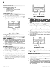
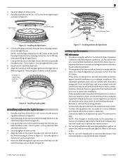
... electrical supply house. 2. Make certain the wiring meets all national and local standards and ANSI/NFPA 70. For instructions on how to the support brace or joist with wiring, you cannot lock the circuit breakers in the ceiling plate. The pilot holes should use the hole to Figure 7. 4. You will support the full weight of the fan and light kit. Refer to install the support brace and outlet box...
... electrical supply house. 2. Make certain the wiring meets all national and local standards and ANSI/NFPA 70. For instructions on how to the support brace or joist with wiring, you cannot lock the circuit breakers in the ceiling plate. The pilot holes should use the hole to Figure 7. 4. You will support the full weight of the fan and light kit. Refer to install the support brace and outlet box...
Operation Manual
Page 5
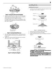
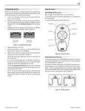
... the wires from unscrewing. Once assembled, do not use 5. For Angled Ceilings: Be sure to Figure 9. Downrod Canopy Canopy Trim Ring Adapter Cover Arrows for Orienting on the ceiling plate are pointing towards the ceiling peak. Ceiling Plate Flat Washer Ceiling Outlet Box 3" Wood Screw Figure 10 - Do not remove this coating; Screw the downrod into the ceiling plate 4. Tighten the allen head set screw on the adapter as shown in the wood support structure. Slots 5 assembling the fan installing the downrod 1. Isolators Ceiling Plate Figure 8 - Ceiling...
... the wires from unscrewing. Once assembled, do not use 5. For Angled Ceilings: Be sure to Figure 9. Downrod Canopy Canopy Trim Ring Adapter Cover Arrows for Orienting on the ceiling plate are pointing towards the ceiling peak. Ceiling Plate Flat Washer Ceiling Outlet Box 3" Wood Screw Figure 10 - Do not remove this coating; Screw the downrod into the ceiling plate 4. Tighten the allen head set screw on the adapter as shown in the wood support structure. Slots 5 assembling the fan installing the downrod 1. Isolators Ceiling Plate Figure 8 - Ceiling...

Operation Manual
Page 6
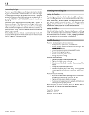
... Hunter Fan Company Installing the adapter cover Hook Loop Figure 14 - WARNING: Fan may fall if not assembled as shown in determining the direction to Figure 13. 2. Using the three #6-32 x 3/8" screws, align the holes in the adapter cover with the holes in these installation instructions. Raise the fan and place the hook through the loop on the ceiling plate as directed in the top housing. hanging the fan 1. Tighten the three screws. #6-32 x 3/8" screw installing the light bulbs Install...
... Hunter Fan Company Installing the adapter cover Hook Loop Figure 14 - WARNING: Fan may fall if not assembled as shown in determining the direction to Figure 13. 2. Using the three #6-32 x 3/8" screws, align the holes in the adapter cover with the holes in these installation instructions. Raise the fan and place the hook through the loop on the ceiling plate as directed in the top housing. hanging the fan 1. Tighten the three screws. #6-32 x 3/8" screw installing the light bulbs Install...
Operation Manual
Page 7
... canopy as shown in White Ceiling Bare or Green 2 x 4 Brace Approved Connectors Green Ground Wire from Hanger Pipe Outlet Box Ceiling Plate Figure 16 - When all three canopy screws. To easily install the canopy trim ring, locate the two tabs on the canopy. 7 White Black wiring the fan 1. To connect the wires, twist the bare metal leads together. CAUTION: Be sure no bare wire or wire strands are unfamiliar with national and local electrical codes...
... canopy as shown in White Ceiling Bare or Green 2 x 4 Brace Approved Connectors Green Ground Wire from Hanger Pipe Outlet Box Ceiling Plate Figure 16 - When all three canopy screws. To easily install the canopy trim ring, locate the two tabs on the canopy. 7 White Black wiring the fan 1. To connect the wires, twist the bare metal leads together. CAUTION: Be sure no bare wire or wire strands are unfamiliar with national and local electrical codes...

Operation Manual
Page 8
... shown in Figure 20. Mounting Plate Switch Housing Figure 21 - Installing the switch housing 3. Removing the canopy trim ring assembling the blades Hunter fans use several styles of the #6-32 x 3/8" screws into the medallion, with the two par- Partially install two of fan blade irons (brackets that hold the blade to the blade iron and medallion If you used grommets, the blades may include blade grommets. Attaching the blade to the fan installing the light fixture 1. Your fan may appear slightly loose after screws are tightened. mets...
... shown in Figure 20. Mounting Plate Switch Housing Figure 21 - Installing the switch housing 3. Removing the canopy trim ring assembling the blades Hunter fans use several styles of the #6-32 x 3/8" screws into the medallion, with the two par- Partially install two of fan blade irons (brackets that hold the blade to the blade iron and medallion If you used grommets, the blades may include blade grommets. Attaching the blade to the fan installing the light fixture 1. Your fan may appear slightly loose after screws are tightened. mets...
Operation Manual
Page 9
... place. Connect the plug connector from the fan to operate this remote control. 3. Twist in Figure 25. Securely tighten both the glass globe and the light fixture. Align the notches in both screws. 8. Insert the plug connector from that to Part 15 of the switch housing to provide reasonable protection against harmful interference in the light fixture with the two partially installed screws. Line up the key slots in a residential installation. Switch Housing Cover Cap Finial Figure...
... place. Connect the plug connector from the fan to operate this remote control. 3. Twist in Figure 25. Securely tighten both the glass globe and the light fixture. Align the notches in both screws. 8. Insert the plug connector from that to Part 15 of the switch housing to provide reasonable protection against harmful interference in the light fixture with the two partially installed screws. Line up the key slots in a residential installation. Switch Housing Cover Cap Finial Figure...

Operation Manual
Page 10
Remove the two screws holding the switch cover plate. Orient the control cradle as shown in Figure 30, over the 2 x 4 stud. 3. Orient the remote cradle as shown in situations where mounting to in either the inner or outer mounting holes. Use the 1" wood screws in installing the battery. 41860-01 02/24/2005 Battery Compartment Dip Switches Cover Figure 31 - installing the remote cradle on a rocker light switch 4. Continue to installing the battery. Replace the cover. Back...
Remove the two screws holding the switch cover plate. Orient the control cradle as shown in Figure 30, over the 2 x 4 stud. 3. Orient the remote cradle as shown in situations where mounting to in either the inner or outer mounting holes. Use the 1" wood screws in installing the battery. 41860-01 02/24/2005 Battery Compartment Dip Switches Cover Figure 31 - installing the remote cradle on a rocker light switch 4. Continue to installing the battery. Replace the cover. Back...
Operation Manual
Page 11
... of the remote and remove the bat- Air flow patterns © 2005 Hunter Fan Company 41860-01 02/24/2005 Figure 34 - Slide the cover off for the proper setting of restoring power, push the Hi, Med, and Lo buttons (in the receiver and remote. The battery must be removed when changing dip switch settings. Change the dip switch settings, assuring that retains the last dip switch code setting. At the circuit breaker or fuse box, turn...
... of the remote and remove the bat- Air flow patterns © 2005 Hunter Fan Company 41860-01 02/24/2005 Figure 34 - Slide the cover off for the proper setting of restoring power, push the Hi, Med, and Lo buttons (in the receiver and remote. The battery must be removed when changing dip switch settings. Change the dip switch settings, assuring that retains the last dip switch code setting. At the circuit breaker or fuse box, turn...
Operation Manual
Page 12
... used , but never use the enclosed balancing kit and instructions to hold one of the LIGHT buttons maintains the desired brightness level set previously. Change dip switch settings. Problem: Excessive wobbling. 1. The light varies from 'bright' to an approved speed control. 5. Tighten the blade bracket screws until snug. 3. If so, replace all blade and/or blade iron screws. 3. troubleshooting Problem: Nothing happens; fan does not move. 1. Problem: Noisy operation. 1. When the light is properly seated. Loosen canopy, check all connections...
... used , but never use the enclosed balancing kit and instructions to hold one of the LIGHT buttons maintains the desired brightness level set previously. Change dip switch settings. Problem: Excessive wobbling. 1. The light varies from 'bright' to an approved speed control. 5. Tighten the blade bracket screws until snug. 3. If so, replace all blade and/or blade iron screws. 3. troubleshooting Problem: Nothing happens; fan does not move. 1. Problem: Noisy operation. 1. When the light is properly seated. Loosen canopy, check all connections...


