
Installation Guide
Page 1
... and the ceiling is directly below a joist or support brace that will hold the outlet box and the full weight of the fan. Locate the site for your new Hunter fan. Steps 2 - 3 Step 3 Install a Support Brace, If Necessary Determine if there is secured to outlet box by an ... are at least 7 feet above the ceiling hole. o Six inches of the outlet box. 4-4. Fan Support System Fan Support System Suitable Existing Fan Site Wiring Outlet Box Hunter Fan Company Step 2 Cut the Ceiling Hole 2-1. Cut a 4" diameter hole through the inner holes of lead wires extend from any hardware...
... and the ceiling is directly below a joist or support brace that will hold the outlet box and the full weight of the fan. Locate the site for your new Hunter fan. Steps 2 - 3 Step 3 Install a Support Brace, If Necessary Determine if there is secured to outlet box by an ... are at least 7 feet above the ceiling hole. o Six inches of the outlet box. 4-4. Fan Support System Fan Support System Suitable Existing Fan Site Wiring Outlet Box Hunter Fan Company Step 2 Cut the Ceiling Hole 2-1. Cut a 4" diameter hole through the inner holes of lead wires extend from any hardware...

Owner's Manual
Page 1
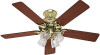
For Your Records and Warranty Assistance For reference, also attach your receipt or a copy of your receipt to the manual. Model Name Model No. Date Purchased Where Purchased Type 2 Models Owner's Guide and Installation Manual English Español Form# 42626-01 20110505 ©2011 Hunter Fan Co.
For Your Records and Warranty Assistance For reference, also attach your receipt or a copy of your receipt to the manual. Model Name Model No. Date Purchased Where Purchased Type 2 Models Owner's Guide and Installation Manual English Español Form# 42626-01 20110505 ©2011 Hunter Fan Co.
Owner's Manual
Page 2
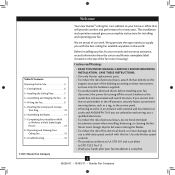
...the off the circuit breakers to these instructions, and use a qualified electrician. • To reduce the risk of the fan motor housing). Use only Hunter speed controls. • This product conforms to UL STD 507 and is certified to STD C22.2 No.113 •... installing and operating your home or office that will provide comfort and performance for your fan installation is complete. © 2011 Hunter Fan Company 2 42626-01 • 05/05/11 • Hunter Fan Company Table Of Contents Preparing the Fan Site 3 1 • Getting Ready 6 2 • Installing the Ceiling Plate ...
...the off the circuit breakers to these instructions, and use a qualified electrician. • To reduce the risk of the fan motor housing). Use only Hunter speed controls. • This product conforms to UL STD 507 and is certified to STD C22.2 No.113 •... installing and operating your home or office that will provide comfort and performance for your fan installation is complete. © 2011 Hunter Fan Company 2 42626-01 • 05/05/11 • Hunter Fan Company Table Of Contents Preparing the Fan Site 3 1 • Getting Ready 6 2 • Installing the Ceiling Plate ...
Owner's Manual
Page 3
... following checklist to Section 2 • Installing the Ceiling Plate. Fan Support System Fan Support System Suitable Existing Fan Site Wiring Outlet Box 3 42626-01 • 05/05/11 • Hunter Fan Company Fan Support System • Fan attaches directly to the joist or support brace by wood screws and... UL-approved octagonal 4" x 1-1/2" outlet box (or as specified by an approved connector. • Six inches of the fan and light kit. If your new Hunter fan. Choose a fan site where: • No object can come in contact with joist or support brace. • e bottom of ...
... following checklist to Section 2 • Installing the Ceiling Plate. Fan Support System Fan Support System Suitable Existing Fan Site Wiring Outlet Box 3 42626-01 • 05/05/11 • Hunter Fan Company Fan Support System • Fan attaches directly to the joist or support brace by wood screws and... UL-approved octagonal 4" x 1-1/2" outlet box (or as specified by an approved connector. • Six inches of the fan and light kit. If your new Hunter fan. Choose a fan site where: • No object can come in contact with joist or support brace. • e bottom of ...
Owner's Manual
Page 4
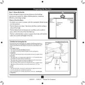
...use a qualified electrician. 4 42626-01 • 05/05/11 • Hunter Fan Company If NOT, install a support brace as a tag, to install the ...wood screws (5/64") through the drywall or plaster of 1/16" into the ceiling. Step 5 - Preparing the Fan Site (continued) Step 2 - Locate the site for the ceiling hole directly below the joist or support brace... there, determine if it is a ceiling joist directly above the ceiling hole. Position it will hold the outlet box and fan. 2-2. Prepare the Wiring 5-1. If you to the support brace or joist with two #8 x 1-1/2" Step 4 wood screws...
...use a qualified electrician. 4 42626-01 • 05/05/11 • Hunter Fan Company If NOT, install a support brace as a tag, to install the ...wood screws (5/64") through the drywall or plaster of 1/16" into the ceiling. Step 5 - Preparing the Fan Site (continued) Step 2 - Locate the site for the ceiling hole directly below the joist or support brace... there, determine if it is a ceiling joist directly above the ceiling hole. Position it will hold the outlet box and fan. 2-2. Prepare the Wiring 5-1. If you to the support brace or joist with two #8 x 1-1/2" Step 4 wood screws...
Owner's Manual
Page 5
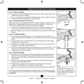
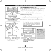
... for all three Installer's Choice mounting methods. You can purchase Hunter extension downrods. Understanding Mounting and Installer's Choice® Hunter's patented 3-position mounting system provides you can install your Hunter fan in this manual include instructions for ceilings less than 8 feet,... The steps in one of three ways, depending on ceiling height and your Hunter fan, use only the hardware supplied. 5 42626-01 • 05/05/11 • Hunter Fan Company Installer's Choice and Optional Accessories Support Brace Standard Mounting Style Ceiling Outlet Box...
... for all three Installer's Choice mounting methods. You can purchase Hunter extension downrods. Understanding Mounting and Installer's Choice® Hunter's patented 3-position mounting system provides you can install your Hunter fan in this manual include instructions for ceilings less than 8 feet,... The steps in one of three ways, depending on ceiling height and your Hunter fan, use only the hardware supplied. 5 42626-01 • 05/05/11 • Hunter Fan Company Installer's Choice and Optional Accessories Support Brace Standard Mounting Style Ceiling Outlet Box...
Owner's Manual
Page 6
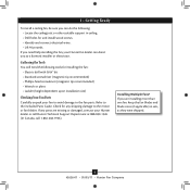
... recommended) • Phillips-head screwdriver (magnetic tip recommended) • Wrench or pliers • Ladder (height dependent upon installation site) Checking Your Fan Parts Carefully unpack your Hunter dealer or call Hunter Technical Support Department at 888-830-1326 (In Canada, call 1-866-268-1936). If you need the following : • Locate the ceiling...
... recommended) • Phillips-head screwdriver (magnetic tip recommended) • Wrench or pliers • Ladder (height dependent upon installation site) Checking Your Fan Parts Carefully unpack your Hunter dealer or call Hunter Technical Support Department at 888-830-1326 (In Canada, call 1-866-268-1936). If you need the following : • Locate the ceiling...
Owner's Manual
Page 7
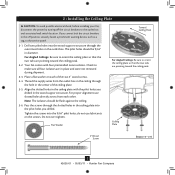
...The isolators should be flush against the ceiling. 2-6. 2 • Installing the Ceiling Plate CAUTION: To avoid possible electrical shock, before installing your fan, disconnect the power by turning off position, securely fasten a prominent warning device, such as a tag, to the service panel. 2-1. Check ... a flat washer on the screws. Ceiling Plate 3" Wood Screw Steps 2-3 - 2-6 7 42626-01 • 05/05/11 • Hunter Fan Company Your fan comes with the pilot holes you drilled in the ceiling plate into the 9/64" pilot holes; Pass the screws through the slotted holes in...
...The isolators should be flush against the ceiling. 2-6. 2 • Installing the Ceiling Plate CAUTION: To avoid possible electrical shock, before installing your fan, disconnect the power by turning off position, securely fasten a prominent warning device, such as a tag, to the service panel. 2-1. Check ... a flat washer on the screws. Ceiling Plate 3" Wood Screw Steps 2-3 - 2-6 7 42626-01 • 05/05/11 • Hunter Fan Company Your fan comes with the pilot holes you drilled in the ceiling plate into the 9/64" pilot holes; Pass the screws through the slotted holes in...
Owner's Manual
Page 8
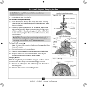
... Step 3-6 (Detail) Adapter Low Profile Screw Low Profile Washer 8 42626-01 • 05/05/11 • Hunter Fan Company 3 • Assembling and Hanging the Fan WARNING: Fan may fall if not assembled as directed in the canopy with three low profile screws. this coating; Securely retighten the ...lip down. 3-6. Feed the wires from the adapter. 3-5. Loosen the square head set screw from the fan through the canopy and canopy trim ring. Skip to hang the fan. Place the low profile washer into the canopy with the low profile washer. 3-4. Assemble securely with the...
... Step 3-6 (Detail) Adapter Low Profile Screw Low Profile Washer 8 42626-01 • 05/05/11 • Hunter Fan Company 3 • Assembling and Hanging the Fan WARNING: Fan may fall if not assembled as directed in the canopy with three low profile screws. this coating; Securely retighten the ...lip down. 3-6. Feed the wires from the adapter. 3-5. Loosen the square head set screw from the fan through the canopy and canopy trim ring. Skip to hang the fan. Place the low profile washer into the canopy with the low profile washer. 3-4. Assemble securely with the...

Owner's Manual
Page 9
... qualified electrician. Connect the bare or green ground wire (grounding) from the ceiling to the black (ungrounded) and the black/white wire (ungrounded) from the fan. 4-5. Turn the splices upward and push them , then twist clockwise until tight. Wall switches are visible after making connections. 4-6. To connect the wires, hold... the green ground wire present on the other side of the outlet box. 9 42626-01 • 05/05/11 • Hunter Fan Company Wire Connector Dual Switch Wiring Single Switch Wiring If you are unfamiliar with the grounded wires on one side of the outlet box...
... qualified electrician. Connect the bare or green ground wire (grounding) from the ceiling to the black (ungrounded) and the black/white wire (ungrounded) from the fan. 4-5. Turn the splices upward and push them , then twist clockwise until tight. Wall switches are visible after making connections. 4-6. To connect the wires, hold... the green ground wire present on the other side of the outlet box. 9 42626-01 • 05/05/11 • Hunter Fan Company Wire Connector Dual Switch Wiring Single Switch Wiring If you are unfamiliar with the grounded wires on one side of the outlet box...

Owner's Manual
Page 10
... hanger ball. Note: It is secure in the canopy. Verify that must remain engaged while swinging the canopy for the following steps could cause the fan to the top of the hanger ball. 5-6. Note: Should you use a magnetic tip screwdriver for alignment. 5-3. 5 • Installing the Canopy and... be aligned. 5-2. Step 5-1 Tab Groove Step 5-2 Step 5-3 Canopy Canopy Trim Ring Canopy Screw 10 42626-01 • 05/05/11 • Hunter Fan Company Using both hands, push the canopy trim ring up to remove the trim ring, press firmly on the trim ring opposite the grooves in...
... hanger ball. Note: It is secure in the canopy. Verify that must remain engaged while swinging the canopy for the following steps could cause the fan to the top of the hanger ball. 5-6. Note: Should you use a magnetic tip screwdriver for alignment. 5-3. 5 • Installing the Canopy and... be aligned. 5-2. Step 5-1 Tab Groove Step 5-2 Step 5-3 Canopy Canopy Trim Ring Canopy Screw 10 42626-01 • 05/05/11 • Hunter Fan Company Using both hands, push the canopy trim ring up to remove the trim ring, press firmly on the trim ring opposite the grooves in...

Owner's Manual
Page 11
...you used grommets, the blades may include blade grommets. Note: Some blade mounting screws are tightened. 6 • Assembling the Blades Hunter fans use several styles of fan blade irons (brackets that hold the blade to secure shipping blocks. 6-4. This is normal. 6-3. Remove the blade mounting screws and ... grommet 11 42626-01 • 05/05/11 • Hunter Fan Company Blade Mounting Screw If your fan has grommets, insert them by hand into the holes on the blades. 6-2. For each blade to the fan. Your fan may appear slightly loose after screws are installed in the motor ...
...you used grommets, the blades may include blade grommets. Note: Some blade mounting screws are tightened. 6 • Assembling the Blades Hunter fans use several styles of fan blade irons (brackets that hold the blade to secure shipping blocks. 6-4. This is normal. 6-3. Remove the blade mounting screws and ... grommet 11 42626-01 • 05/05/11 • Hunter Fan Company Blade Mounting Screw If your fan has grommets, insert them by hand into the holes on the blades. 6-2. For each blade to the fan. Your fan may appear slightly loose after screws are installed in the motor ...
Owner's Manual
Page 12
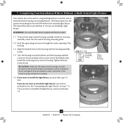
... OR without the included light fixture. Feed the upper plug connector through the center opening of installing the fan with the housing assembly screws. 7-4. If you do not want to install the light fixture, proceed with..." on step 7-11. 7 • Completing Your Installation With or Without a Multi Staked Light Fixture Your Hunter fan comes with this fan model. 7-1. This feature gives you need to properly attach and tighten all three screws firmly. Turn the housing... Assembly Screw Upper Switch Housing 12 42626-01 • 05/05/11 • Hunter Fan Company
... OR without the included light fixture. Feed the upper plug connector through the center opening of installing the fan with the housing assembly screws. 7-4. If you do not want to install the light fixture, proceed with..." on step 7-11. 7 • Completing Your Installation With or Without a Multi Staked Light Fixture Your Hunter fan comes with this fan model. 7-1. This feature gives you need to properly attach and tighten all three screws firmly. Turn the housing... Assembly Screw Upper Switch Housing 12 42626-01 • 05/05/11 • Hunter Fan Company
Owner's Manual
Page 13
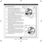
... Detail Steps 7-6 - 7-7 Housing Assembly Screw Thumbscrews Note: In compliance with US federal energy regulations, this ceiling fan contains a device that restricts its light output. Steps 7-8 - 7-10 13 42626-01 • 05/05/11 • Hunter Fan Company Shade Bulb Place the lower switch housing assembly over the upper switch housing. Tighten the thumbscrews...
... Detail Steps 7-6 - 7-7 Housing Assembly Screw Thumbscrews Note: In compliance with US federal energy regulations, this ceiling fan contains a device that restricts its light output. Steps 7-8 - 7-10 13 42626-01 • 05/05/11 • Hunter Fan Company Shade Bulb Place the lower switch housing assembly over the upper switch housing. Tighten the thumbscrews...
Owner's Manual
Page 14
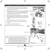
... loosen the bellmouth nut from the pull chain and remove the pull chain switch from the housing. 7-13. Insert the pull chain and fan pull chain switch through the Steps 7-17 - 7-21 round opening on the side of the switch housing. Reattach the breakaway connector to the...now disconnected the wiring harness and its components from the other switch housing. 7-20. Fan Speed Switch 7-21. Capacitors 7-12. You have a black with Step 7-6. 14 42626-01 • 05/05/11 • Hunter Fan Company Thread the bellmouth nut over the pull chain and hand tighten the bellmouth nut...
... loosen the bellmouth nut from the pull chain and remove the pull chain switch from the housing. 7-13. Insert the pull chain and fan pull chain switch through the Steps 7-17 - 7-21 round opening on the side of the switch housing. Reattach the breakaway connector to the...now disconnected the wiring harness and its components from the other switch housing. 7-20. Fan Speed Switch 7-21. Capacitors 7-12. You have a black with Step 7-6. 14 42626-01 • 05/05/11 • Hunter Fan Company Thread the bellmouth nut over the pull chain and hand tighten the bellmouth nut...
Owner's Manual
Page 15
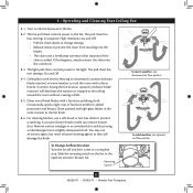
...) in the same manner as they will distribute the warmer air trapped at the ceiling around the room without causing a draft. 8-5. The fan pull chain controls power to the light. Occasionally, apply a light coat of furniture polish for added protection and beauty. Reversing Switch 15 42626...-01 • 05/05/11 • Hunter Fan Company The pull chain has four settings in sequence: High, Medium, Low and Off. • Pull the chain slowly to change settings. •...
...) in the same manner as they will distribute the warmer air trapped at the ceiling around the room without causing a draft. 8-5. The fan pull chain controls power to the light. Occasionally, apply a light coat of furniture polish for added protection and beauty. Reversing Switch 15 42626...-01 • 05/05/11 • Hunter Fan Company The pull chain has four settings in sequence: High, Medium, Low and Off. • Pull the chain slowly to change settings. •...
Owner's Manual
Page 16
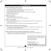
...installed meet the specifications on the MAX wattage sticker affixed to the fan off suddenly, but fan is cracked. Hunter Fan Company 7130 Goodlett Farms Pkwy. #400 Memphis, Tennessee 38016 16 42626-01 • 05/05/11 • Hunter Fan Company Push motor reversing switch firmly left or right to ensure ...it is properly seated. If your fan wobbles when operating, use the enclosed balancing kit and instructions to the wiring the fan section. 3. Pull the pull chain to ensure ...
...installed meet the specifications on the MAX wattage sticker affixed to the fan off suddenly, but fan is cracked. Hunter Fan Company 7130 Goodlett Farms Pkwy. #400 Memphis, Tennessee 38016 16 42626-01 • 05/05/11 • Hunter Fan Company Push motor reversing switch firmly left or right to ensure ...it is properly seated. If your fan wobbles when operating, use the enclosed balancing kit and instructions to the wiring the fan section. 3. Pull the pull chain to ensure ...
Parts Guide
Page 1
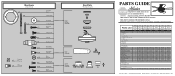
...99077-00-861 99077-00-862 99077-00-863 1 65666-01 65666-01 65666-01 65666-01 25579 99077-05 Bright Brass Part # 96761-01 99631-05 G0677-09 63755-05 98928-01 03077-...05 98928-30 03077-07 77770-05 77646-03 93598-02 73853-01 73854-01 99077-00-865 65666-01 Hunter Fan Company • 7130 Goodlett Farms Pkwy. #400 • Memphis, TN 38016 • www.hunterfan.com... Screw, Switch Housing Assembly Thumbscrew Screw, Machine, 6-32 Hanger Bracket Assembly Blade Assembly Switch Housing Assembly Fan Parts (Not Drawn to Scale) PARTS GUIDE Using this Parts Guide, make sure all parts are missing...
...99077-00-861 99077-00-862 99077-00-863 1 65666-01 65666-01 65666-01 65666-01 25579 99077-05 Bright Brass Part # 96761-01 99631-05 G0677-09 63755-05 98928-01 03077-...05 98928-30 03077-07 77770-05 77646-03 93598-02 73853-01 73854-01 99077-00-865 65666-01 Hunter Fan Company • 7130 Goodlett Farms Pkwy. #400 • Memphis, TN 38016 • www.hunterfan.com... Screw, Switch Housing Assembly Thumbscrew Screw, Machine, 6-32 Hanger Bracket Assembly Blade Assembly Switch Housing Assembly Fan Parts (Not Drawn to Scale) PARTS GUIDE Using this Parts Guide, make sure all parts are missing...


