
Installation Guide
Page 1
... Fan Support System o Fan attaches directly to outlet box by an approved connector. Outlet Box o e outlet box is an UL-approved octagonal 4" x 1-1/2" outlet box (or as specified by wood screws and washers through the inner holes of 1/16" into the ceiling. Wiring o e electrical cable is recessed a minimum of 1/16" into the ceiling. Attach the fan supply line to your new Hunter fan. For instructions to install your ceiling fan site. CAUTION: All wiring...
... Fan Support System o Fan attaches directly to outlet box by an approved connector. Outlet Box o e outlet box is an UL-approved octagonal 4" x 1-1/2" outlet box (or as specified by wood screws and washers through the inner holes of 1/16" into the ceiling. Wiring o e electrical cable is recessed a minimum of 1/16" into the ceiling. Attach the fan supply line to your new Hunter fan. For instructions to install your ceiling fan site. CAUTION: All wiring...
Owner's Manual
Page 1
installation and operation manual for Hunter Ceiling Fans TYPE 2 Models 42775-01 • 04/29/08 For Your Records and Warranty Assistance Model Name Catalog/Model No Serial No Date Purchased Where Purchased For reference also attach your receipt or a copy of your receipt to the manual.
installation and operation manual for Hunter Ceiling Fans TYPE 2 Models 42775-01 • 04/29/08 For Your Records and Warranty Assistance Model Name Catalog/Model No Serial No Date Purchased Where Purchased For reference also attach your receipt or a copy of your receipt to the manual.

Owner's Manual
Page 2
... 1 • Getting Ready 4 2 • Installing the Ceiling Plate 5 3 • Assembling and Hanging the Fan . . . 6 4 • Wiring the Fan 8 5 • Installing the Canopy and Canopy Trim Ring 9 6 • Assembling the Blades 10 7 • Activating Perfect BalanceTM 11 8 • Completing Your Installation With or Without a Bowl Light Fixture . . . . . .12 9 • Operating and Cleaning Your Ceiling Fan 16 10 • Troubleshooting 17 Welcome Your new Hunter® ceiling fan is an addition to your fan, disconnect the power by turning off position, securely...
... 1 • Getting Ready 4 2 • Installing the Ceiling Plate 5 3 • Assembling and Hanging the Fan . . . 6 4 • Wiring the Fan 8 5 • Installing the Canopy and Canopy Trim Ring 9 6 • Assembling the Blades 10 7 • Activating Perfect BalanceTM 11 8 • Completing Your Installation With or Without a Bowl Light Fixture . . . . . .12 9 • Operating and Cleaning Your Ceiling Fan 16 10 • Troubleshooting 17 Welcome Your new Hunter® ceiling fan is an addition to your fan, disconnect the power by turning off position, securely...
Owner's Manual
Page 3
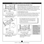
... Box For ceilings higher than 8 feet high CAUTION: To reduce the risk of personal injury, attach the fan directly to the support structure of your preference: Low Profile, Standard, or Angled mounting. Installer's Choice and Optional Accessories Support Brace Standard Mounting Style Ceiling Outlet Box Standard Mounting hangs from the ceiling by a downrod (included). All Hunter fans use the accessories, follow the instructions included with each product. Considering Optional Accessories Consider using Hunter's optional accessories, including a wall-mounted or remote speed control...
... Box For ceilings higher than 8 feet high CAUTION: To reduce the risk of personal injury, attach the fan directly to the support structure of your preference: Low Profile, Standard, or Angled mounting. Installer's Choice and Optional Accessories Support Brace Standard Mounting Style Ceiling Outlet Box Standard Mounting hangs from the ceiling by a downrod (included). All Hunter fans use the accessories, follow the instructions included with each product. Considering Optional Accessories Consider using Hunter's optional accessories, including a wall-mounted or remote speed control...

Owner's Manual
Page 4
... instructions in the pullout sheet called "Preparing the Fan Site." Refer to the building structure are essential for and install wood screws. • Identify and connect electrical wires. • Lift 40 pounds. If any shipping damage to the fan parts. Proper ceiling fan location and attachment to the included Parts Guide. If you are missing or damaged, contact your fan to avoid damage to the motor or fan blades...
... instructions in the pullout sheet called "Preparing the Fan Site." Refer to the building structure are essential for and install wood screws. • Identify and connect electrical wires. • Lift 40 pounds. If any shipping damage to the fan parts. Proper ceiling fan location and attachment to the included Parts Guide. If you are missing or damaged, contact your fan to avoid damage to the motor or fan blades...
Owner's Manual
Page 5
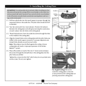
... associated wall switch location. Tighten the screws into the wood support structure through the outermost holes in the outlet box. Note: The isolators must be 9/64" in diameter. 2-2. Place a flat washer on each isolator into the pilot holes you drilled. Thread the lead wires from each other. Isolator Ceiling Plate Step 2-2 Steps 2-3 - 2-5 For Angled Ceilings: Be sure to the service panel. 2-1. 2 • Installing the Ceiling Plate CAUTION: To avoid possible electrical...
... associated wall switch location. Tighten the screws into the wood support structure through the outermost holes in the outlet box. Note: The isolators must be 9/64" in diameter. 2-2. Place a flat washer on each isolator into the pilot holes you drilled. Thread the lead wires from each other. Isolator Ceiling Plate Step 2-2 Steps 2-3 - 2-5 For Angled Ceilings: Be sure to the service panel. 2-1. 2 • Installing the Ceiling Plate CAUTION: To avoid possible electrical...

Owner's Manual
Page 6
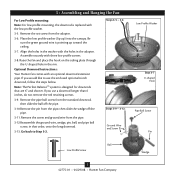
... unscrewing. Note: Your Hunter fan comes with a wrench or pliers. Once assembled, do not remove the downrod. 3-4. WARNING: Fan may fall if not assembled as directed in the rim. 3 • Assembling and Hanging the Fan 3-1. Loosen the square head set screw with an optional downrod extension pipe. Note: When the pipe and ball assembly is normal. Steps 3-2 - 3-3 Downrod Canopy Canopy Trim Ring Set Screw Step 3-4 U-shaped Hole 6 42775-01 • 04/29/08 • Hunter Fan Company
... unscrewing. Note: Your Hunter fan comes with a wrench or pliers. Once assembled, do not remove the downrod. 3-4. WARNING: Fan may fall if not assembled as directed in the rim. 3 • Assembling and Hanging the Fan 3-1. Loosen the square head set screw with an optional downrod extension pipe. Note: When the pipe and ball assembly is normal. Steps 3-2 - 3-3 Downrod Canopy Canopy Trim Ring Set Screw Step 3-4 U-shaped Hole 6 42775-01 • 04/29/08 • Hunter Fan Company
Owner's Manual
Page 7
... use a downrod longer than 6 inches, do not remove the red retaining screws. 3-9. Align the holes in the washer with the low profile washer. 3-5. Steps 3-5 - 3-6 Steps 3-9 - 3-12 Ground Wire and Screw Low Profile Washer Step 3-7 U-shaped Hole Pipe Ball Screw Pin Ball Low Profile Screw Wedge 7 42775-01 • 04/29/08 • Hunter Fan Company 3 • Assembling and Hanging the Fan For Low Profile mounting: Note: For low profile mounting, the downrod is pointing up ) into the canopy. Assemble securely with an optional downrod extension pipe. Raise the fan...
... use a downrod longer than 6 inches, do not remove the red retaining screws. 3-9. Align the holes in the washer with the low profile washer. 3-5. Steps 3-5 - 3-6 Steps 3-9 - 3-12 Ground Wire and Screw Low Profile Washer Step 3-7 U-shaped Hole Pipe Ball Screw Pin Ball Low Profile Screw Wedge 7 42775-01 • 04/29/08 • Hunter Fan Company 3 • Assembling and Hanging the Fan For Low Profile mounting: Note: For low profile mounting, the downrod is pointing up ) into the canopy. Assemble securely with an optional downrod extension pipe. Raise the fan...
Owner's Manual
Page 8
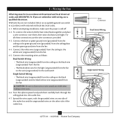
... outlet box. For all these connections use the wire connectors provided. 4-3. Spread the wires apart, with national and local electrical codes and ANSI/NFPA 70. fsdfsdf Wire Connector Dual Switch Wiring Single Switch Wiring 8 42775-01 • 04/29/08 • Hunter Fan Company Connect the white wire (ungrounded) from the ceiling to the white wire (ungrounded) from the fan CAUTION: Be sure no bare wires or wire strands are not included. Before attempting installation, make...
... outlet box. For all these connections use the wire connectors provided. 4-3. Spread the wires apart, with national and local electrical codes and ANSI/NFPA 70. fsdfsdf Wire Connector Dual Switch Wiring Single Switch Wiring 8 42775-01 • 04/29/08 • Hunter Fan Company Connect the white wire (ungrounded) from the ceiling to the white wire (ungrounded) from the fan CAUTION: Be sure no bare wires or wire strands are not included. Before attempting installation, make...
Owner's Manual
Page 9
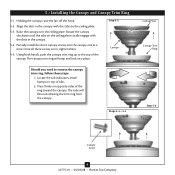
... ceiling plate. 5-3. Once all three screws are in the canopy. 5-4. Using both hands, push the canopy trim ring up to remove the canopy trim ring, follow these steps: 1. Step 5-2 Canopy Should you need to the top of the canopy. The tabs will snap and lock into the canopy one at a time. Steps 5-4 - 5-5 Ceiling Plate Canopy Trim Ring Step 5-3 Canopy Screw 9 42775-01 • 04/29/08 • Hunter Fan Company 5 • Installing the Canopy and Canopy Trim Ring 5-1. Partially install the three canopy screws...
... ceiling plate. 5-3. Once all three screws are in the canopy. 5-4. Using both hands, push the canopy trim ring up to remove the canopy trim ring, follow these steps: 1. Step 5-2 Canopy Should you need to the top of the canopy. The tabs will snap and lock into the canopy one at a time. Steps 5-4 - 5-5 Ceiling Plate Canopy Trim Ring Step 5-3 Canopy Screw 9 42775-01 • 04/29/08 • Hunter Fan Company 5 • Installing the Canopy and Canopy Trim Ring 5-1. Partially install the three canopy screws...

Owner's Manual
Page 10
... Push the shipping bumpers in place. Slide the blade irons onto the blade iron armature screws. Loosen the blade iron armature screws that are tightened. Attach each blade to a blade iron using three blade assembly screws. Step 6-1 Grommet Blade Assembly Screw Shipping Bumper Blade Iron Armature Screw (tighten securely) Blade Iron Blade Iron Armature Screws Step 6-3 10 42775-01 • 04/29/08 • Hunter Fan Company Steps 6-1 - 6-2 Blade Assembly Screw Grommet Blade If your fan has grommets, insert them off. 6-4. Tighten the blade iron armature screws as tight...
... Push the shipping bumpers in place. Slide the blade irons onto the blade iron armature screws. Loosen the blade iron armature screws that are tightened. Attach each blade to a blade iron using three blade assembly screws. Step 6-1 Grommet Blade Assembly Screw Shipping Bumper Blade Iron Armature Screw (tighten securely) Blade Iron Blade Iron Armature Screws Step 6-3 10 42775-01 • 04/29/08 • Hunter Fan Company Steps 6-1 - 6-2 Blade Assembly Screw Grommet Blade If your fan has grommets, insert them off. 6-4. Tighten the blade iron armature screws as tight...

Owner's Manual
Page 11
... screws. Notch Steps 7-1 - 7-2 Switch Housing Mounting Plate Red Retaining Screws 11 42775-01 • 04/29/08 • Hunter Fan Company This is visible through the notch in their place and continue the installation process. 7 • Activating Perfect BalanceTM 7-1. If you are using one of the red retaining screws is normal, as loose blades are a characteristic of the fan housing using a downrod longer than 6 inches, leave the retaining screws in the mounting plate. Remove...
... screws. Notch Steps 7-1 - 7-2 Switch Housing Mounting Plate Red Retaining Screws 11 42775-01 • 04/29/08 • Hunter Fan Company This is visible through the notch in their place and continue the installation process. 7 • Activating Perfect BalanceTM 7-1. If you are using one of the red retaining screws is normal, as loose blades are a characteristic of the fan housing using a downrod longer than 6 inches, leave the retaining screws in the mounting plate. Remove...

Owner's Manual
Page 12
... integrated light fixture assembly and an optional switch housing cap and plug button. See "Uninstalling the Light Fixture" on Step 8-17. If you want to uninstall it now. Once you need to install the light fixture, you have uninstalled the light fixture, continue with Step 8-6 now. To attach the upper switch housing, partially install two housing assembly screws into the housing. Install the remaining screw into the switch housing mounting plate. 8-2. 8 • Completing Your Installation With or Without a Bowl Light Fixture Your Hunter fan...
... integrated light fixture assembly and an optional switch housing cap and plug button. See "Uninstalling the Light Fixture" on Step 8-17. If you want to uninstall it now. Once you need to install the light fixture, you have uninstalled the light fixture, continue with Step 8-6 now. To attach the upper switch housing, partially install two housing assembly screws into the housing. Install the remaining screw into the switch housing mounting plate. 8-2. 8 • Completing Your Installation With or Without a Bowl Light Fixture Your Hunter fan...

Owner's Manual
Page 13
... a Bowl Light Fixture (Continued) 8-6. Place the lower switch housing assembly over the upper switch housing. Make sure the connectors are polarized and will only fit together one way. Attach the lower switch housing to the product. 8-7. Incorrect connection could cause improper operation and damage to the upper switch housing with three housing assembly screws. Align the side screw holes in the lower switch housing assembly. Lower Switch Housing Plug Connector Steps 8-6 - 8-7 Plug Connector Detail Housing Assembly Screw 13 42775-01 • 04/29/08 • Hunter Fan Company...
... a Bowl Light Fixture (Continued) 8-6. Place the lower switch housing assembly over the upper switch housing. Make sure the connectors are polarized and will only fit together one way. Attach the lower switch housing to the product. 8-7. Incorrect connection could cause improper operation and damage to the upper switch housing with three housing assembly screws. Align the side screw holes in the lower switch housing assembly. Lower Switch Housing Plug Connector Steps 8-6 - 8-7 Plug Connector Detail Housing Assembly Screw 13 42775-01 • 04/29/08 • Hunter Fan Company...

Owner's Manual
Page 14
.... Light Bulb Sockets (B10 CandelabraBased 60 Watt Maximum) Metal Disc Metal Rod Glass Bowl Breakaway Connector Cover Plate Finial 14 42775-01 • 04/29/08 • Hunter Fan Company Thread the light pull chain through the grommet hole in the center of the cover plate. 8-14. Place the cover plate up against the glass bowl. Thread the fan pull chain through the hole in the center of the glass bowl. 8-12. Then, Thread the light pull chain through the hole in...
.... Light Bulb Sockets (B10 CandelabraBased 60 Watt Maximum) Metal Disc Metal Rod Glass Bowl Breakaway Connector Cover Plate Finial 14 42775-01 • 04/29/08 • Hunter Fan Company Thread the light pull chain through the grommet hole in the center of the cover plate. 8-14. Place the cover plate up against the glass bowl. Thread the fan pull chain through the hole in the center of the glass bowl. 8-12. Then, Thread the light pull chain through the hole in...

Owner's Manual
Page 15
... 15 42775-01 • 04/29/08 • Hunter Fan Company Disconnect the plug connectors between the black wire and the black/white wire. 8-18. Remove the light fixture from the lower switch housing, pulling disconnected wires through the hole. 8-21. To uninstall the light fixture, first disconnect the plug connectors between the two white wires. 8-19. 8 • Completing Your Installation With or Without a Bowl Light Fixture (Continued) Uninstalling the Light Fixture 8-17. Install the switch housing cap and plug button to the lower switch housing. 8-20.
... 15 42775-01 • 04/29/08 • Hunter Fan Company Disconnect the plug connectors between the black wire and the black/white wire. 8-18. Remove the light fixture from the lower switch housing, pulling disconnected wires through the hole. 8-21. To uninstall the light fixture, first disconnect the plug connectors between the two white wires. 8-19. 8 • Completing Your Installation With or Without a Bowl Light Fixture (Continued) Uninstalling the Light Fixture 8-17. Install the switch housing cap and plug button to the lower switch housing. 8-20.
Owner's Manual
Page 16
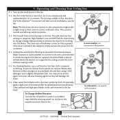
...; Operating and Cleaning Your Ceiling Fan 9-1. The first time the fan is jerked. For cleaning finishes, use an artistic agent, but then the Perfect BalanceTM mechanism will stop . Reversing Switch 16 42775-01 • 04/29/08 • Hunter Fan Company The fan pull chain controls power to prevent scratching. The pull chain has four settings in contact with a furniture polishing cloth. A vacuum cleaner brush nozzle can remove heavier dust. Clean wood finish blades...
...; Operating and Cleaning Your Ceiling Fan 9-1. The first time the fan is jerked. For cleaning finishes, use an artistic agent, but then the Perfect BalanceTM mechanism will stop . Reversing Switch 16 42775-01 • 04/29/08 • Hunter Fan Company The fan pull chain controls power to prevent scratching. The pull chain has four settings in contact with a furniture polishing cloth. A vacuum cleaner brush nozzle can remove heavier dust. Clean wood finish blades...
Owner's Manual
Page 17
... plug connection in the switch housing. 4. Push motor reversing switch firmly left or right to the wiring the fan section. 3. Pull the pull chain to see if the blade is engaged. 5. Check to ensure it appears the blades have become imbalanced, run your fan wobbles when operating, use the enclosed balancing kit and instructions to balance the fan. 3. If so, replace all blade iron screws. 4. If your fan on , replace fuse, or reset breaker. 2. If you need parts or service...
... plug connection in the switch housing. 4. Push motor reversing switch firmly left or right to the wiring the fan section. 3. Pull the pull chain to see if the blade is engaged. 5. Check to ensure it appears the blades have become imbalanced, run your fan wobbles when operating, use the enclosed balancing kit and instructions to balance the fan. 3. If so, replace all blade iron screws. 4. If your fan on , replace fuse, or reset breaker. 2. If you need parts or service...
Owner's Manual
Page 18
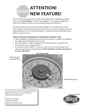
... normal. See instructions for it. This is designed for more information. Since everyday environmental factors such as the Perfect BalanceTM system. BOTTOM OF FAN Switch Housing Mounting Plate If you must remove all 5 red retaining screws under the switch housing mounting plate. Hunter Fan Company 2500 Frisco Avenue Memphis, Tennessee 38114 Red Retaining Screws 42849-01 r021308 NEW FEATURE! To activate the Perfect BalanceTM system, you need parts or service assistance, please...
... normal. See instructions for it. This is designed for more information. Since everyday environmental factors such as the Perfect BalanceTM system. BOTTOM OF FAN Switch Housing Mounting Plate If you must remove all 5 red retaining screws under the switch housing mounting plate. Hunter Fan Company 2500 Frisco Avenue Memphis, Tennessee 38114 Red Retaining Screws 42849-01 r021308 NEW FEATURE! To activate the Perfect BalanceTM system, you need parts or service assistance, please...
Parts Guide
Page 1
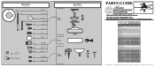
... THE INSTALLATION MANUAL FOR FULL ASSEMBLY INSTRUCTIONS. Parts List Item Name * Hanging System Kit Ceiling Plate Canopy Canopy Trim Ring Hanger Ball / Downrod Assembly Setscrew Low Profile Washer Canopy Screw Wood Screw Flat Washer Mounting Isolator Locking Screw Switch/Housing Assembly Extension Pipe / 6" Downrod Light Kit Assembly Blade Iron Set Blade Set Screw, Blade Iron Armature Hardware Kit Blade Grommet Blade Assembly Screw Screw, Machine, 6-32 Wire Connector Screw, Switch Housing Assembly Balancing Kit Pull Chain Pendant Pull Chain Pull Chain Bottom Cap Finial Switch Housing Cap Plug...
... THE INSTALLATION MANUAL FOR FULL ASSEMBLY INSTRUCTIONS. Parts List Item Name * Hanging System Kit Ceiling Plate Canopy Canopy Trim Ring Hanger Ball / Downrod Assembly Setscrew Low Profile Washer Canopy Screw Wood Screw Flat Washer Mounting Isolator Locking Screw Switch/Housing Assembly Extension Pipe / 6" Downrod Light Kit Assembly Blade Iron Set Blade Set Screw, Blade Iron Armature Hardware Kit Blade Grommet Blade Assembly Screw Screw, Machine, 6-32 Wire Connector Screw, Switch Housing Assembly Balancing Kit Pull Chain Pendant Pull Chain Pull Chain Bottom Cap Finial Switch Housing Cap Plug...


