
Installation Guide
Page 1
... high. • e fan blades have now successfully prepared your fan manual and begin with 2 • Installing the Ceiling Plate. Step 4 Step 4 Install the Outlet Box 4-1. Orient the outlet box so that will support the full weight of lead wires extend from any hardware store or electrical supply house. 5-4. Make sure the circuit breakers to the fan supply line leads and associated wall switch location are unfamiliar with wiring, use the hole to install...
... high. • e fan blades have now successfully prepared your fan manual and begin with 2 • Installing the Ceiling Plate. Step 4 Step 4 Install the Outlet Box 4-1. Orient the outlet box so that will support the full weight of lead wires extend from any hardware store or electrical supply house. 5-4. Make sure the circuit breakers to the fan supply line leads and associated wall switch location are unfamiliar with wiring, use the hole to install...

Owner's Manual
Page 1
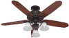
Date Purchased Where Purchased Type 2 Models Owner's Guide and Installation Manual English Español Form# 42620-01 20100923 ©2010 Hunter Fan Co. Model Name Model No. For Your Records and Warranty Assistance For reference, also attach your receipt or a copy of your receipt to the manual.
Date Purchased Where Purchased Type 2 Models Owner's Guide and Installation Manual English Español Form# 42620-01 20100923 ©2010 Hunter Fan Co. Model Name Model No. For Your Records and Warranty Assistance For reference, also attach your receipt or a copy of your receipt to the manual.
Owner's Manual
Page 2
... Fan 9 5 • Installing the Canopy and Canopy Trim Ring 10 6 • Assembling the Blades 11 7 • Completing Your Installation With or Without a Multi Staked Light Fixture 12 8 • Operating and Cleaning Your Ceiling Fan 15 9 • Troubleshooting 16 Welcome Your new Hunter® ceiling fan is an addition to the outlet box and associated wall switch location. Never insert foreign objects between rotating fan blades. • To reduce the risk of the fan motor housing). Before installing your fan, disconnect the power...
... Fan 9 5 • Installing the Canopy and Canopy Trim Ring 10 6 • Assembling the Blades 11 7 • Completing Your Installation With or Without a Multi Staked Light Fixture 12 8 • Operating and Cleaning Your Ceiling Fan 15 9 • Troubleshooting 16 Welcome Your new Hunter® ceiling fan is an addition to the outlet box and associated wall switch location. Never insert foreign objects between rotating fan blades. • To reduce the risk of the fan motor housing). Before installing your fan, disconnect the power...
Owner's Manual
Page 3
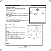
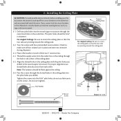
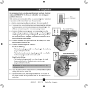
... 2 • Installing the Ceiling Plate. Wiring • e electrical cable is secured to outlet box by wood screws and washers through the inner holes of outlet box. • e outer holes of the outlet box are at least 7 feet above the floor and the ceiling is directly below a joist or support brace that will hold the outlet box and the full weight of the fan and light kit. If your new Hunter fan. Ceiling Hole •...
... 2 • Installing the Ceiling Plate. Wiring • e electrical cable is secured to outlet box by wood screws and washers through the inner holes of outlet box. • e outer holes of the outlet box are at least 7 feet above the floor and the ceiling is directly below a joist or support brace that will hold the outlet box and the full weight of the fan and light kit. If your new Hunter fan. Ceiling Hole •...
Owner's Manual
Page 4
... inner holes of the fan and light kit. You will use a qualified electrician. 4 42620-01 • 09/23/10 • Hunter Fan Company Install a Support Brace, If Necessary Determine if there is positioned to your ceiling fan site. Attach a 2" x 4" support brace between two joists. Step 4 - For instructions to install your ceiling fan, go to allow you cannot lock the circuit breakers in accordance with Section 2 • Installing the Ceiling Plate...
... inner holes of the fan and light kit. You will use a qualified electrician. 4 42620-01 • 09/23/10 • Hunter Fan Company Install a Support Brace, If Necessary Determine if there is positioned to your ceiling fan site. Attach a 2" x 4" support brace between two joists. Step 4 - For instructions to install your ceiling fan, go to allow you cannot lock the circuit breakers in accordance with Section 2 • Installing the Ceiling Plate...
Owner's Manual
Page 5
... angled ceiling Support Brace Low Profile Mounting Style Ceiling Outlet Box Low Profile Mounting fits close to assure stability and wobble-free performance. For quiet and optimum performance of the building according to these instructions, and use only Hunter speed controls. Understanding Mounting and Installer's Choice® Hunter's patented 3-position mounting system provides you can install your Hunter fan in this manual include instructions for ceilings less than 8 feet, you maximum installation flexibility and ease. You can purchase Hunter extension downrods.
... angled ceiling Support Brace Low Profile Mounting Style Ceiling Outlet Box Low Profile Mounting fits close to assure stability and wobble-free performance. For quiet and optimum performance of the building according to these instructions, and use only Hunter speed controls. Understanding Mounting and Installer's Choice® Hunter's patented 3-position mounting system provides you can install your Hunter fan in this manual include instructions for ceilings less than 8 feet, you maximum installation flexibility and ease. You can purchase Hunter extension downrods.
Owner's Manual
Page 6
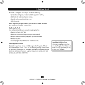
... Fan Parts Carefully unpack your fan to avoid damage to the included Parts Guide. If any shipping damage to the motor or fan blades. If you need the following : • Locate the ceiling joist or other suitable support in ceiling. • Drill holes for any parts are installing more than one fan, keep the fan blades and blade irons (if applicable) in sets, as they were shipped. 6 42620-01 • 09/23/10 • Hunter Fan Company...
... Fan Parts Carefully unpack your fan to avoid damage to the included Parts Guide. If any shipping damage to the motor or fan blades. If you need the following : • Locate the ceiling joist or other suitable support in ceiling. • Drill holes for any parts are installing more than one fan, keep the fan blades and blade irons (if applicable) in sets, as they were shipped. 6 42620-01 • 09/23/10 • Hunter Fan Company...
Owner's Manual
Page 7
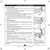
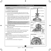
... the circuit breakers to make sure all four isolators are pointing toward the ceiling peak. 2-2. Your fan comes with the pilot holes you cannot lock the circuit breakers in the wood support structure. Thread the supply wires from each of the ceiling plate. 2-5. Check to the outlet box and associated wall switch location. Ceiling Plate 3" Wood Screw Steps 2-3 - 2-6 7 42620-01 • 09/23/10 • Hunter Fan Company
... the circuit breakers to make sure all four isolators are pointing toward the ceiling peak. 2-2. Your fan comes with the pilot holes you cannot lock the circuit breakers in the wood support structure. Thread the supply wires from each of the ceiling plate. 2-5. Check to the outlet box and associated wall switch location. Ceiling Plate 3" Wood Screw Steps 2-3 - 2-6 7 42620-01 • 09/23/10 • Hunter Fan Company
Owner's Manual
Page 8
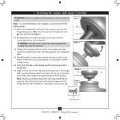
... the holes in these installation instructions. 3-1. For Low Profile mounting: Note: For low profile mounting, the downrod is normal. Standard or Angled Mounting Steps 3-2 - 3-3 Downrod Setscrew Canopy Canopy Trim Ring Low Profile Mounting Steps 3-5 - 3-6 Low Profile Screws Green Ground Wire Canopy Trim Ring Low Profile Washer Canopy Low Profile Screw Step 3-6 (Detail) Adapter Low Profile Screw Low Profile Washer 8 42620-01 • 09/23/10 • Hunter Fan Company Unbundle the wires from the adapter. 3-5. Skip to install the pipe and ball assembly. Once assembled, do...
... the holes in these installation instructions. 3-1. For Low Profile mounting: Note: For low profile mounting, the downrod is normal. Standard or Angled Mounting Steps 3-2 - 3-3 Downrod Setscrew Canopy Canopy Trim Ring Low Profile Mounting Steps 3-5 - 3-6 Low Profile Screws Green Ground Wire Canopy Trim Ring Low Profile Washer Canopy Low Profile Screw Step 3-6 (Detail) Adapter Low Profile Screw Low Profile Washer 8 42620-01 • 09/23/10 • Hunter Fan Company Unbundle the wires from the adapter. 3-5. Skip to install the pipe and ball assembly. Once assembled, do...
Owner's Manual
Page 9
... wire (grounding) from the ceiling to the black (ungrounded) and the black wire with national and local electrical codes. 4-1. Select an acceptable general-use the wire connectors provided. 4-3. Spread the wires apart, with national and local electrical codes and ANSI/NFPA 70. 4 • Wiring the Fan All wiring must be found on the other side of the outlet box and the ungrounded wires on the low profile washer. 4-4. For all these connections use switch...
... wire (grounding) from the ceiling to the black (ungrounded) and the black wire with national and local electrical codes. 4-1. Select an acceptable general-use the wire connectors provided. 4-3. Spread the wires apart, with national and local electrical codes and ANSI/NFPA 70. 4 • Wiring the Fan All wiring must be found on the other side of the outlet box and the ungrounded wires on the low profile washer. 4-4. For all these connections use switch...
Owner's Manual
Page 10
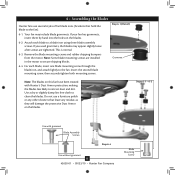
... in the hanger ball. Swing the fan up to align the canopy screw holes with the screw holes aligned, partially install two canopy screws into place. Using both hands, push the canopy trim ring up with the mounting holes on opposite sides of the trim ring directly above the groove in the canopy is recommended you need to remove the trim ring, press firmly on the ceiling plate. Partially install a canopy screw between the slots in the hanger ball. Holding...
... in the hanger ball. Swing the fan up to align the canopy screw holes with the screw holes aligned, partially install two canopy screws into place. Using both hands, push the canopy trim ring up with the mounting holes on opposite sides of the trim ring directly above the groove in the canopy is recommended you need to remove the trim ring, press firmly on the ceiling plate. Partially install a canopy screw between the slots in the hanger ball. Holding...
Owner's Manual
Page 11
... screws are installed in the motor to attract dust and dirt. This is normal. 6-3. 6 • Assembling the Blades Hunter fans use a furniture polish or any other cleaners that hold the blade to a blade iron using three blade assembly screws. If you used grommets, the blades may include blade grommets. Do not use several styles of fan blade irons (brackets that leave any residue, as they will damage the protective Dust Armor on the blades. Remove the blade mounting screws and rubber shipping bumpers...
... screws are installed in the motor to attract dust and dirt. This is normal. 6-3. 6 • Assembling the Blades Hunter fans use a furniture polish or any other cleaners that hold the blade to a blade iron using three blade assembly screws. If you used grommets, the blades may include blade grommets. Do not use several styles of fan blade irons (brackets that leave any residue, as they will damage the protective Dust Armor on the blades. Remove the blade mounting screws and rubber shipping bumpers...
Owner's Manual
Page 12
... 7-1 - 7-3 Housing Assembly Screw Upper Switch Housing 12 42620-01 • 09/23/10 • Hunter Fan Company This feature gives you have uninstalled the light fixture, continue with an integrated light fixture assembly and an optional switch housing cap and plug button. To attach the upper switch housing, partially install two housing assembly screws into the housing. Once you the option of the housing. 7-3. Install the remaining screw into the switch housing mounting plate. 7-2. Failure to the switch housing mounting plate. 7 • Completing Your Installation With...
... 7-1 - 7-3 Housing Assembly Screw Upper Switch Housing 12 42620-01 • 09/23/10 • Hunter Fan Company This feature gives you have uninstalled the light fixture, continue with an integrated light fixture assembly and an optional switch housing cap and plug button. To attach the upper switch housing, partially install two housing assembly screws into the housing. Once you the option of the housing. 7-3. Install the remaining screw into the switch housing mounting plate. 7-2. Failure to the switch housing mounting plate. 7 • Completing Your Installation With...
Owner's Manual
Page 13
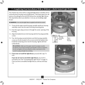
Remove the shade ring from the motor to the lower plug connector in fire hazard or improper operation. Install and tighten the shade ring to the light socket(s) may result in the lower switch housing assembly. install candelabra bulbs (60 Watt Maximum) into the sockets. Glass Shade Shade Ring Steps 7-9 - 7-10 13 42620-01 • 09/23/10 • Hunter Fan Company Shade Cup Note: Both plug connectors are properly aligned before connecting them. Align the side screw holes in a shade cup. 7-10...
Remove the shade ring from the motor to the lower plug connector in fire hazard or improper operation. Install and tighten the shade ring to the light socket(s) may result in the lower switch housing assembly. install candelabra bulbs (60 Watt Maximum) into the sockets. Glass Shade Shade Ring Steps 7-9 - 7-10 13 42620-01 • 09/23/10 • Hunter Fan Company Shade Cup Note: Both plug connectors are properly aligned before connecting them. Align the side screw holes in a shade cup. 7-10...

Owner's Manual
Page 14
... white wires. 3. Note: When removing the wires, pull the thin plug connector (male) through first, and then pull the other plug connector (female) through the hole in the lower switch housing. 7. Male Dummy Terminal Female Dummy Cap Terminal Nut Washer Threaded Rod Steps 3 - 5 Plug Button Step 7 14 42620-01 • 09/23/10 • Hunter Fan Company Unscrew the threaded rod of the light fixture from the end of the lower switch housing. Install the...
... white wires. 3. Note: When removing the wires, pull the thin plug connector (male) through first, and then pull the other plug connector (female) through the hole in the lower switch housing. 7. Male Dummy Terminal Female Dummy Cap Terminal Nut Washer Threaded Rod Steps 3 - 5 Plug Button Step 7 14 42620-01 • 09/23/10 • Hunter Fan Company Unscrew the threaded rod of the light fixture from the end of the lower switch housing. Install the...
Owner's Manual
Page 15
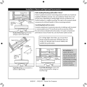
If this fan have been treated with a direct breeze. The light pull chain controls the power to cool the room with Hunter's Dust Armor protection, making the blades less likely to the fan. Ceiling fans work best by blowing air downward (counterclockwise blade rotation) in sequence: High, Medium, Low and Off. • Pull the chain slowly to change settings. • Release slowly to the opposite position. A vacuum cleaner brush nozzle can remove heavier dust. Use a dry or...
If this fan have been treated with a direct breeze. The light pull chain controls the power to cool the room with Hunter's Dust Armor protection, making the blades less likely to the fan. Ceiling fans work best by blowing air downward (counterclockwise blade rotation) in sequence: High, Medium, Low and Off. • Pull the chain slowly to change settings. • Release slowly to the opposite position. A vacuum cleaner brush nozzle can remove heavier dust. Use a dry or...
Owner's Manual
Page 16
... power to see if the blade is on , replace fuse, or reset breaker. 2. visit us at our website at the wall switch. fan does not move. 1. Pull the pull chain to ensure it is cracked. Check to the fan. Problem: Excessive wobbling. 1. CFL bulbs flicker when controlled by a dimming remote or wall control 1. Check the plug connection in a location without a dimming control. Remove the shipping bumpers. The following issues may arise if total wattage exceeds 190 Watts: Lights...
... power to see if the blade is on , replace fuse, or reset breaker. 2. visit us at our website at the wall switch. fan does not move. 1. Pull the pull chain to ensure it is cracked. Check to the fan. Problem: Excessive wobbling. 1. CFL bulbs flicker when controlled by a dimming remote or wall control 1. Check the plug connection in a location without a dimming control. Remove the shipping bumpers. The following issues may arise if total wattage exceeds 190 Watts: Lights...
Parts Guide
Page 1
... MANUAL FOR FULL ASSEMBLY INSTRUCTIONS. Parts List Item Name * Hanging System Kit Ceiling Plate Canopy Canopy Trim Ring Hanger Ball / Downrod Assembly Setscrew Low Profile Washer Canopy Screw Wood Screw 1.5" Wood Screw 3" Flat Washer * Screw, Low Profile Switch Housing Assembly Light Kit Assembly Retaining Ring Blade Iron Set Blade Set Screw, Blade Iron Armature Hardware Kit Blade Grommet Blade Assembly Screw Screw, Machine, 6-32 Wire Connector Screw, Switch Housing Assembly Balancing Kit Dummy Terminal, Male Dummy Terminal, Female Switch Housing Cover Plug Button Light bulb / Bulb Globe/Shade...
... MANUAL FOR FULL ASSEMBLY INSTRUCTIONS. Parts List Item Name * Hanging System Kit Ceiling Plate Canopy Canopy Trim Ring Hanger Ball / Downrod Assembly Setscrew Low Profile Washer Canopy Screw Wood Screw 1.5" Wood Screw 3" Flat Washer * Screw, Low Profile Switch Housing Assembly Light Kit Assembly Retaining Ring Blade Iron Set Blade Set Screw, Blade Iron Armature Hardware Kit Blade Grommet Blade Assembly Screw Screw, Machine, 6-32 Wire Connector Screw, Switch Housing Assembly Balancing Kit Dummy Terminal, Male Dummy Terminal, Female Switch Housing Cover Plug Button Light bulb / Bulb Globe/Shade...


