
Installation Guide
Page 1
... box a minimum of outlet box. o e outer holes of the fan and light kit. Tools and Supplies You May Need • Drill • Keyhole saw • 2' x 4' support brace • UL-approved octagonal 4" x 1-1/2" outlet box • Two #8 x 1-1/2" wood screws and washers • Approved connector for electrical wire Checklist for safety, reliable operation, maximum efficiency, and energy savings. Fan Support System Fan Support System Suitable Existing Fan Site Wiring Outlet Box Hunter Fan Company Step 2 Cut the Ceiling Hole...
... box a minimum of outlet box. o e outer holes of the fan and light kit. Tools and Supplies You May Need • Drill • Keyhole saw • 2' x 4' support brace • UL-approved octagonal 4" x 1-1/2" outlet box • Two #8 x 1-1/2" wood screws and washers • Approved connector for electrical wire Checklist for safety, reliable operation, maximum efficiency, and energy savings. Fan Support System Fan Support System Suitable Existing Fan Site Wiring Outlet Box Hunter Fan Company Step 2 Cut the Ceiling Hole...

Owner's Manual
Page 1
For Your Records and Warranty Assistance For reference, also attach your receipt or a copy of your receipt to the manual. Date Purchased Where Purchased Type T,G,B Models Owner's Guide and Installation Manual English Español Form# 41847-01 20100528 ©2010 Hunter Fan Co. Model Name Model No.
For Your Records and Warranty Assistance For reference, also attach your receipt or a copy of your receipt to the manual. Date Purchased Where Purchased Type T,G,B Models Owner's Guide and Installation Manual English Español Form# 41847-01 20100528 ©2010 Hunter Fan Co. Model Name Model No.
Owner's Manual
Page 2
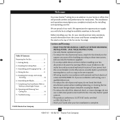
... Getting Ready 6 2 • Installing the Ceiling Plate 7 3 • Assembling and Hanging the Fan . . . . 8 4 • Wiring the Fan 9 5 • Installing the Canopy and Canopy Trim Ring 10 6 • Assembling the Blades 11 7 • Completing Your Installation With or Without a Bowl Light Fixture 12 8 • Operating and Cleaning Your Ceiling Fan 16 9 • Troubleshooting 17 Cautions and Warnings • READ THIS ENTIRE MANUAL CAREFULLY BEFORE BEGINNING INSTALLATION. Before installing your fan, for installing and operating your fan, disconnect the power by turning off...
... Getting Ready 6 2 • Installing the Ceiling Plate 7 3 • Assembling and Hanging the Fan . . . . 8 4 • Wiring the Fan 9 5 • Installing the Canopy and Canopy Trim Ring 10 6 • Assembling the Blades 11 7 • Completing Your Installation With or Without a Bowl Light Fixture 12 8 • Operating and Cleaning Your Ceiling Fan 16 9 • Troubleshooting 17 Cautions and Warnings • READ THIS ENTIRE MANUAL CAREFULLY BEFORE BEGINNING INSTALLATION. Before installing your fan, for installing and operating your fan, disconnect the power by turning off...

Owner's Manual
Page 3
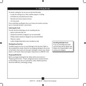
... are at least 7 feet above the floor and the ceiling is directly below the joist or support brace. Wiring • e electrical cable is recessed a minimum of the outlet box is secured to Section 2 • Installing the Ceiling Plate. If your new Hunter fan. Fan Support System Fan Support System Suitable Existing Fan Site Wiring Outlet Box 3 41847-01 • 05/28/10 • Hunter Fan Company Choose a fan site where: • No object...
... are at least 7 feet above the floor and the ceiling is directly below the joist or support brace. Wiring • e electrical cable is recessed a minimum of the outlet box is secured to Section 2 • Installing the Ceiling Plate. If your new Hunter fan. Fan Support System Fan Support System Suitable Existing Fan Site Wiring Outlet Box 3 41847-01 • 05/28/10 • Hunter Fan Company Choose a fan site where: • No object...
Owner's Manual
Page 4
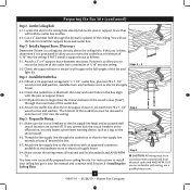
.../10 • Hunter Fan Company Prepare the Wiring 5-1. For instructions to install your ceiling fan, go to recess the bottom of the outlet box a minimum of the fan and light kit. You will support the full weight of 1/16" into the ceiling. Step 3 - Obtain a UL-approved octagonal 4" x 1-1/2" outlet box, plus two #8 x 1-1/2" wood screws and washers, available from any hardware store or electrical supply house. 5-4. Make certain the wiring meets all national...
.../10 • Hunter Fan Company Prepare the Wiring 5-1. For instructions to install your ceiling fan, go to recess the bottom of the outlet box a minimum of the fan and light kit. You will support the full weight of 1/16" into the ceiling. Step 3 - Obtain a UL-approved octagonal 4" x 1-1/2" outlet box, plus two #8 x 1-1/2" wood screws and washers, available from any hardware store or electrical supply house. 5-4. Make certain the wiring meets all national...
Owner's Manual
Page 5
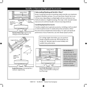
...purchase Hunter extension downrods. Considering Optional Accessories Consider using Hunter's optional accessories, including a wall-mounted or remote speed control. All Hunter fans use sturdy 3/4" diameter pipe to these instructions, and use the accessories, follow the instructions included with each product. The steps in one of your Hunter fan in this manual include instructions for ceilings less than 8 feet, you maximum installation flexibility and ease. Angled Mounting Style 8 12 Angled Mounting recommended for a vaulted or angled ceiling Support Brace Low Profile Mounting...
...purchase Hunter extension downrods. Considering Optional Accessories Consider using Hunter's optional accessories, including a wall-mounted or remote speed control. All Hunter fans use sturdy 3/4" diameter pipe to these instructions, and use the accessories, follow the instructions included with each product. The steps in one of your Hunter fan in this manual include instructions for ceilings less than 8 feet, you maximum installation flexibility and ease. Angled Mounting Style 8 12 Angled Mounting recommended for a vaulted or angled ceiling Support Brace Low Profile Mounting...
Owner's Manual
Page 6
... blade irons (if applicable) in sets, as they were shipped. 6 41847-01 • 05/28/10 • Hunter Fan Company Preparing the Fan Site Before you are essential for safety, reliable operation, maximum efficiency, and energy savings. Proper ceiling fan location and attachment to the motor or fan blades. If you begin installing the fan, follow all the instructions in ceiling. • Drill holes for and install wood screws. • Identify and connect electrical wires...
... blade irons (if applicable) in sets, as they were shipped. 6 41847-01 • 05/28/10 • Hunter Fan Company Preparing the Fan Site Before you are essential for safety, reliable operation, maximum efficiency, and energy savings. Proper ceiling fan location and attachment to the motor or fan blades. If you begin installing the fan, follow all the instructions in ceiling. • Drill holes for and install wood screws. • Identify and connect electrical wires...
Owner's Manual
Page 7
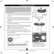
... breakers to the outlet box and associated wall switch location. Tighten the screws into the holes in the ceiling plate with four neoprene noise isolators ("Isolators"). Position the isolators between the ceiling plate and ceiling by turning off position, securely fasten a prominent warning device, such as a tag, to the service panel. 2-1. Isolator Ceiling Plate Flat Washer Step 2-2 Steps 2-3 - 2-5 3" Wood Screw For Angled Ceilings: Be sure to orient the ceiling plate so that the arrows...
... breakers to the outlet box and associated wall switch location. Tighten the screws into the holes in the ceiling plate with four neoprene noise isolators ("Isolators"). Position the isolators between the ceiling plate and ceiling by turning off position, securely fasten a prominent warning device, such as a tag, to the service panel. 2-1. Isolator Ceiling Plate Flat Washer Step 2-2 Steps 2-3 - 2-5 3" Wood Screw For Angled Ceilings: Be sure to orient the ceiling plate so that the arrows...
Owner's Manual
Page 8
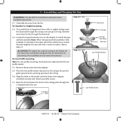
... the adapter to Step 3-7. Unbundle the wires from a flat or angled ceiling, insert the downrod through the downrod. 3-3. Loosen the square head setscrew on the ceiling plate through the U-shaped hole in the adapter. Securely retighten the setscrew with the holes in the rim. Align the holes in these installation instructions. 3-1. Step 3-7 U-shaped Hole Steps 3-2 - 3-3 Downrod Canopy Canopy Trim Ring Setscrew Steps 3-5 - 3-6 Low Profile Washer Low Profile Screw 8 41847-01 • 05/28/10 • Hunter Fan Company
... the adapter to Step 3-7. Unbundle the wires from a flat or angled ceiling, insert the downrod through the downrod. 3-3. Loosen the square head setscrew on the ceiling plate through the U-shaped hole in the adapter. Securely retighten the setscrew with the holes in the rim. Align the holes in these installation instructions. 3-1. Step 3-7 U-shaped Hole Steps 3-2 - 3-3 Downrod Canopy Canopy Trim Ring Setscrew Steps 3-5 - 3-6 Low Profile Washer Low Profile Screw 8 41847-01 • 05/28/10 • Hunter Fan Company
Owner's Manual
Page 9
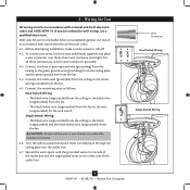
.... Wire Connector Dual Switch Wiring Single Switch Wiring 9 41847-01 • 05/28/10 • Hunter Fan Company For all these connections use a qualified electrician. Select an acceptable general-use switch in accordance with national and local electrical codes and ANSI/NFPA 70. Spread the wires apart, with wiring, use the wire connectors provided. 4-3. Connect the remaining wires as follows: Dual Switch Wiring: • The black wire (ungrounded) from the ceiling to the black wire (ungrounded) from the fan • The black/white wire...
.... Wire Connector Dual Switch Wiring Single Switch Wiring 9 41847-01 • 05/28/10 • Hunter Fan Company For all these connections use a qualified electrician. Select an acceptable general-use switch in accordance with national and local electrical codes and ANSI/NFPA 70. Spread the wires apart, with wiring, use the wire connectors provided. 4-3. Connect the remaining wires as follows: Dual Switch Wiring: • The black wire (ungrounded) from the ceiling to the black wire (ungrounded) from the fan • The black/white wire...
Owner's Manual
Page 10
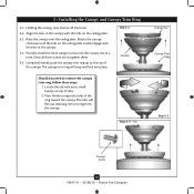
... Canopy Trim Ring 5-1. Partially install the three canopy screws into place. Steps 5-4 - 5-5 Ceiling Plate Canopy Trim Ring Step 5-3 Canopy Screw 10 41847-01 • 05/28/10 • Hunter Fan Company The tabs will snap and lock into the canopy one at a time. Holding the canopy, raise the fan off the hook. 5-2. Once all three screws are in the canopy. 5-4. Raise the canopy over the ceiling plate. Using both hands, push the canopy trim ring up to remove the canopy trim ring...
... Canopy Trim Ring 5-1. Partially install the three canopy screws into place. Steps 5-4 - 5-5 Ceiling Plate Canopy Trim Ring Step 5-3 Canopy Screw 10 41847-01 • 05/28/10 • Hunter Fan Company The tabs will snap and lock into the canopy one at a time. Holding the canopy, raise the fan off the hook. 5-2. Once all three screws are in the canopy. 5-4. Raise the canopy over the ceiling plate. Using both hands, push the canopy trim ring up to remove the canopy trim ring...
Owner's Manual
Page 11
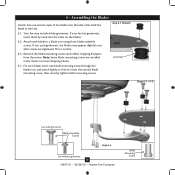
... iron, and attach lightly to secure shipping blocks. 6-4. This is normal. 6-3. For each blade to the fan). 6-1. If you used grommets, the blades may include blade grommets. Note: Some blade mounting screws are tightened. Step 6-1 (Detail) Grommet Steps 6-1 - 6-2 Use with grommet Blade Assembly Screws Step 6-4 Use without grommet 11 41847-01 • 05/28/10 • Hunter Fan Company Blade Mounting Screw Insert the second blade mounting screw, then securely tighten both mounting screws. Remove the blade mounting screws and rubber shipping bumpers from the motor...
... iron, and attach lightly to secure shipping blocks. 6-4. This is normal. 6-3. For each blade to the fan). 6-1. If you used grommets, the blades may include blade grommets. Note: Some blade mounting screws are tightened. Step 6-1 (Detail) Grommet Steps 6-1 - 6-2 Use with grommet Blade Assembly Screws Step 6-4 Use without grommet 11 41847-01 • 05/28/10 • Hunter Fan Company Blade Mounting Screw Insert the second blade mounting screw, then securely tighten both mounting screws. Remove the blade mounting screws and rubber shipping bumpers from the motor...

Owner's Manual
Page 12
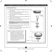
Tighten all three assembly screws could result in the housing with this fan model. 7-1. Failure to install the light fixture, proceed with step 7-6. Steps 7-1 - 7-3 Housing Assembly Screw Upper Switch Housing 12 41847-01 • 05/28/10 • Hunter Fan Company If you the option of installing the fan with an integrated light fixture assembly and an optional switch housing cap and plug button. The steps below direct you whether or not you are firmly situated in...
Tighten all three assembly screws could result in the housing with this fan model. 7-1. Failure to install the light fixture, proceed with step 7-6. Steps 7-1 - 7-3 Housing Assembly Screw Upper Switch Housing 12 41847-01 • 05/28/10 • Hunter Fan Company If you the option of installing the fan with an integrated light fixture assembly and an optional switch housing cap and plug button. The steps below direct you whether or not you are firmly situated in...

Owner's Manual
Page 13
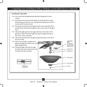
...; Hunter Fan Company Make sure the connectors are polarized and will only fit together one way. Attach the lower switch housing to the lower plug connector in the upper and lower switch housings. Incorrect connection could cause improper operation and damage to install the glass bowl. Align the side screw holes in the lower switch housing assembly. To attach the lower switch housing, connect the upper plug connector from the motor to the upper switch housing with step 7-8. 7-8. If you are not installing the light fixture, your installation...
...; Hunter Fan Company Make sure the connectors are polarized and will only fit together one way. Attach the lower switch housing to the lower plug connector in the upper and lower switch housings. Incorrect connection could cause improper operation and damage to install the glass bowl. Align the side screw holes in the lower switch housing assembly. To attach the lower switch housing, connect the upper plug connector from the motor to the upper switch housing with step 7-8. 7-8. If you are not installing the light fixture, your installation...
Owner's Manual
Page 14
... the wattage limit marked on the MAX wattage sticker affixed to be operating properly, see the troubleshooting section. Screw the threaded rod of the light fixture inside the lower switch housing. 7-13. CAUTION: Be sure no bare wires or wire strands are visible after making connections. Threaded Rod 7-14. Steps 7-17 - 7-19 Cap Plug Button Step 7-21 14 41847-01 • 05/28/10 • Hunter Fan Company Lower Switch Housing Note...
... the wattage limit marked on the MAX wattage sticker affixed to be operating properly, see the troubleshooting section. Screw the threaded rod of the light fixture inside the lower switch housing. 7-13. CAUTION: Be sure no bare wires or wire strands are visible after making connections. Threaded Rod 7-14. Steps 7-17 - 7-19 Cap Plug Button Step 7-21 14 41847-01 • 05/28/10 • Hunter Fan Company Lower Switch Housing Note...
Owner's Manual
Page 15
... Rod Metal Disk Breakaway Connector Glass Bowl Cover Plate Finial 15 41847-01 • 05/28/10 • Hunter Fan Company Align the holes in the center of the glass bowl. Thread the fan pull chain through the hole in the side of the extra chain.) 7-18. First install B10 candelabra bulbs (60 Watt Maximum) into the sockets. 7-17. Thread the light pull chain through the finial and screw the finial onto the threaded rod...
... Rod Metal Disk Breakaway Connector Glass Bowl Cover Plate Finial 15 41847-01 • 05/28/10 • Hunter Fan Company Align the holes in the center of the glass bowl. Thread the fan pull chain through the hole in the side of the extra chain.) 7-18. First install B10 candelabra bulbs (60 Watt Maximum) into the sockets. 7-17. Thread the light pull chain through the finial and screw the finial onto the threaded rod...
Owner's Manual
Page 16
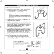
... four settings in warm weather to a complete stop. A vacuum cleaner brush nozzle can remove heavier dust. Reversing Switch 16 41847-01 • 05/28/10 • Hunter Fan Company 8 • Operating and Cleaning Your Ceiling Fan 8-1. The fan pull chain controls power to the light fixture. The light pull chain controls the power to the fan. Occasionally, apply a light coat of furniture polish for added protection and beauty. Restart fan. For cleaning finishes, use upward air flow pattern To Change Airflow Direction...
... four settings in warm weather to a complete stop. A vacuum cleaner brush nozzle can remove heavier dust. Reversing Switch 16 41847-01 • 05/28/10 • Hunter Fan Company 8 • Operating and Cleaning Your Ceiling Fan 8-1. The fan pull chain controls power to the light fixture. The light pull chain controls the power to the fan. Occasionally, apply a light coat of furniture polish for added protection and beauty. Restart fan. For cleaning finishes, use upward air flow pattern To Change Airflow Direction...
Owner's Manual
Page 17
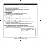
... the wall switch. Turn power on . 6. CFL light bulbs are installed meet the specifications on the MAX wattage sticker affixed to ensure that the switch is cracked. Pull the pull chain to the fan off suddenly, but fan is on , replace fuse, or reset breaker. 2. Turn the power to ensure it is still operating 1. Problem: Lights shut off at http://www.hunterfan.com. 9 • Troubleshooting Problem: Nothing happens; Problem: Noisy operation. 1. Tighten the blade assembly screws and blade iron armature screws until...
... the wall switch. Turn power on . 6. CFL light bulbs are installed meet the specifications on the MAX wattage sticker affixed to ensure that the switch is cracked. Pull the pull chain to the fan off suddenly, but fan is on , replace fuse, or reset breaker. 2. Turn the power to ensure it is still operating 1. Problem: Lights shut off at http://www.hunterfan.com. 9 • Troubleshooting Problem: Nothing happens; Problem: Noisy operation. 1. Tighten the blade assembly screws and blade iron armature screws until...
Parts Guide
Page 1
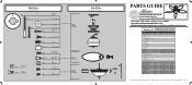
...THE INSTALLATION MANUAL FOR FULL ASSEMBLY INSTRUCTIONS. Parts List Item Name Hanging System Kit Ceiling Plate Canopy Canopy Trim Ring Hanger Ball / Downrod Assembly Low Profile Washer Wood Screw Flat Washer Mounting Isolator Screw, Low Profile Canopy Screw Setscrew Blade Iron Set Blade Set Hardware Kit Screw, Blade Iron Armature Blade Assembly Screw Blade Grommet Wire Connector Screw, Switch Housing Assembly Screw, Machine, 6-32 Switch Housing Assembly Light Kit Assembly Cap, Switch Housing Plug Button Pull Chain Pendant Pull Chain Extension Globe/Shade Light bulb / Bulb Balancing Kit Model...
...THE INSTALLATION MANUAL FOR FULL ASSEMBLY INSTRUCTIONS. Parts List Item Name Hanging System Kit Ceiling Plate Canopy Canopy Trim Ring Hanger Ball / Downrod Assembly Low Profile Washer Wood Screw Flat Washer Mounting Isolator Screw, Low Profile Canopy Screw Setscrew Blade Iron Set Blade Set Hardware Kit Screw, Blade Iron Armature Blade Assembly Screw Blade Grommet Wire Connector Screw, Switch Housing Assembly Screw, Machine, 6-32 Switch Housing Assembly Light Kit Assembly Cap, Switch Housing Plug Button Pull Chain Pendant Pull Chain Extension Globe/Shade Light bulb / Bulb Balancing Kit Model...


