
Installation Guide
Page 1
... rotating fan blades during normal operation. • e fan blades are at least 7 feet above the ceiling hole. Make sure the circuit breakers to building structure. Fan Support System o Fan attaches directly to the fan supply line leads and associated wall switch location are aligned with joist or support brace. o Fan support system will hold the outlet box and the full weight of the fan. Fan Support System Fan Support System Suitable Existing Fan Site Wiring Outlet Box Hunter Fan Company...
... rotating fan blades during normal operation. • e fan blades are at least 7 feet above the ceiling hole. Make sure the circuit breakers to building structure. Fan Support System o Fan attaches directly to the fan supply line leads and associated wall switch location are aligned with joist or support brace. o Fan support system will hold the outlet box and the full weight of the fan. Fan Support System Fan Support System Suitable Existing Fan Site Wiring Outlet Box Hunter Fan Company...

Owner's Manual
Page 1
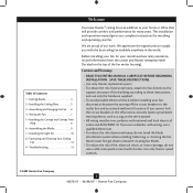
Date Purchased Where Purchased Type 2 Models Owner's Guide and Installation Manual English Español Form# 42678-01 20090608 ©2009 Hunter Fan Co. Model Name Model No. For Your Records and Warranty Assistance For reference, also attach your receipt or a copy of your receipt to the manual.
Date Purchased Where Purchased Type 2 Models Owner's Guide and Installation Manual English Español Form# 42678-01 20090608 ©2009 Hunter Fan Co. Model Name Model No. For Your Records and Warranty Assistance For reference, also attach your receipt or a copy of your receipt to the manual.
Owner's Manual
Page 2
...4 2 • Installing the Ceiling Plate 5 3 • Assembling and Hanging the Fan . . . . 6 4 • Wiring the Fan 7 5 • Installing the Canopy and Canopy Trim Ring 8 6 • Assembling the Blades 9 7 • Installing the Light Kit 10 8 • Operating and Cleaning Your Ceiling Fan 12 9 • Troubleshooting 13 Welcome Your new Hunter® ceiling fan is an addition to the service panel. • All wiring must be in accordance with national and local electrical codes and ANSI/NFPA 70. SAVE THESE INSTRUCTIONS. • Use only Hunter replacement parts. • To...
...4 2 • Installing the Ceiling Plate 5 3 • Assembling and Hanging the Fan . . . . 6 4 • Wiring the Fan 7 5 • Installing the Canopy and Canopy Trim Ring 8 6 • Assembling the Blades 9 7 • Installing the Light Kit 10 8 • Operating and Cleaning Your Ceiling Fan 12 9 • Troubleshooting 13 Welcome Your new Hunter® ceiling fan is an addition to the service panel. • All wiring must be in accordance with national and local electrical codes and ANSI/NFPA 70. SAVE THESE INSTRUCTIONS. • Use only Hunter replacement parts. • To...
Owner's Manual
Page 3
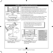
...to these instructions, and use only the hardware supplied. 3 42678-01 • 06/08/09 • Hunter Fan Company Installer's Choice and Optional Accessories Support Brace Standard Mounting Style Ceiling Outlet Box Standard Mounting hangs from the ceiling by a downrod (included). Considering Optional Accessories Consider using Hunter's optional accessories, including a wall-mounted or remote speed control. Angled Mounting Style 8 12 Angled Mounting recommended for a vaulted or angled ceiling Support Brace Low Profile Mounting Style Ceiling Outlet Box Low Profile Mounting fits close...
...to these instructions, and use only the hardware supplied. 3 42678-01 • 06/08/09 • Hunter Fan Company Installer's Choice and Optional Accessories Support Brace Standard Mounting Style Ceiling Outlet Box Standard Mounting hangs from the ceiling by a downrod (included). Considering Optional Accessories Consider using Hunter's optional accessories, including a wall-mounted or remote speed control. Angled Mounting Style 8 12 Angled Mounting recommended for a vaulted or angled ceiling Support Brace Low Profile Mounting Style Ceiling Outlet Box Low Profile Mounting fits close...
Owner's Manual
Page 4
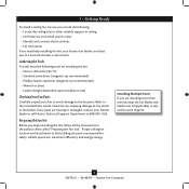
... one fan, keep the fan blades and blade irons (if applicable) in the pullout sheet called "Preparing the Fan Site." Proper ceiling fan location and attachment to the included Parts Guide. Check for and install wood screws. • Identify and connect electrical wires. • Lift 40 pounds. Installing Multiple Fans? If you begin installing the fan, follow all the instructions in sets, as they were shipped. 4 42678-01 • 06/08/09 • Hunter Fan Company
... one fan, keep the fan blades and blade irons (if applicable) in the pullout sheet called "Preparing the Fan Site." Proper ceiling fan location and attachment to the included Parts Guide. Check for and install wood screws. • Identify and connect electrical wires. • Lift 40 pounds. Installing Multiple Fans? If you begin installing the fan, follow all the instructions in sets, as they were shipped. 4 42678-01 • 06/08/09 • Hunter Fan Company
Owner's Manual
Page 5
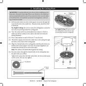
... the ceiling plate into the pilot holes you drilled in diameter. Note: The isolators should be flush against the ceiling. 2-6. For proper alignment use lubricants on each other. Flat Washer Toward Ceiling Peak For Angled Ceilings: Be sure to the outlet box and associated wall switch location. Pass the screws through the hole in the outlet box. Ceiling Plate 3" Wood Screw Steps 2-3 - 2-6 5 42678-01 • 06/08/09 • Hunter Fan Company...
... the ceiling plate into the pilot holes you drilled in diameter. Note: The isolators should be flush against the ceiling. 2-6. For proper alignment use lubricants on each other. Flat Washer Toward Ceiling Peak For Angled Ceilings: Be sure to the outlet box and associated wall switch location. Pass the screws through the hole in the outlet box. Ceiling Plate 3" Wood Screw Steps 2-3 - 2-6 5 42678-01 • 06/08/09 • Hunter Fan Company...
Owner's Manual
Page 6
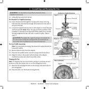
... not remove this is fully installed, 2-3 threads on one side of the pin in the washer with three low profile screws. Raise the fan and align the slots in these installation instructions. 3-1. the coating prevents the downrod from the fan. Standard or Angled Mounting Steps 3-2 - 3-3 Downrod Setscrew Canopy Canopy Trim Ring Low Profile Mounting Steps 3-5 - 3-6 Low Profile Screws Green Ground Wire Canopy Trim Ring Low Profile Washer Canopy Low Profile Screw Step 3-6 (Detail) Adapter Low Profile Screw Low Profile Washer 6 42678-01 • 06/08/09 • Hunter Fan Company...
... not remove this is fully installed, 2-3 threads on one side of the pin in the washer with three low profile screws. Raise the fan and align the slots in these installation instructions. 3-1. the coating prevents the downrod from the fan. Standard or Angled Mounting Steps 3-2 - 3-3 Downrod Setscrew Canopy Canopy Trim Ring Low Profile Mounting Steps 3-5 - 3-6 Low Profile Screws Green Ground Wire Canopy Trim Ring Low Profile Washer Canopy Low Profile Screw Step 3-6 (Detail) Adapter Low Profile Screw Low Profile Washer 6 42678-01 • 06/08/09 • Hunter Fan Company...
Owner's Manual
Page 7
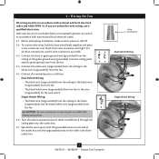
... the ceiling to the black (ungrounded) and the black/white wire (ungrounded) from the fan. 4-4. If you are unfamiliar with wiring, use switch in accordance with the grounded wires on one side of the outlet box and the ungrounded wires on the other side of the outlet box. 7 42678-01 • 06/08/09 • Hunter Fan Company fsdfsdf Wire Connector Dual Switch Wiring Single Switch Wiring Wall switches are visible after making connections. 4-6. For...
... the ceiling to the black (ungrounded) and the black/white wire (ungrounded) from the fan. 4-4. If you are unfamiliar with wiring, use switch in accordance with the grounded wires on one side of the outlet box and the ungrounded wires on the other side of the outlet box. 7 42678-01 • 06/08/09 • Hunter Fan Company fsdfsdf Wire Connector Dual Switch Wiring Single Switch Wiring Wall switches are visible after making connections. 4-6. For...
Owner's Manual
Page 8
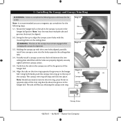
.../09 • Hunter Fan Company Align the tabs on the ceiling plate. Note: Should you use a magnetic tip screwdriver for alignment. 5-3. Partially install a canopy screw into place. Rotate the hanger ball so the tab in the canopy is recommended you need to fall. Verify that must remain engaged while swinging the canopy for the following steps could cause the fan to remove the trim ring, press firmly...
.../09 • Hunter Fan Company Align the tabs on the ceiling plate. Note: Should you use a magnetic tip screwdriver for alignment. 5-3. Partially install a canopy screw into place. Rotate the hanger ball so the tab in the canopy is recommended you need to fall. Verify that must remain engaged while swinging the canopy for the following steps could cause the fan to remove the trim ring, press firmly...

Owner's Manual
Page 9
... Blade Mounting Screw Step 6-4 9 42678-01 • 06/08/09 • Hunter Fan Company For each blade to the fan. Insert the second blade mounting screw, then securely tighten both mounting screws. Attach each blade, insert one blade mounting screw through the blade iron, and attach lightly to a blade iron using three blade assembly screws. If you used grommets, the blades may include blade grommets. Remove the blade mounting screws and rubber shipping bumpers from the motor. 6 • Assembling the Blades Hunter fans use several styles of fan blade irons (brackets...
... Blade Mounting Screw Step 6-4 9 42678-01 • 06/08/09 • Hunter Fan Company For each blade to the fan. Insert the second blade mounting screw, then securely tighten both mounting screws. Attach each blade, insert one blade mounting screw through the blade iron, and attach lightly to a blade iron using three blade assembly screws. If you used grommets, the blades may include blade grommets. Remove the blade mounting screws and rubber shipping bumpers from the motor. 6 • Assembling the Blades Hunter fans use several styles of fan blade irons (brackets...
Owner's Manual
Page 10
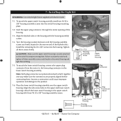
... 7-1 - 7-3 Housing Assembly Screw 7-5. Place the lower switch housing assembly over the upper switch housing. 7 • Installing the Light Kit WARNING: Use only the light fixture supplied with three #6-32 x 3/8" housing assembly screws. Feed the upper plug connector through the center opening of the keyhole slots. Align the keyhole slots in the upper and lower switch housings. To attach the lower switch housing, connect the upper plug connector from the motor to the switch housing mounting plate. Note: Both plug connectors are polarized and will only fit together...
... 7-1 - 7-3 Housing Assembly Screw 7-5. Place the lower switch housing assembly over the upper switch housing. 7 • Installing the Light Kit WARNING: Use only the light fixture supplied with three #6-32 x 3/8" housing assembly screws. Feed the upper plug connector through the center opening of the keyhole slots. Align the keyhole slots in the upper and lower switch housings. To attach the lower switch housing, connect the upper plug connector from the motor to the switch housing mounting plate. Note: Both plug connectors are polarized and will only fit together...
Owner's Manual
Page 11
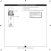
Install the three 60-Watt candelabra light bulbs (included). Steps 7-8 - 7-9 11 42678-01 • 06/08/09 • Hunter Fan Company 7 • Installing the Light Kit (continued) Shade Light Bulb 7-7. Install the shades. 7-9. Remove the protective wrap from each of the shades. 7-8. Remove the plastic from the silhouette on the motor housing before starting the fan.
Install the three 60-Watt candelabra light bulbs (included). Steps 7-8 - 7-9 11 42678-01 • 06/08/09 • Hunter Fan Company 7 • Installing the Light Kit (continued) Shade Light Bulb 7-7. Install the shades. 7-9. Remove the protective wrap from each of the shades. 7-8. Remove the plastic from the silhouette on the motor housing before starting the fan.
Owner's Manual
Page 12
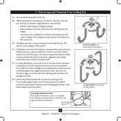
...; Pull the chain slowly to change settings. • Release slowly to the opposite position. Slide the reversing switch on electrical power to a complete stop. 8 • Operating and Cleaning Your Ceiling Fan 8-1. The chain has two settings: ON and OFF. 8-4. A vacuum cleaner brush nozzle can remove heavier dust. The light pull chain controls the power to the fan. Ceiling fans work best by blowing air downward (counterclockwise blade rotation) in warm weather to prevent scratching. In warm weather, use downward air...
...; Pull the chain slowly to change settings. • Release slowly to the opposite position. Slide the reversing switch on electrical power to a complete stop. 8 • Operating and Cleaning Your Ceiling Fan 8-1. The chain has two settings: ON and OFF. 8-4. A vacuum cleaner brush nozzle can remove heavier dust. The light pull chain controls the power to the fan. Ceiling fans work best by blowing air downward (counterclockwise blade rotation) in warm weather to prevent scratching. In warm weather, use downward air...
Owner's Manual
Page 13
....hunterfan.com. Tighten the blade assembly screws and blade iron armature screws until snug. 2. Check the plug connection in the switch housing. 4. If so, replace all blade iron screws. 3. Tighten all the blades. fan does not move. 1. Push motor reversing switch firmly left or right to balance the fan. 2. Problem: Excessive wobbling. 1. Check to the wiring the fan section. 3. Loosen canopy, check all connections according to make sure the wattage and type of light bulbs installed match the specifications on . 6. Apague el ventilador...
....hunterfan.com. Tighten the blade assembly screws and blade iron armature screws until snug. 2. Check the plug connection in the switch housing. 4. If so, replace all blade iron screws. 3. Tighten all the blades. fan does not move. 1. Push motor reversing switch firmly left or right to balance the fan. 2. Problem: Excessive wobbling. 1. Check to the wiring the fan section. 3. Loosen canopy, check all connections according to make sure the wattage and type of light bulbs installed match the specifications on . 6. Apague el ventilador...
Parts Guide
Page 1
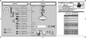
... 4 Canopy Trim Ring 8 Setscrew 27 Low Profile Washer 62 Canopy Screw 64 Wood Screw 65 Wood Screw 68 Flat Washer 71 Mounting Isolator 100 * Screw, Low Profile 7 Hanger Ball / Downrod Assembly 44 Blade Iron Set 46 Blade Set 47 Screw, Blade Iron Armature 60 Hardware Kit 66 Blade Grommet 67 Blade Assembly Screw 69 Screw, Machine, 6-32 70 Wire Connector 131 Screw, Switch Housing Assembly 75 Balancing Kit 49 Light Kit Assembly 134 Decorative Sleeve 78 Pull Chain 76 Pull Chain Pendant 76 Pull Chain Pendant 202 Light bulb / Bulb 150 Globe/Shade Model # 21101...
... 4 Canopy Trim Ring 8 Setscrew 27 Low Profile Washer 62 Canopy Screw 64 Wood Screw 65 Wood Screw 68 Flat Washer 71 Mounting Isolator 100 * Screw, Low Profile 7 Hanger Ball / Downrod Assembly 44 Blade Iron Set 46 Blade Set 47 Screw, Blade Iron Armature 60 Hardware Kit 66 Blade Grommet 67 Blade Assembly Screw 69 Screw, Machine, 6-32 70 Wire Connector 131 Screw, Switch Housing Assembly 75 Balancing Kit 49 Light Kit Assembly 134 Decorative Sleeve 78 Pull Chain 76 Pull Chain Pendant 76 Pull Chain Pendant 202 Light bulb / Bulb 150 Globe/Shade Model # 21101...


