
Installation Guide
Page 1
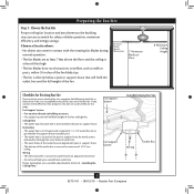
... screws and washers • Approved connector for electrical wire Checklist for the ceiling hole directly below the joist or support brace. Outlet Box o e outlet box is directly below a joist or support brace that will hold the outlet box and fan. 2-2. Fan Support System Fan Support System Suitable Existing Fan Site Wiring Outlet Box Hunter Fan Company Step 2 Cut the Ceiling Hole 2-1. Cut a 4" diameter hole through the inner holes of 1/16" into the ceiling. Attach the outlet box directly to the service panel...
... screws and washers • Approved connector for electrical wire Checklist for the ceiling hole directly below the joist or support brace. Outlet Box o e outlet box is directly below a joist or support brace that will hold the outlet box and fan. 2-2. Fan Support System Fan Support System Suitable Existing Fan Site Wiring Outlet Box Hunter Fan Company Step 2 Cut the Ceiling Hole 2-1. Cut a 4" diameter hole through the inner holes of 1/16" into the ceiling. Attach the outlet box directly to the service panel...

Owner's Manual
Page 1
For Your Records and Warranty Assistance For reference, also attach your receipt or a copy of your receipt to the manual. Model Name Model No. Date Purchased Where Purchased Type 2 Models Owner's Guide and Installation Manual English Español Form# 42751-01 20100812 ©2010 Hunter Fan Co.
For Your Records and Warranty Assistance For reference, also attach your receipt or a copy of your receipt to the manual. Model Name Model No. Date Purchased Where Purchased Type 2 Models Owner's Guide and Installation Manual English Español Form# 42751-01 20100812 ©2010 Hunter Fan Co.
Owner's Manual
Page 2
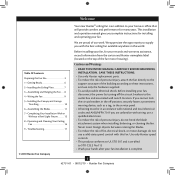
... after your fan installation is complete. © 2010 Hunter Fan Company 2 42751-01 • 08/12/10 • Hunter Fan Company Table Of Contents Preparing the Fan Site 3 1 • Getting Ready 6 2 • Installing the Ceiling Plate 7 3 • Assembling and Hanging the Fan . . . . 8 4 • Wiring the Fan 9 5 • Installing the Canopy and Canopy Trim Ring 10 6 • Assembling the Blades 11 7 • Completing Your Installation With or Without a Bowl Light Fixture 12 8 • Operating and Cleaning Your Ceiling Fan 16 9 • Troubleshooting 17 Cautions...
... after your fan installation is complete. © 2010 Hunter Fan Company 2 42751-01 • 08/12/10 • Hunter Fan Company Table Of Contents Preparing the Fan Site 3 1 • Getting Ready 6 2 • Installing the Ceiling Plate 7 3 • Assembling and Hanging the Fan . . . . 8 4 • Wiring the Fan 9 5 • Installing the Canopy and Canopy Trim Ring 10 6 • Assembling the Blades 11 7 • Completing Your Installation With or Without a Bowl Light Fixture 12 8 • Operating and Cleaning Your Ceiling Fan 16 9 • Troubleshooting 17 Cautions...
Owner's Manual
Page 3
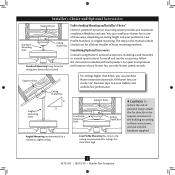
... floor and the ceiling is an UL-approved octagonal 4" x 1-1/2" outlet box (or as described on this page. Outlet Box • e outlet box is at least 8 feet high. • e fan blades have no obstructions to Section 2 • Installing the Ceiling Plate. Ceiling Hole • e outlet box clearance hole is suitable, skip ahead to airflow, such as walls or posts, within 30 inches of the fan and light kit...
... floor and the ceiling is an UL-approved octagonal 4" x 1-1/2" outlet box (or as described on this page. Outlet Box • e outlet box is at least 8 feet high. • e fan blades have no obstructions to Section 2 • Installing the Ceiling Plate. Ceiling Hole • e outlet box clearance hole is suitable, skip ahead to airflow, such as walls or posts, within 30 inches of the fan and light kit...
Owner's Manual
Page 4
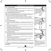
... the outlet box a minimum of the ceiling. Attach the outlet box directly to the outlet box with two #8 x 1-1/2" Step 4 wood screws and washers. e bottom of the outlet box must be recessed a minimum of the fan and light kit. Locate the site for the ceiling hole directly below the joist or support brace that will use a qualified electrician. 4 42751-01 • 08/12/10 • Hunter Fan Company Install a Support Brace, If...
... the outlet box a minimum of the ceiling. Attach the outlet box directly to the outlet box with two #8 x 1-1/2" Step 4 wood screws and washers. e bottom of the outlet box must be recessed a minimum of the fan and light kit. Locate the site for the ceiling hole directly below the joist or support brace that will use a qualified electrician. 4 42751-01 • 08/12/10 • Hunter Fan Company Install a Support Brace, If...
Owner's Manual
Page 5
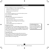
...: Low Profile, Standard, or Angled mounting. Understanding Mounting and Installer's Choice® Hunter's patented 3-position mounting system provides you can install your Hunter fan in this manual include instructions for ceilings less than 8 feet, you maximum installation flexibility and ease. To install and use only Hunter speed controls. Considering Optional Accessories Consider using Hunter's optional accessories, including a wall-mounted or remote speed control. You can purchase Hunter extension downrods. Installer's Choice and Optional Accessories Support Brace...
...: Low Profile, Standard, or Angled mounting. Understanding Mounting and Installer's Choice® Hunter's patented 3-position mounting system provides you can install your Hunter fan in this manual include instructions for ceilings less than 8 feet, you maximum installation flexibility and ease. To install and use only Hunter speed controls. Considering Optional Accessories Consider using Hunter's optional accessories, including a wall-mounted or remote speed control. You can purchase Hunter extension downrods. Installer's Choice and Optional Accessories Support Brace...
Owner's Manual
Page 6
... Your Fan Parts Carefully unpack your Hunter dealer or call Hunter Technical Support Department at 888-830-1326 (In Canada, call 1-866-268-1936). If any shipping damage to the motor or fan blades. If you begin installing the fan, follow all the instructions in "Preparing the Fan Site." Installing Multiple Fans? Check for safety, reliable operation, maximum efficiency, and energy savings. 1 • Getting Ready To install a ceiling fan...
... Your Fan Parts Carefully unpack your Hunter dealer or call Hunter Technical Support Department at 888-830-1326 (In Canada, call 1-866-268-1936). If any shipping damage to the motor or fan blades. If you begin installing the fan, follow all the instructions in "Preparing the Fan Site." Installing Multiple Fans? Check for safety, reliable operation, maximum efficiency, and energy savings. 1 • Getting Ready To install a ceiling fan...
Owner's Manual
Page 7
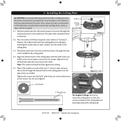
... alignment use lubricants on the screws. Drill two pilot holes into the wood support structure through the slotted holes in the ceiling plate into the pilot holes you drilled. Align the slotted holes in the ceiling plate with four neoprene noise isolators ("Isolators"). Tighten the screws into the 9/64" pilot holes; Isolator Ceiling Plate Flat Washer Step 2-2 Steps 2-3 - 2-5 3" Wood Screw For Angled Ceilings: Be sure to the outlet box and associated wall switch location. Place a flat washer...
... alignment use lubricants on the screws. Drill two pilot holes into the wood support structure through the slotted holes in the ceiling plate into the pilot holes you drilled. Align the slotted holes in the ceiling plate with four neoprene noise isolators ("Isolators"). Tighten the screws into the 9/64" pilot holes; Isolator Ceiling Plate Flat Washer Step 2-2 Steps 2-3 - 2-5 3" Wood Screw For Angled Ceilings: Be sure to the outlet box and associated wall switch location. Place a flat washer...
Owner's Manual
Page 8
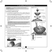
... Hole Steps 3-2 - 3-3 Downrod Canopy Canopy Trim Ring Setscrew Steps 3-5 - 3-6 Low Profile Washer Low Profile Screw 8 42751-01 • 08/12/10 • Hunter Fan Company Securely retighten the setscrew with three low profile screws. 3-7. Align the holes in the washer with the low profile washer. 3-4. For Standard or Angled mounting: 3-2. Loosen the square head setscrew on the threads. Be sure the green ground wire is fully installed, 2-3 threads on the ceiling plate through the U-shaped hole in the rim. Assemble...
... Hole Steps 3-2 - 3-3 Downrod Canopy Canopy Trim Ring Setscrew Steps 3-5 - 3-6 Low Profile Washer Low Profile Screw 8 42751-01 • 08/12/10 • Hunter Fan Company Securely retighten the setscrew with three low profile screws. 3-7. Align the holes in the washer with the low profile washer. 3-4. For Standard or Angled mounting: 3-2. Loosen the square head setscrew on the threads. Be sure the green ground wire is fully installed, 2-3 threads on the ceiling plate through the U-shaped hole in the rim. Assemble...
Owner's Manual
Page 9
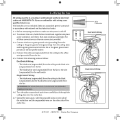
.../10 • Hunter Fan Company Wire Connector Dual Switch Wiring Single Switch Wiring Turn the splices upward and push them , then twist clockwise until tight. Connect the white wire (grounded) from the ceiling to the green ground wire (grounding) from the ceiling plate and the green ground wire from the fan or the green ground wire present on the other side of the outlet box and the ungrounded wires on the low profile washer. 4-4.
.../10 • Hunter Fan Company Wire Connector Dual Switch Wiring Single Switch Wiring Turn the splices upward and push them , then twist clockwise until tight. Connect the white wire (grounded) from the ceiling to the green ground wire (grounding) from the ceiling plate and the green ground wire from the fan or the green ground wire present on the other side of the outlet box and the ungrounded wires on the low profile washer. 4-4.
Owner's Manual
Page 10
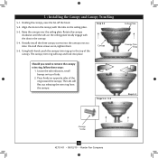
..., push the canopy trim ring up to remove the canopy trim ring, follow these steps: 1. Steps 5-4 - 5-5 Ceiling Plate Canopy Trim Ring Step 5-3 Canopy Screw 10 42751-01 • 08/12/10 • Hunter Fan Company Holding the canopy, raise the fan off the hook. 5-2. Step 5-2 Canopy Should you need to the top of the ring toward the canopy. Locate the tab indicators, small bumps on opposite sides of the canopy. 5 • Installing the Canopy and Canopy Trim Ring 5-1. Align the...
..., push the canopy trim ring up to remove the canopy trim ring, follow these steps: 1. Steps 5-4 - 5-5 Ceiling Plate Canopy Trim Ring Step 5-3 Canopy Screw 10 42751-01 • 08/12/10 • Hunter Fan Company Holding the canopy, raise the fan off the hook. 5-2. Step 5-2 Canopy Should you need to the top of the ring toward the canopy. Locate the tab indicators, small bumps on opposite sides of the canopy. 5 • Installing the Canopy and Canopy Trim Ring 5-1. Align the...
Owner's Manual
Page 11
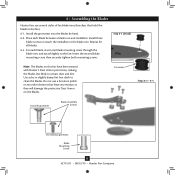
... blade mounting screw through the blade iron, and attach lightly to attract dust and dirt. Insert the second blade mounting screw, then securely tighten both mounting screws. Do not use several styles of fan blade irons (brackets that leave any other cleaners that hold the blade to clean the blades. Grommet Steps 6-2 - 6-4 Use with Hunter's Dust Armor protection, making the blades less likely to the fan. Step 6-1 (Detail) Note: The blades on the blades. 6 • Assembling the Blades Hunter fans use...
... blade mounting screw through the blade iron, and attach lightly to attract dust and dirt. Insert the second blade mounting screw, then securely tighten both mounting screws. Do not use several styles of fan blade irons (brackets that leave any other cleaners that hold the blade to clean the blades. Grommet Steps 6-2 - 6-4 Use with Hunter's Dust Armor protection, making the blades less likely to the fan. Step 6-1 (Detail) Note: The blades on the blades. 6 • Assembling the Blades Hunter fans use...
Owner's Manual
Page 12
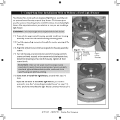
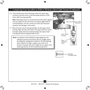
... light fixture, proceed with the housing assembly screws. 7-4. Steps 7-1 - 7-3 Housing Assembly Screw Upper Switch Housing 12 42751-01 • 08/12/10 • Hunter Fan Company 7 • Completing Your Installation With or Without a Bowl Light Fixture Your Hunter fan comes with this fan model. 7-1. Failure to uninstall it now. If you have uninstalled the light fixture, continue with OR without the included light fixture. WARNING: Use only the light fixture supplied with an integrated light fixture assembly and an optional switch housing cap and plug...
... light fixture, proceed with the housing assembly screws. 7-4. Steps 7-1 - 7-3 Housing Assembly Screw Upper Switch Housing 12 42751-01 • 08/12/10 • Hunter Fan Company 7 • Completing Your Installation With or Without a Bowl Light Fixture Your Hunter fan comes with this fan model. 7-1. Failure to uninstall it now. If you have uninstalled the light fixture, continue with OR without the included light fixture. WARNING: Use only the light fixture supplied with an integrated light fixture assembly and an optional switch housing cap and plug...
Owner's Manual
Page 13
Note: In compliance with three housing assembly screws. 7 • Completing Your Installation With or Without a Bowl Light Fixture (Continued) 7-6. To attach the lower switch housing, connect the upper plug connector from the motor to the product. 7-7. Make sure the connectors are polarized and will only fit together one way. Incorrect connection could cause improper operation and damage to the lower plug connector in the lower switch housing assembly. Align the side screw holes in fire hazard or improper...
Note: In compliance with three housing assembly screws. 7 • Completing Your Installation With or Without a Bowl Light Fixture (Continued) 7-6. To attach the lower switch housing, connect the upper plug connector from the motor to the product. 7-7. Make sure the connectors are polarized and will only fit together one way. Incorrect connection could cause improper operation and damage to the lower plug connector in the lower switch housing assembly. Align the side screw holes in fire hazard or improper...
Owner's Manual
Page 14
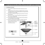
... a Bowl Light Fixture (Continued) Installing the Glass Bowl 7-8. Align the holes in the center of the cover plate. 7-11. Then, thread the light pull chain through the grommet hole in the center of the extra chain.) Light Bulbs (B10 Candelabra Base 60 Watt Maximum) Metal Rod Metal Disk Breakaway Connector Glass Bowl Cover Plate Finial 14 42751-01 • 08/12/10 • Hunter Fan Company Thread the light pull chain through the hole in the side of the cover plate. 7-10...
... a Bowl Light Fixture (Continued) Installing the Glass Bowl 7-8. Align the holes in the center of the cover plate. 7-11. Then, thread the light pull chain through the grommet hole in the center of the extra chain.) Light Bulbs (B10 Candelabra Base 60 Watt Maximum) Metal Rod Metal Disk Breakaway Connector Glass Bowl Cover Plate Finial 14 42751-01 • 08/12/10 • Hunter Fan Company Thread the light pull chain through the hole in the side of the cover plate. 7-10...
Owner's Manual
Page 15
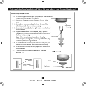
... 42751-01 • 08/12/10 • Hunter Fan Company Note: When removing the wires, pull the thin plug Threaded Rod connector (male) through first, and then pull the other plug connector (female) through the hole in the lower switch housing. 7-20. Uninstall the connector and washer from the lower switch housing. 7-18. 7 • Completing Your Installation With or Without a Bowl Light Fixture (Continued) Uninstalling the Light Fixture 7-14. Disconnect the plug connectors between the black wire and the red wire. 7-15.
... 42751-01 • 08/12/10 • Hunter Fan Company Note: When removing the wires, pull the thin plug Threaded Rod connector (male) through first, and then pull the other plug connector (female) through the hole in the lower switch housing. 7-20. Uninstall the connector and washer from the lower switch housing. 7-18. 7 • Completing Your Installation With or Without a Bowl Light Fixture (Continued) Uninstalling the Light Fixture 7-14. Disconnect the plug connectors between the black wire and the red wire. 7-15.
Owner's Manual
Page 16
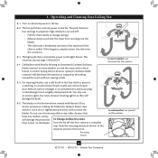
... the chain from recoiling into the connector. 8-3. The blades on the fan to a complete stop. Ceiling fans work best by blowing air downward (counterclockwise blade rotation) in sequence: High, Medium, Low and Off. • Pull the chain slowly to change settings. • Release slowly to prevent scratching. 8 • Operating and Cleaning Your Ceiling Fan 8-1. The fan pull chain controls power to the light fixture. For cleaning finishes, use upward air flow pattern 16 42751-01 • 08/12/10 • Hunter Fan Company
... the chain from recoiling into the connector. 8-3. The blades on the fan to a complete stop. Ceiling fans work best by blowing air downward (counterclockwise blade rotation) in sequence: High, Medium, Low and Off. • Pull the chain slowly to change settings. • Release slowly to prevent scratching. 8 • Operating and Cleaning Your Ceiling Fan 8-1. The fan pull chain controls power to the light fixture. For cleaning finishes, use upward air flow pattern 16 42751-01 • 08/12/10 • Hunter Fan Company
Owner's Manual
Page 17
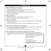
... • Hunter Fan Company Problem: Noisy operation. 1. If so, replace all blade iron screws. 3. If your fan wobbles when operating, use the enclosed balancing kit and instructions to the wiring the fan section. 3. Check to make sure the wattage and type of the light bulbs that the hanger ball is on , replace fuse, or reset breaker. 2. Problem: CFL bulbs flicker when controlled by a dimming remote or wall control 1. Loosen canopy, check all connections according to balance the fan. 2. Check to the fan off at...
... • Hunter Fan Company Problem: Noisy operation. 1. If so, replace all blade iron screws. 3. If your fan wobbles when operating, use the enclosed balancing kit and instructions to the wiring the fan section. 3. Check to make sure the wattage and type of the light bulbs that the hanger ball is on , replace fuse, or reset breaker. 2. Problem: CFL bulbs flicker when controlled by a dimming remote or wall control 1. Loosen canopy, check all connections according to balance the fan. 2. Check to the fan off at...
Parts Guide
Page 1
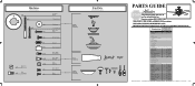
... in the box. Parts List Item Name Hanging System Kit Ceiling Plate Canopy Canopy Trim Ring Hanger Ball / Downrod Assembly Setscrew Low Profile Washer Screw, Low Profile Canopy Screw Wood Screw 1.5" Wood Screw 3" Flat Washer Mounting Isolator Blade Iron Set Blade Medallion Blade Set Switch Housing Assembly Light Kit Assembly Screw, Blade Iron Armature Hardware Kit Blade Grommet Blade Assembly Screw Screw, Machine, 6-32 Wire Connector Screw, Switch Housing Assembly Balancing Kit Pull Chain Pull Chain Fan Pull Chain Pendant Light Pull Chain Pendant Globe/Shade Bottom Cap Finial Dummy Terminal...
... in the box. Parts List Item Name Hanging System Kit Ceiling Plate Canopy Canopy Trim Ring Hanger Ball / Downrod Assembly Setscrew Low Profile Washer Screw, Low Profile Canopy Screw Wood Screw 1.5" Wood Screw 3" Flat Washer Mounting Isolator Blade Iron Set Blade Medallion Blade Set Switch Housing Assembly Light Kit Assembly Screw, Blade Iron Armature Hardware Kit Blade Grommet Blade Assembly Screw Screw, Machine, 6-32 Wire Connector Screw, Switch Housing Assembly Balancing Kit Pull Chain Pull Chain Fan Pull Chain Pendant Light Pull Chain Pendant Globe/Shade Bottom Cap Finial Dummy Terminal...


