Installation Instructions
Page 1
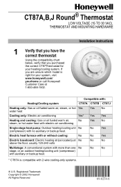
... auxiliary or backup heat. CT87A,B,J Round® Thermostat LOW VOLTAGE (15 TO 30 VAC), THERMOSTAT AND MOUNTING HARDWARE 1 Verify that you have the correct thermostat Using the compatibility chart below, verify that you are unsure which model is compatible with 2-wire cooling-only systems. ® U.S. No No * CT87A is right for your system, visit www.honeywell.com/ yourhome...
... auxiliary or backup heat. CT87A,B,J Round® Thermostat LOW VOLTAGE (15 TO 30 VAC), THERMOSTAT AND MOUNTING HARDWARE 1 Verify that you have the correct thermostat Using the compatibility chart below, verify that you are unsure which model is compatible with 2-wire cooling-only systems. ® U.S. No No * CT87A is right for your system, visit www.honeywell.com/ yourhome...
Installation Instructions
Page 2
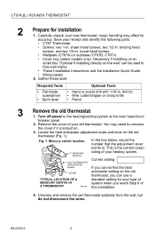
... the following parts: • CT87 Thermostat • Screws: two 1-in . OLD THERMOSTAT ANTICIPATOR SCALE Current setting: If you cannot find the heat LEVER anticipator setting on the old thermostat, you can be used to . CT87A,B,J ROUND® THERMOSTAT 2 Prepare for your type of MERCURY SWITCH IN A THERMOSTAT system when you reach Step 8 of your heating system. This is locked on the...
... the following parts: • CT87 Thermostat • Screws: two 1-in . OLD THERMOSTAT ANTICIPATOR SCALE Current setting: If you cannot find the heat LEVER anticipator setting on the old thermostat, you can be used to . CT87A,B,J ROUND® THERMOSTAT 2 Prepare for your type of MERCURY SWITCH IN A THERMOSTAT system when you reach Step 8 of your heating system. This is locked on the...

Installation Instructions
Page 3
stat (Fig. 2). Fig. 4. Labeling wires. Wrapping wires. Fig. 2. M19086 MERCURY NOTICE Fig. 3. Label the wires using the letter of the terminal on the old thermo- Disconnect the wires from the old thermostat and wrap them around a pencil to Fig. 4 as you work. Installing wallplate/subbase on ...(wallplate shown). Do not label the wires by color. 6. WIRES THROUGH WALL OPENING If this control, or of this thermostat is replacing a control that came with the CT87. CT87A,B,J ROUND® THERMOSTAT 5. COVER RING WALLPLATE NO. 4 X 1 INCH SHEET METAL SCREWS...
stat (Fig. 2). Fig. 4. Labeling wires. Wrapping wires. Fig. 2. M19086 MERCURY NOTICE Fig. 3. Label the wires using the letter of the terminal on the old thermo- Disconnect the wires from the old thermostat and wrap them around a pencil to Fig. 4 as you work. Installing wallplate/subbase on ...(wallplate shown). Do not label the wires by color. 6. WIRES THROUGH WALL OPENING If this control, or of this thermostat is replacing a control that came with the CT87. CT87A,B,J ROUND® THERMOSTAT 5. COVER RING WALLPLATE NO. 4 X 1 INCH SHEET METAL SCREWS...
Installation Instructions
Page 4
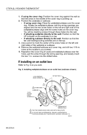
...) and wallplate/subbase over the cover ring. M20187 69-0274-6 4 Use a pencil to the wall: Position so that the fan and heating/cooling switches are aligned and the two screw holes on the left and right sides of the cover ring is on top. • If...into the drilled holes. BINDING HEAD SCREW (2) OUTLET BOX 1 2 COVER RING SUBBASE 1/4 IN. CT87A,B,J ROUND® THERMOSTAT 1. Rotate the wallplate/subbase until the wiring openings are on the top. 3. ROUND HEAD SCREW (2) A THERMOSTAT WIRING HOLE 1 THE TWO INNER HOLES ARE USED WITH WALLPLATE. 2 IF OUTLET BOX IS HORIZONTAL, MOUNT ...
...) and wallplate/subbase over the cover ring. M20187 69-0274-6 4 Use a pencil to the wall: Position so that the fan and heating/cooling switches are aligned and the two screw holes on the left and right sides of the cover ring is on top. • If...into the drilled holes. BINDING HEAD SCREW (2) OUTLET BOX 1 2 COVER RING SUBBASE 1/4 IN. CT87A,B,J ROUND® THERMOSTAT 1. Rotate the wallplate/subbase until the wiring openings are on the top. 3. ROUND HEAD SCREW (2) A THERMOSTAT WIRING HOLE 1 THE TWO INNER HOLES ARE USED WITH WALLPLATE. 2 IF OUTLET BOX IS HORIZONTAL, MOUNT ...

Installation Instructions
Page 5
...screw slots on the cover ring with the outlet box screw holes, and attach the cover ring to maintain accu- screws. 4. rate thermostat temperature. 1. Place the wallplate or subbase over the cover ring so that the wiring holes line up . 2. Rotate the wallplate/subbase... posts directly below the Heat and Fan indicators. screws, through the screw holes on the bottom left and right sides of the cover ring is level. 5 69-0274-6 SPIRIT LEVEL LEVELING POSTS (2) OPENING FOR THERMOSTAT WIRING MOUNTING SLOTS M3319A 2. CT87A,B,J ROUND® THERMOSTAT 1. Leveling the wallplate....
...screw slots on the cover ring with the outlet box screw holes, and attach the cover ring to maintain accu- screws. 4. rate thermostat temperature. 1. Place the wallplate or subbase over the cover ring so that the wiring holes line up . 2. Rotate the wallplate/subbase... posts directly below the Heat and Fan indicators. screws, through the screw holes on the bottom left and right sides of the cover ring is level. 5 69-0274-6 SPIRIT LEVEL LEVELING POSTS (2) OPENING FOR THERMOSTAT WIRING MOUNTING SLOTS M3319A 2. CT87A,B,J ROUND® THERMOSTAT 1. Leveling the wallplate....

Installation Instructions
Page 6
Fitting wires under the terminal screws. Strip the wire insulation as needed to both the B and O terminals. 2. Loosen the terminal screws and slip each old thermostat wire with its matching terminal. 4. See Fig. 8 through 13 wiring diagrams. Wiring Cross-reference Wire Label R, RH, 4, V Rc, R W, W1, H Y, Y1, M G, F B O See Fig. 13 Connect to ... to match each wire beneath its corresponding terminal on the CT87 wallplate or subbase. STRIP 5/16 in . [11 mm] BARRIER M1279 3. FOR STRAIGHT CONNECTION- CT87A,B,J ROUND® THERMOSTAT 6 Wire the...
Fitting wires under the terminal screws. Strip the wire insulation as needed to both the B and O terminals. 2. Loosen the terminal screws and slip each old thermostat wire with its matching terminal. 4. See Fig. 8 through 13 wiring diagrams. Wiring Cross-reference Wire Label R, RH, 4, V Rc, R W, W1, H Y, Y1, M G, F B O See Fig. 13 Connect to ... to match each wire beneath its corresponding terminal on the CT87 wallplate or subbase. STRIP 5/16 in . [11 mm] BARRIER M1279 3. FOR STRAIGHT CONNECTION- CT87A,B,J ROUND® THERMOSTAT 6 Wire the...

Installation Instructions
Page 7
COOL • OFF • HEAT FAN ON RH G RC Y W AUTO • CT87B SUBBASE POWER FAN COOL TO SYSTEM HEAT JUMPER RH TO RC M20185 7 69-0274-6 CT87B for a 3-wire hot water heating only system. CT87A WALLPLATE R Y W POWER HEAT TO SYSTEM M20183 Fig. 9. R Y W CT87A WALLPLATE WIRE LABELS (LETTERS ON ORIGINAL THERMOSTAT TERMINALS) R 3-WIRE W HOT WATER ZONE VALVE B M20184 Fig. 10. CT87A for a 4-wire heating/cooling system. CT87A,B,J ROUND® THERMOSTAT Fig. 8. CT87A for a 2-wire heating only system.
COOL • OFF • HEAT FAN ON RH G RC Y W AUTO • CT87B SUBBASE POWER FAN COOL TO SYSTEM HEAT JUMPER RH TO RC M20185 7 69-0274-6 CT87B for a 3-wire hot water heating only system. CT87A WALLPLATE R Y W POWER HEAT TO SYSTEM M20183 Fig. 9. R Y W CT87A WALLPLATE WIRE LABELS (LETTERS ON ORIGINAL THERMOSTAT TERMINALS) R 3-WIRE W HOT WATER ZONE VALVE B M20184 Fig. 10. CT87A for a 4-wire heating/cooling system. CT87A,B,J ROUND® THERMOSTAT Fig. 8. CT87A for a 2-wire heating only system.

Installation Instructions
Page 8
... SYSTEM COOL HEAT Fig. 12. M20225 COOL • OFF • HEAT FAN ON WG Y P R B O JUMPER W TO Y AUTO • CT87J SUBBASE HEAT FAN TO SYSTEM POWER COOL REVERSING VALVE HEAT REVERSING VALVE DO NOT ATTACH WIRES TO BOTH B AND O M20186 Fig. 13. M20228 69-0274-6 8 CT87J for a 5-wire heating/cooling system. CT87B for a 4-wire single stage heat pump. CT87A,B,J ROUND® THERMOSTAT...
... SYSTEM COOL HEAT Fig. 12. M20225 COOL • OFF • HEAT FAN ON WG Y P R B O JUMPER W TO Y AUTO • CT87J SUBBASE HEAT FAN TO SYSTEM POWER COOL REVERSING VALVE HEAT REVERSING VALVE DO NOT ATTACH WIRES TO BOTH B AND O M20186 Fig. 13. M20228 69-0274-6 8 CT87J for a 5-wire heating/cooling system. CT87B for a 4-wire single stage heat pump. CT87A,B,J ROUND® THERMOSTAT...

Installation Instructions
Page 9
Fig. 14. IMPORTANT: This prevents the thermostat from being damaged. CT87A,B,J ROUND® THERMOSTAT 7 Mount the thermostat 1. Tighten the three captive mounting screws as shown in Fig. 14. CAPTIVE SCREWS (3) M20227 9 69-0274-6 Place the thermostat over the wallplate or subbase so that holds the mercury switch in Fig. 15. Tightening mounting screws. HEAT ANTICIPATOR INDICATOR 1.2 .6 .5 .4 .3 .2 HOLE SUITABLE...
Fig. 14. IMPORTANT: This prevents the thermostat from being damaged. CT87A,B,J ROUND® THERMOSTAT 7 Mount the thermostat 1. Tighten the three captive mounting screws as shown in Fig. 14. CAPTIVE SCREWS (3) M20227 9 69-0274-6 Place the thermostat over the wallplate or subbase so that holds the mercury switch in Fig. 15. Tightening mounting screws. HEAT ANTICIPATOR INDICATOR 1.2 .6 .5 .4 .3 .2 HOLE SUITABLE...

Installation Instructions
Page 10
... heating system should stop. Your heating system: Steam Hot water heat High-efficiency warm air Standard warm air Electric heat Heat anticipator setting: 1.2 0.8 0.8 0.4 0.3 2. SETTING SCALE 69-0274-6 THERMOMETER 10 M9656 Using a pencil point, move the anticipator pointer down by .1 ampere. If you recorded in the table below .3 ampere. 9 Check heating/cooling operation Check heating 1. CT87A,B,J ROUND® THERMOSTAT 8 Set the heat anticipator...
... heating system should stop. Your heating system: Steam Hot water heat High-efficiency warm air Standard warm air Electric heat Heat anticipator setting: 1.2 0.8 0.8 0.4 0.3 2. SETTING SCALE 69-0274-6 THERMOMETER 10 M9656 Using a pencil point, move the anticipator pointer down by .1 ampere. If you recorded in the table below .3 ampere. 9 Check heating/cooling operation Check heating 1. CT87A,B,J ROUND® THERMOSTAT 8 Set the heat anticipator...

Installation Instructions
Page 11
... until the pointer on the CT87J model. 2. Heat On Auto The thermostat controls your heating system. Operation To set the System switch on the left to Cool on the top setting scale aligns with the heating or cooling system. 11 69-0274-6 Both the heating and cooling systems are off. CT87A,B,J ROUND® THERMOSTAT Check cooling IMPORTANT: To avoid damaging the...
... until the pointer on the CT87J model. 2. Heat On Auto The thermostat controls your heating system. Operation To set the System switch on the left to Cool on the top setting scale aligns with the heating or cooling system. 11 69-0274-6 Both the heating and cooling systems are off. CT87A,B,J ROUND® THERMOSTAT Check cooling IMPORTANT: To avoid damaging the...

Installation Instructions
Page 12
... you . Rev. 08-02 Printed in the possession of a consumer. CT87A,B,J ROUND® THERMOSTAT Limited One-Year Warranty Honeywell warrants this product, excluding battery, to be to repair or replace the product within a reasonable period of time. Honeywell's sole responsibility shall be free from defects in the workmanship or materials, under normal use and service...
... you . Rev. 08-02 Printed in the possession of a consumer. CT87A,B,J ROUND® THERMOSTAT Limited One-Year Warranty Honeywell warrants this product, excluding battery, to be to repair or replace the product within a reasonable period of time. Honeywell's sole responsibility shall be free from defects in the workmanship or materials, under normal use and service...


