
Owner's Manual
Page 1
M18539 1 69-1490 69-1490 Set Room FAN Auto On SYSTEM Cool Off Heat M18535 Em Ht Aux Ht Set Room Electronic Thermostat OWNER'S GUIDE FAN Auto On SYSTEM Cool Off Heat Em.Ht.
M18539 1 69-1490 69-1490 Set Room FAN Auto On SYSTEM Cool Off Heat M18535 Em Ht Aux Ht Set Room Electronic Thermostat OWNER'S GUIDE FAN Auto On SYSTEM Cool Off Heat Em.Ht.
Owner's Manual
Page 2
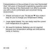
Batteries are not required because your temperature settings are held permanently in an effort to provide you to use. Congratulations on the purchase of this thermostat in memory. 69-1490 2 Over 100 years of Honeywell engineering expertise went into the making of your temperature setting. • Large digital display. You can easily read the current room temperature at a glance. • No need for you with a more comfortable and convenient living environment. • Simple and easy to change your new thermostat! The ▲ and ▼ keys make it easy for batteries.
Batteries are not required because your temperature settings are held permanently in an effort to provide you to use. Congratulations on the purchase of this thermostat in memory. 69-1490 2 Over 100 years of Honeywell engineering expertise went into the making of your temperature setting. • Large digital display. You can easily read the current room temperature at a glance. • No need for you with a more comfortable and convenient living environment. • Simple and easy to change your new thermostat! The ▲ and ▼ keys make it easy for batteries.
Owner's Manual
Page 3
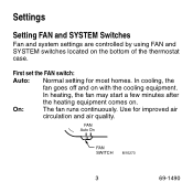
In cooling, the fan goes off and on the bottom of the thermostat case. FAN Auto On FAN SWITCH M10273 3 69-1490 On: The fan runs continuously. Settings Setting FAN and SYSTEM Switches Fan and system settings are controlled by using FAN and SYSTEM switches located on with the cooling equipment. Use for most homes. In heating, the fan may start a few minutes after the heating equipment comes on. First set the FAN switch: Auto: Normal setting for improved air circulation and air quality.
In cooling, the fan goes off and on the bottom of the thermostat case. FAN Auto On FAN SWITCH M10273 3 69-1490 On: The fan runs continuously. Settings Setting FAN and SYSTEM Switches Fan and system settings are controlled by using FAN and SYSTEM switches located on with the cooling equipment. Use for most homes. In heating, the fan may start a few minutes after the heating equipment comes on. First set the FAN switch: Auto: Normal setting for improved air circulation and air quality.
Owner's Manual
Page 8
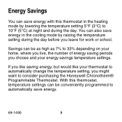
... where you live, the number of energy saving periods you choose and your thermostat to automatically change the temperature setting, you might want to consider purchasing the Honeywell Chronotherm® Programmable Thermostat. Savings can also save energy. 69-1490 8 If you leave for work... or school. With this thermostat in the cooling mode by lowering the temperature setting 5°F ...
... where you live, the number of energy saving periods you choose and your thermostat to automatically change the temperature setting, you might want to consider purchasing the Honeywell Chronotherm® Programmable Thermostat. Savings can also save energy. 69-1490 8 If you leave for work... or school. With this thermostat in the cooling mode by lowering the temperature setting 5°F ...
Owner's Manual
Page 10
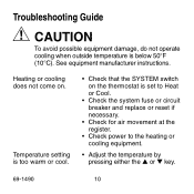
... operate cooling when outside temperature is too warm or cool. • Check that the SYSTEM switch on . Heating or cooling does not come on the thermostat is set to Heat or Cool. • Check the system fuse or circuit breaker and replace or reset if necessary. • Check for air movement...
... operate cooling when outside temperature is too warm or cool. • Check that the SYSTEM switch on . Heating or cooling does not come on the thermostat is set to Heat or Cool. • Check the system fuse or circuit breaker and replace or reset if necessary. • Check for air movement...
Owner's Manual
Page 11
For service, contact your local heating and cooling contractor: 11 69-1490 If you have questions concerning this thermostat, call Honeywell Customer Assistance at 1-800-468-1502, Monday-Friday, 7:00 am-5:30 pm, Central time.
For service, contact your local heating and cooling contractor: 11 69-1490 If you have questions concerning this thermostat, call Honeywell Customer Assistance at 1-800-468-1502, Monday-Friday, 7:00 am-5:30 pm, Central time.
Installation Instructions
Page 1
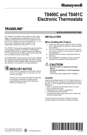
... affected by non-volatile memory for °F or °C. drafts or dead spots behind the thermostat. Registered Trademark Copyright © 2002 Honeywell • • All Rights Reserved 69- 1480- 1 T8400C and T8401C Electronic Thermostats INSTALLATION INSTRUCTIONS The T8400C and T8401C Thermostats provide singlestage, non-programmable temperature control for covering wallmarks. CAUTION Electrical Shock or Equipment Damage...
... affected by non-volatile memory for °F or °C. drafts or dead spots behind the thermostat. Registered Trademark Copyright © 2002 Honeywell • • All Rights Reserved 69- 1480- 1 T8400C and T8401C Electronic Thermostats INSTALLATION INSTRUCTIONS The T8400C and T8401C Thermostats provide singlestage, non-programmable temperature control for covering wallmarks. CAUTION Electrical Shock or Equipment Damage...
Installation Instructions
Page 2
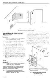
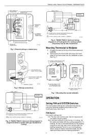
... application. 4. After wiring the wallplate, plug the hole to Wall IMPORTANT Level only for wiring the T8400C and T8401C Thermostats. NOTE: To ensure proper mounting of the terminals. All wiring must comply with local electrical codes and ordinances. The.... 3. x 5-3/4 IN. DECORATOR COVER PLATE WALL 1 2 WALL ANCHORS (2) Wiring IMPORTANT Use an 18-gauge maximum wire for appearance. T8400C AND T8401C ELECTRONIC THERMOSTATS YES NO NO 5 FEET [1.5 METERS] NO M10308 Fig. 1. Mounting Decorator Cover Plate and Wallplate to prevent drafts from the system transformer...
... application. 4. After wiring the wallplate, plug the hole to Wall IMPORTANT Level only for wiring the T8400C and T8401C Thermostats. NOTE: To ensure proper mounting of the terminals. All wiring must comply with local electrical codes and ordinances. The.... 3. x 5-3/4 IN. DECORATOR COVER PLATE WALL 1 2 WALL ANCHORS (2) Wiring IMPORTANT Use an 18-gauge maximum wire for appearance. T8400C AND T8401C ELECTRONIC THERMOSTATS YES NO NO 5 FEET [1.5 METERS] NO M10308 Fig. 1. Mounting Decorator Cover Plate and Wallplate to prevent drafts from the system transformer...
Installation Instructions
Page 3
...with gas heat/electric cooling. In heating, the fan is controlled directly by using an electric heat thermostat, the fan starts and stops with the heating equipment. 3 69-1480-1 W Y T8400C, T8401C W Y G R 2C 1 L1 (HOT) 24V L2 COOLING CONTACTOR 1 L1 (HOT... INSERTION STRIP 5/16 IN. (8 MM) C TERMINAL SCREW Fig. 4. Wiring connections. M11021B Fig. 5. Mounting thermostat wallplate. Use for most systems). T8400C AND T8401C ELECTRONIC THERMOSTATS KEEP WIRING IN SHADED AREA ALTERNATE MOUNTING SCREW HOLE W Y G R C MOUNTING SCREW HOLE ALTERNATE MOUNTING SCREW ...
...with gas heat/electric cooling. In heating, the fan is controlled directly by using an electric heat thermostat, the fan starts and stops with the heating equipment. 3 69-1480-1 W Y T8400C, T8401C W Y G R 2C 1 L1 (HOT) 24V L2 COOLING CONTACTOR 1 L1 (HOT... INSERTION STRIP 5/16 IN. (8 MM) C TERMINAL SCREW Fig. 4. Wiring connections. M11021B Fig. 5. Mounting thermostat wallplate. Use for most systems). T8400C AND T8401C ELECTRONIC THERMOSTATS KEEP WIRING IN SHADED AREA ALTERNATE MOUNTING SCREW HOLE W Y G R C MOUNTING SCREW HOLE ALTERNATE MOUNTING SCREW ...
Installation Instructions
Page 4
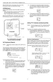
... the setpoint several degrees. FAN SWITCH SYSTEM SWITCH M18417 Fig. 8. To display the temperature setpoint on . M14685 2. Heat: The thermostat controls the heating system. Digital display and system switches (FAN and SYSTEM). Change the SYSTEM switch setting to the °F/°C ... s key momentarily displays 01. When the keys are released, these two-digit codes are shown separately on and off ; T8400C AND T8401C ELECTRONIC THERMOSTATS Slide the FAN switch in °C, set the temperature setpoint to 11°C. M14682 Setting °F/°C Indication and Heat...
... the setpoint several degrees. FAN SWITCH SYSTEM SWITCH M18417 Fig. 8. To display the temperature setpoint on . M14685 2. Heat: The thermostat controls the heating system. Digital display and system switches (FAN and SYSTEM). Change the SYSTEM switch setting to the °F/°C ... s key momentarily displays 01. When the keys are released, these two-digit codes are shown separately on and off ; T8400C AND T8401C ELECTRONIC THERMOSTATS Slide the FAN switch in °C, set the temperature setpoint to 11°C. M14682 Setting °F/°C Indication and Heat...
Installation Instructions
Page 5
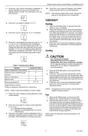
... s key to the desired room temperature. Cooling CAUTION Low Temperature Hazard. M18420 5 69-1480-1 Factory information is displayed. T8400C AND T8401C ELECTRONIC THERMOSTATS 10. To change the setpoint to raise the temperature setting several degrees below the room temperature. Stop scrolling when the desired ...rate is shown, but CC varies by model. M14690 Table 1. M18419A 8. When using an electric heat thermostat, the fan starts and stops with the heating equipment. Press the t key to normal operation. The fan starts and stops with the...
... s key to the desired room temperature. Cooling CAUTION Low Temperature Hazard. M18420 5 69-1480-1 Factory information is displayed. T8400C AND T8401C ELECTRONIC THERMOSTATS 10. To change the setpoint to raise the temperature setting several degrees below the room temperature. Stop scrolling when the desired ...rate is shown, but CC varies by model. M14690 Table 1. M18419A 8. When using an electric heat thermostat, the fan starts and stops with the heating equipment. Press the t key to normal operation. The fan starts and stops with the...


