
Owner's Manual
Page 1
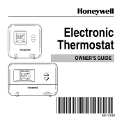
M18539 1 69-1490 69-1490 Set Room FAN Auto On SYSTEM Cool Off Heat M18535 Em Ht Aux Ht Set Room Electronic Thermostat OWNER'S GUIDE FAN Auto On SYSTEM Cool Off Heat Em.Ht.
M18539 1 69-1490 69-1490 Set Room FAN Auto On SYSTEM Cool Off Heat M18535 Em Ht Aux Ht Set Room Electronic Thermostat OWNER'S GUIDE FAN Auto On SYSTEM Cool Off Heat Em.Ht.
Owner's Manual
Page 2
Batteries are not required because your temperature settings are held permanently in an effort to provide you to use. Congratulations on the purchase of this thermostat in memory. 69-1490 2 Over 100 years of Honeywell engineering expertise went into the making of your temperature setting. • Large digital display. The ▲ and ▼ keys make it easy for batteries. You can easily read the current room temperature at a glance. • No need for you with a more comfortable and convenient living environment. • Simple and easy to change your new thermostat!
Batteries are not required because your temperature settings are held permanently in an effort to provide you to use. Congratulations on the purchase of this thermostat in memory. 69-1490 2 Over 100 years of Honeywell engineering expertise went into the making of your temperature setting. • Large digital display. The ▲ and ▼ keys make it easy for batteries. You can easily read the current room temperature at a glance. • No need for you with a more comfortable and convenient living environment. • Simple and easy to change your new thermostat!
Owner's Manual
Page 3
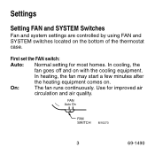
FAN Auto On FAN SWITCH M10273 3 69-1490 In heating, the fan may start a few minutes after the heating equipment comes on with the cooling equipment. On: The fan runs continuously. In cooling, the fan goes off and on . Use for most homes. First set the FAN switch: Auto: Normal setting for improved air circulation and air quality. Settings Setting FAN and SYSTEM Switches Fan and system settings are controlled by using FAN and SYSTEM switches located on the bottom of the thermostat case.
FAN Auto On FAN SWITCH M10273 3 69-1490 In heating, the fan may start a few minutes after the heating equipment comes on with the cooling equipment. On: The fan runs continuously. In cooling, the fan goes off and on . Use for most homes. First set the FAN switch: Auto: Normal setting for improved air circulation and air quality. Settings Setting FAN and SYSTEM Switches Fan and system settings are controlled by using FAN and SYSTEM switches located on the bottom of the thermostat case.
Owner's Manual
Page 4
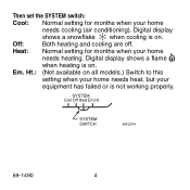
Digital display shows a flame when heating is on all models.) Switch to this setting when your home needs heat, but your equipment has failed or is on. SYSTEM SWITCH M10274 69-1490 4 Ht.: (Not available on . Then set the SYSTEM switch: Cool: Normal setting for months when your home needs cooling (air conditioning). Heat: Normal setting for months when your home needs heating. Em. SYSTEM Cool Off Heat Em.Ht. Digital display shows a snowflake when cooling is not working properly. Off: Both heating and cooling are off.
Digital display shows a flame when heating is on all models.) Switch to this setting when your home needs heat, but your equipment has failed or is on. SYSTEM SWITCH M10274 69-1490 4 Ht.: (Not available on . Then set the SYSTEM switch: Cool: Normal setting for months when your home needs cooling (air conditioning). Heat: Normal setting for months when your home needs heating. Em. SYSTEM Cool Off Heat Em.Ht. Digital display shows a snowflake when cooling is not working properly. Off: Both heating and cooling are off.
Owner's Manual
Page 5
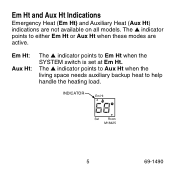
Em Ht: Aux Ht: The ▲ indicator points to help handle the heating load. The ▲ indicator points to Aux Ht when the living space needs auxiliary backup heat to Em Ht when the SYSTEM switch is set at Em Ht. INDICATOR Em Ht Set Room M18425 5 69-1490 Em Ht and Aux Ht Indications Emergency Heat (Em Ht) and Auxiliary Heat (Aux Ht) indications are active. The ▲ indicator points to either Em Ht or Aux Ht when these modes are not available on all models.
Em Ht: Aux Ht: The ▲ indicator points to help handle the heating load. The ▲ indicator points to Aux Ht when the living space needs auxiliary backup heat to Em Ht when the SYSTEM switch is set at Em Ht. INDICATOR Em Ht Set Room M18425 5 69-1490 Em Ht and Aux Ht Indications Emergency Heat (Em Ht) and Auxiliary Heat (Aux Ht) indications are active. The ▲ indicator points to either Em Ht or Aux Ht when these modes are not available on all models.
Owner's Manual
Page 6
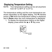
The ▼ indicator points to Set when the temperature setting is displayed and to 37°C). Set Room INDICATOR M18441 69-1490 6 Displaying Temperature Setting NOTE: Your temperature setting can be set anywhere from 40° to 99°F (5° to Room when the room temperature is displayed. 1. To display the temperature setting on the digital display. The temperature setting and the room temperature are shown separately on the digital display, press either the ▲ or ▼ key once.
The ▼ indicator points to Set when the temperature setting is displayed and to 37°C). Set Room INDICATOR M18441 69-1490 6 Displaying Temperature Setting NOTE: Your temperature setting can be set anywhere from 40° to 99°F (5° to Room when the room temperature is displayed. 1. To display the temperature setting on the digital display. The temperature setting and the room temperature are shown separately on the digital display, press either the ▲ or ▼ key once.
Owner's Manual
Page 7
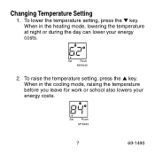
To lower the temperature setting, press the ▼ key. Set Room M18443 7 69-1490 Changing Temperature Setting 1. To raise the temperature setting, press the ▲ key. When in the heating mode, lowering the temperature at night or during the day can lower your energy costs. When in the cooling mode, raising the temperature before you leave for work or school also lowers your energy costs. Set Room M18442 2.
To lower the temperature setting, press the ▼ key. Set Room M18443 7 69-1490 Changing Temperature Setting 1. To raise the temperature setting, press the ▲ key. When in the heating mode, lowering the temperature at night or during the day can lower your energy costs. When in the cooling mode, raising the temperature before you leave for work or school also lowers your energy costs. Set Room M18442 2.
Owner's Manual
Page 8
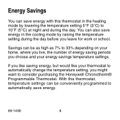
... the cooling mode by lowering the temperature setting 5°F (3°C) to automatically save energy. 69-1490 8 Energy Savings You can also save energy in the heating mode by raising the temperature setting during the day. You can save energy with this thermostat, temperature settings can be conveniently programmed to 10°F (5°C) at night and during the day before you might want to consider purchasing the Honeywell Chronotherm® Programmable Thermostat.
... the cooling mode by lowering the temperature setting 5°F (3°C) to automatically save energy. 69-1490 8 Energy Savings You can also save energy in the heating mode by raising the temperature setting during the day. You can save energy with this thermostat, temperature settings can be conveniently programmed to 10°F (5°C) at night and during the day before you might want to consider purchasing the Honeywell Chronotherm® Programmable Thermostat.
Owner's Manual
Page 9
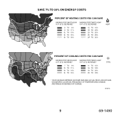
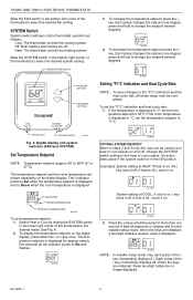
...DAY 10°F (5°C) INCREASE* 7 TO 9% 10 TO 11% 12 TO 14% 14 TO 19% SAVINGS FOR TWICE-A-DAY 10°F (5°C) INCREASE* 11 TO 15% 16 TO 18% 19 TO 22% 23 TO 33% COOL * YOUR SAVINGS DEPENDS ON HOME SIZE AND ACTUAL HEAT LOSS OR GAIN, GEOGRAPHIC LOCATION, FREQUENCY OF TEMPERATURES CHANGE, AND RANGE... IN DEGREES OF CHANGE.
...DAY 10°F (5°C) INCREASE* 7 TO 9% 10 TO 11% 12 TO 14% 14 TO 19% SAVINGS FOR TWICE-A-DAY 10°F (5°C) INCREASE* 11 TO 15% 16 TO 18% 19 TO 22% 23 TO 33% COOL * YOUR SAVINGS DEPENDS ON HOME SIZE AND ACTUAL HEAT LOSS OR GAIN, GEOGRAPHIC LOCATION, FREQUENCY OF TEMPERATURES CHANGE, AND RANGE... IN DEGREES OF CHANGE.
Owner's Manual
Page 10
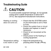
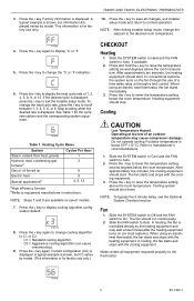
Troubleshooting Guide CAUTION To avoid possible equipment damage, do not operate cooling when outside temperature is set to Heat or Cool. • Check the system fuse or circuit breaker and replace or reset if necessary. • Check for air movement at the register. • Check power to the heating or cooling equipment. • Adjust the temperature by pressing either the ▲ or ▼ key. 69-1490 10...
Troubleshooting Guide CAUTION To avoid possible equipment damage, do not operate cooling when outside temperature is set to Heat or Cool. • Check the system fuse or circuit breaker and replace or reset if necessary. • Check for air movement at the register. • Check power to the heating or cooling equipment. • Adjust the temperature by pressing either the ▲ or ▼ key. 69-1490 10...
Owner's Manual
Page 11
For service, contact your local heating and cooling contractor: 11 69-1490 If you have questions concerning this thermostat, call Honeywell Customer Assistance at 1-800-468-1502, Monday-Friday, 7:00 am-5:30 pm, Central time.
For service, contact your local heating and cooling contractor: 11 69-1490 If you have questions concerning this thermostat, call Honeywell Customer Assistance at 1-800-468-1502, Monday-Friday, 7:00 am-5:30 pm, Central time.
Owner's Manual
Page 12
Automation and Control Solutions Honeywell International Inc. Honeywell Limited-Honeywell Limitée 1985 Douglas Drive North 35 Dynamic Drive Golden Valley, MN 55422 Scarborough, Ontario M1V 4Z9 Copyright © 2000 Honeywell All Rights Reserved ® U.S. Registered Trademark 69-1490 J.H. 9-00 6ww9w-1.h4o9ne0ywell.com/yourhome 12
Automation and Control Solutions Honeywell International Inc. Honeywell Limited-Honeywell Limitée 1985 Douglas Drive North 35 Dynamic Drive Golden Valley, MN 55422 Scarborough, Ontario M1V 4Z9 Copyright © 2000 Honeywell All Rights Reserved ® U.S. Registered Trademark 69-1490 J.H. 9-00 6ww9w-1.h4o9ne0ywell.com/yourhome 12
Installation Instructions
Page 1
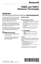
... air from the sun or appliances. - Installer must be set for all models. Location Install the thermostat about 5 ft (1.5m) above the floor in corners. - Handle it can be a trained, experienced service technician. 4. T8400C and T8401C Electronic Thermostats INSTALLATION INSTRUCTIONS The T8400C and T8401C Thermostats provide singlestage, non-programmable temperature control for your application. 3. The T8401C Thermostat is powered through the heating/ cooling system controls. Failure to make sure the product is replacing a control...
... air from the sun or appliances. - Installer must be set for all models. Location Install the thermostat about 5 ft (1.5m) above the floor in corners. - Handle it can be a trained, experienced service technician. 4. T8400C and T8401C Electronic Thermostats INSTALLATION INSTRUCTIONS The T8400C and T8401C Thermostats provide singlestage, non-programmable temperature control for your application. 3. The T8401C Thermostat is powered through the heating/ cooling system controls. Failure to make sure the product is replacing a control...
Installation Instructions
Page 2
.... Typical location of straight or wraparound wiring connections; The thermostat functions normally even when not level. NOTE: Only SUPER TRADELINE® models have the cover plate. Pull the thermostat wire through the entrance hole on the decorator cover plate, then through the heating/ cooling system controls and is adaptable to most 4-wire, 18 to Wall IMPORTANT Level only for wiring the T8400C and T8401C Thermostats. Select the two mounting holes...
.... Typical location of straight or wraparound wiring connections; The thermostat functions normally even when not level. NOTE: Only SUPER TRADELINE® models have the cover plate. Pull the thermostat wire through the entrance hole on the decorator cover plate, then through the heating/ cooling system controls and is adaptable to most 4-wire, 18 to Wall IMPORTANT Level only for wiring the T8400C and T8401C Thermostats. Select the two mounting holes...
Installation Instructions
Page 3
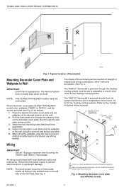
... of the thermostat case. M11021B Fig. 5. OPERATION Setting FAN and SYSTEM Switches Fan and system settings are : On: The fan runs continuously. PROVIDE DISCONNECT MEANS AND OVERLOAD PROTECTION AS REQUIRED. 2 IN T8401C INSTALLATIONS, CONNECT C TERMINAL. T8400C/T8401C heat-cool wiring diagram in single transformer system with gas heat/electric cooling. Set Room Set Room FAN Auto On SYSTEM Cool Off Heat FAN Auto SYSTEM Cool Off Heat A ENGAGE TABS AT TOP OF THERMOSTAT WITH SLOTS ON WALLPLATE. See Fig. 8. DASHED LINES INDICATE TABS ON...
... of the thermostat case. M11021B Fig. 5. OPERATION Setting FAN and SYSTEM Switches Fan and system settings are : On: The fan runs continuously. PROVIDE DISCONNECT MEANS AND OVERLOAD PROTECTION AS REQUIRED. 2 IN T8401C INSTALLATIONS, CONNECT C TERMINAL. T8400C/T8401C heat-cool wiring diagram in single transformer system with gas heat/electric cooling. Set Room Set Room FAN Auto On SYSTEM Cool Off Heat FAN Auto SYSTEM Cool Off Heat A ENGAGE TABS AT TOP OF THERMOSTAT WITH SLOTS ON WALLPLATE. See Fig. 8. DASHED LINES INDICATE TABS ON...
Installation Instructions
Page 4
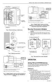
... than one degree; The temperature setpoint is displayed in °F, set the temperature setpoint to select the desired system setting. NOTE: M14686 In installer setup mode only, each press of the t key momentarily displays 02. SYSTEM Switch System switch settings control thermostat operation as the indicator points to test heat or cool outputs. When the keys are off , t turns it off ; T8400C AND T8401C ELECTRONIC THERMOSTATS Slide the FAN switch in the Off position.
... than one degree; The temperature setpoint is displayed in °F, set the temperature setpoint to select the desired system setting. NOTE: M14686 In installer setup mode only, each press of the t key momentarily displays 02. SYSTEM Switch System switch settings control thermostat operation as the indicator points to test heat or cool outputs. When the keys are off , t turns it off ; T8400C AND T8401C ELECTRONIC THERMOSTATS Slide the FAN switch in the Off position.
Installation Instructions
Page 5
... operation. Slide the SYSTEM switch to Cool and the FAN switch to display cooling algorithm configuration default. T8400C AND T8401C ELECTRONIC THERMOSTATS 10. M14687 4. System Steam, radiant floor heat, gravity Hydronic heat, condensing gas furnacea Gas or oil forced air Electric heat Special applicationsb Cycles Per Hour 1 3 6 9 4, 5, 12 aHigh efficiency furnace. Press the s key again. Press the t key to change the °C or °F indication. Cooling system should start . 3. Press the s key to Auto...
... operation. Slide the SYSTEM switch to Cool and the FAN switch to display cooling algorithm configuration default. T8400C AND T8401C ELECTRONIC THERMOSTATS 10. M14687 4. System Steam, radiant floor heat, gravity Hydronic heat, condensing gas furnacea Gas or oil forced air Electric heat Special applicationsb Cycles Per Hour 1 3 6 9 4, 5, 12 aHigh efficiency furnace. Press the s key again. Press the t key to change the °C or °F indication. Cooling system should start . 3. Press the s key to Auto...
Installation Instructions
Page 6
Automation and Control Solutions Honeywell Honeywell Limited-Honeywell Limitée 1985 Douglas Drive North 35 Dynamic Drive Golden Valley, MN 55422 Scarborough, Ontario M1V 4Z9 69-1480-1 G.H. Rev. 2-02 www.honeywell.com/yourhome
Automation and Control Solutions Honeywell Honeywell Limited-Honeywell Limitée 1985 Douglas Drive North 35 Dynamic Drive Golden Valley, MN 55422 Scarborough, Ontario M1V 4Z9 69-1480-1 G.H. Rev. 2-02 www.honeywell.com/yourhome


